

Page 1
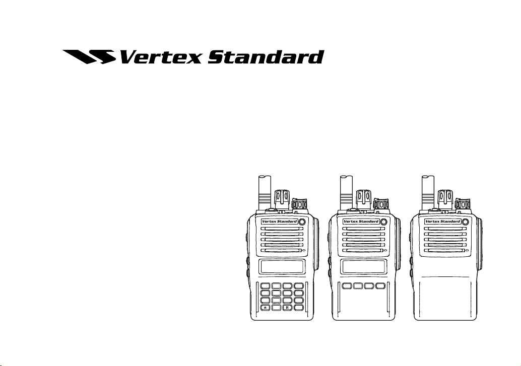
VX-820E S
OPERATING MANUAL
ERIES
Vertex Standard LMR, Inc.
A321
B654
C987
D0
16-Key Version 4-Key Version Non-LCD Version
ABCD
Page 2
CONTENTS
Warning! FCC RF Exposure Requirements ................ 2
Controls & Connectors (16-Key Version) .................... 4
Controls & Connectors (4-Key Version) ...................... 5
Controls & Connectors (Non-LCD Version) ............... 6
LCD Icons & Indicators (16-Key & 4-Key Versions) . 7
Before You Begin ........................................................... 8
Battery Pack Installation and Removal ...................... 8
Low Battery Indication .............................................. 8
Disposal of your Electronic and
Electric Equipment
Products with the symbol (crossed-out wheeled bin)
cannot be disposed as household waste.
Electronic and Electric Equipment should be recycled
at a facility capable of handling these items and their
waste byproducts.
In EU countries, please contact your local
equipment supplier representative or service
center for information about the waste collection system in your country.
Operation........................................................................ 9
Preliminary Steps ....................................................... 9
Operation Quick Start ................................................ 9
Automatic Time-Out Timer...................................... 11
Advanced Operation ................................................... 12
Programmable Key and Toggle Switch Functions ... 12
Descriptipon of Operating Functions ....................... 14
ARTS (Auto Range Transpond System) .................... 22
DTMF Paging System.................................................. 22
User Set Mode (16-Key & 4-Key Versions) ............... 23
Optional Accessories .................................................... 24
Page 3
Congratulations!
You now have at your fingertips a valuable communications tool-a VERTEX STANDARD two-way radio!
Rugged, reliable and easy to use, your VERTEX STANDARD radio will keep you in constant touch with
your colleagues for years to come, with negligible maintenance down-time. Please take a few minutes to
read this manual carefully. The information presented here will allow you to derive maximum performance
from your radio, in case questions arise later on.
We’re glad you joined the VERTEX STANDARD team. Call on us anytime, because communications is
our business. Let us help you get your message across.
Notice!: There are no owner-serviceable parts inside the radio. All service jobs must be referred to an
authorized VERTEX STANDARD Service Representative. Consult your Authorized VERTEX STANDARD
Dealer for installation of optional accessories.
ATTENTION IN CASE OF USE
This transceiver works on frequencies which are not generally permitted.
For frequency allocation, apply for a licence at your local spectrum management authority.
For actual usage contact your dealer or sales shop in order to get your transceiver adjusted to the allocated frequency range.
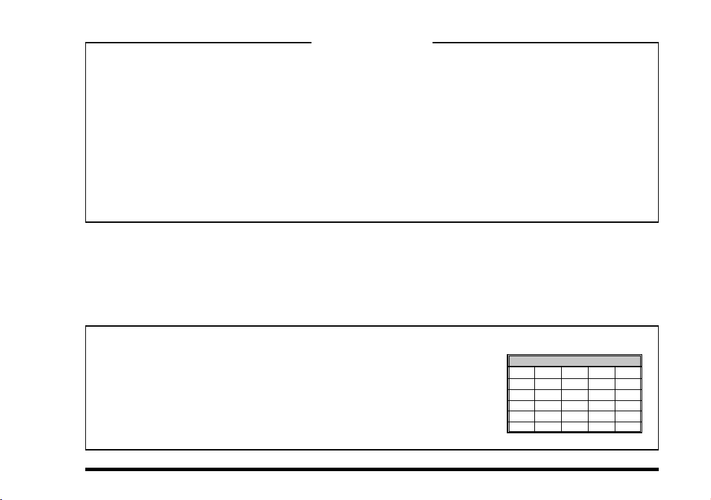
List of the practicable area
AUT BEL CYP CZE DNK
EST FIN FRA DEU GRC
HUN ISL IRL ITA LVL
LIE LTU LUX MLT NLD
NOR POL PRT S VK SVN
ESP SWE CHE GBR ---
VX-820E SERIES OPERATING MANUAL
1
Page 4
WARNING! RF EXPOSURE REQUIREMENTS
This Radio has been tested and complies with the 1999/519/EC RF exposure limits. In addition, it complies
with the following Standards and Guidelines:
ANSI/IEEE C95.1-1992, IEEE Standard for Safety Levels with Respect to Human Exposure to Radio Fre-
quency Electromagnetic Fields, 3 kHz to 300 GHz.
ANSI/IEEE C95.3-1992, IEEE Recommended Practice for the Measurement of Potentially Hazardous Elec-
tromagnetic Fields - RF and Microwave.
WARNING:
This radio generates RF electromagnetic energy during transmit mode. This radio is designed for and
classified as Occupational Use Only, meaning it must be used only during the course of employment by
individuals aware of the hazards, and the ways to minimize such hazards. This radio is not intended for
use by the General Population in an uncontrolled environment.
This radio is NOT approved for use by the general population in an uncontrolled exposure environ-
ment. This radio is restricted to occupational use, work related operations only where the radio operator must have the knowledge to control his or her RF exposure conditions.
When transmitting, hold the radio in a vertical position with its microphone 2 inches (5 cm) away
from your mouth and keep the antenna at least 2 inches (5 cm) away from your head and body.
The radio must be used with a maximum operating duty cycle not exceeding 50%, in typical Push-to-
Talk configurations.
DO NOT transmit for more than 50% of total radio use time (50% duty cycle). Transmitting more
than 50% of the time can cause RF exposure compliance requirements to be exceeded.
The radio is transmitting when the red LED on the top of the radio is illuminated. You can cause the
radio to transmit by pressing the P-T-T button.
SAR compliance for body-worn use was only demonstrated for the specific belt-clip Part Number
(#RA060190A). Other body-worn accessories or configurations may NOT comply with the RF expo-
2
VX-820E SERIES OPERATING MANUAL
Page 5

WARNING! RF EXPOSURE REQUIREMENTS
sure requirements and should be avoided.
DO NOT transmit when the radio is used in Body Worn configuration with the following accessory:
belt-clip.
It must be used ONLY for (1) there is 4 cm distance from the body during transmitting, (2) monitoring purposes, using the speaker only and (3) for carrying purposes.
Always use Vertex Standard authorized accessories.
The information listed above provides the user with the information needed to make him or her
aware of RF exposure, and what to do to assure that this radio operates with the RF exposure limits of
this radio.
Electromagnetic Interference/Compatibility
During transmissions, this radio generates RF energy that can possibly cause interference with
other devices or systems. To avoid such interference, turn off the radio in areas where signs are
posted to do so.
Do not operate the transmitter in areas that are sensitive to electromagnetic radiation such as hospitals, health care facilities, aircraft, and blasting sites.
VX-820E SERIES OPERATING MANUAL
3
Page 6
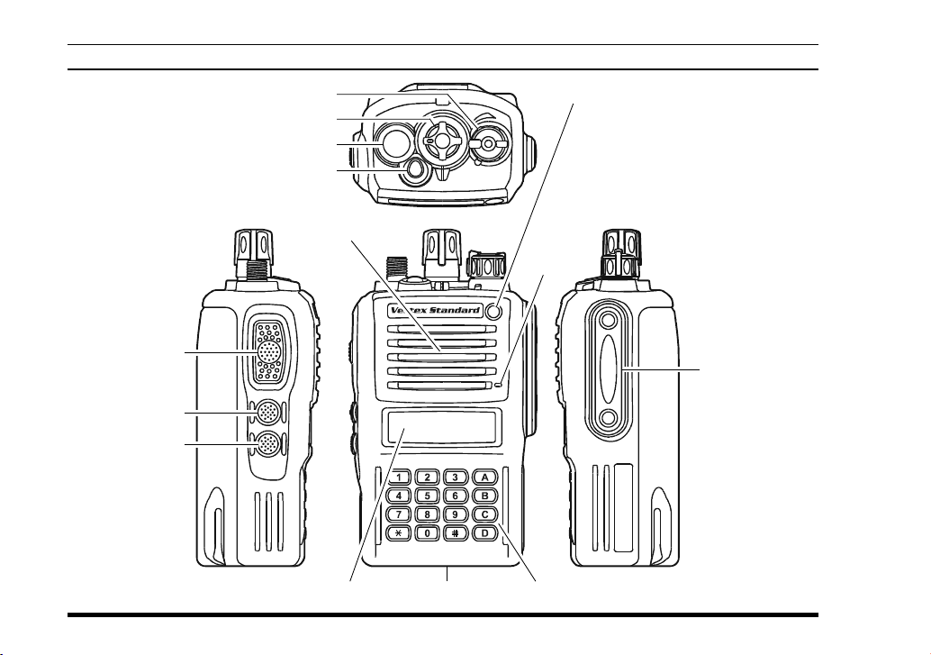
CONTROLS & CONNECTORS (16-KEY VERSION
)
PTT Switch
MONITOR Button
LAMP Button
4
VOL/PWR Knob
CH (Channel) Selector
Antenna Jack
TOP SEL Key
Speaker
LED Indicator
Steady Red:
Transmitting in progress
Blinking Green:
Busy Channel
Steady Green:
Tone Squelch in defeated condition
Dealer Programmed Color
Emergency, 5-Tone Decoded, or
2-Tone Decoded
: one of “Flashing in white,”
“Continuation changes in
Microphone
)
Battery Pack LatchLCD (Liquid Crystal Display
16-Button DTMF Keypad
sequential colors,” or “toggling the two colors.”
:
MIC/SP Jack
(
External MIC/SP
)
VX-820E SERIES OPERATING MANUAL
Page 7
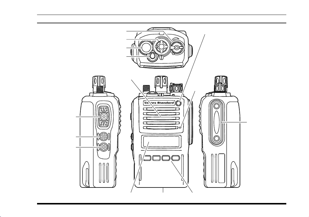
CONTROLS & CONNECTORS (4-KEY VERSION
)
VOL/PWR Knob
CH (Channel) Selector
Antenna Jack
TOP SEL Key
Speaker
PTT Switch
MONITOR Button
LAMP Button
VX-820E SERIES OPERATING MANUAL
ABCD
)
Battery Pack LatchLCD (Liquid Crystal Display
LED Indicator
Steady Red:
Transmitting in progress
Blinking Green:
Busy Channel
Steady Green:
Tone Squelch in defeated condition
Dealer Programmed Color
Emergency, 5-Tone Decoded, or
2-Tone Decoded
: one of “Flashing in white,”
“Continuation changes in
Microphone
4-Button Programmable Key
sequential colors,” or “toggling the two colors.”
:
MIC/SP Jack
(
External MIC/SP
)
5
Page 8
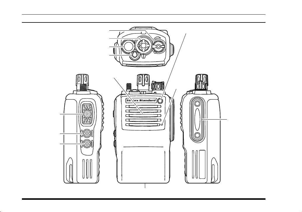
CONTROLS & CONNECTORS (NON-LCD VERSION
)
PTT Switch
MONITOR Button
LAMP Button
6
VOL/PWR Knob
CH (Channel) Selector
Antenna Jack
TOP SEL Key
Speaker
Battery Pack Latch
LED Indicator
Steady Red:
Transmitting in progress
Blinking Green:
Busy Channel
Steady Green:
Microphone
Tone Squelch in defeated condition
Dealer Programmed Color
Emergency, 5-Tone Decoded, or
2-Tone Decoded
: one of “Flashing in white,”
“Continuation changes in
sequential colors,” or “toggling the two colors.”
:
MIC/SP Jack
(
External MIC/SP
VX-820E SERIES OPERATING MANUAL
)
Page 9
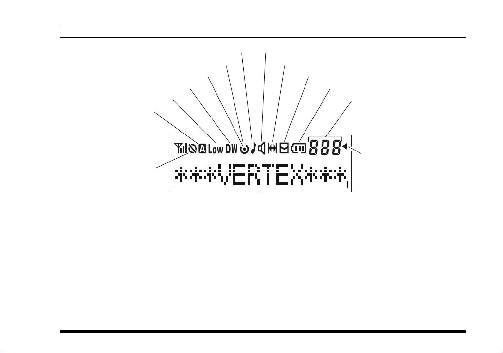
LCD ICONS & INDICATORS (16-KEY & 4-KEY VERSIONS
This channel on “SCAN” List
Priority Scan is activated
“DUAL WATCH” is activated
Low Transmit Power Mode On
Option SW (Key Func-
tion) is activated
RSSI Indicator (four steps)
Encryption is activated
)
“CALL” Indicator Receiver Monitor
“Talk-Around” is enabled
“Voice Message” is received
Battery Indicator
SUB-LCD
888: Channel Group Number
-P-: Priority Channel
-H-: Home Channel
In: ARTS “In Range”
Out: ARTS “Out of Range”
“Group Scan” is enabled
12 Character Alpha-numeric Display
VX-820E SERIES OPERATING MANUAL
7
Page 10
BEFORE YOU BEGIN
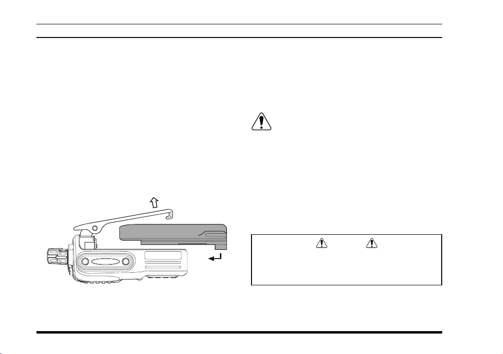
Battery Pack Installation and Removal
To install the battery, hold the transceiver with
your left hand, so your palm is over the speaker
and your thumb is on the top of the belt clip. Carefully mate the battery’s four insertion slots with
their corresponding alignment tabs on the transceiver case, while tilting the Belt Clip outward.
Proper alignment occurs with the battery pack
offset about 1/2 inch from the top edge of the battery compartment.
Guide the pack on to the tabs with a slight inward
pressure, then slide the battery pack upward, until it locks in place with a “Click.”
Tilt the Belt Clip
Insert the Battery Pack
To remove the battery, turn the radio off and re-
move any protective cases. Slide the Battery Pack
Latch on the bottom of the radio toward the front
panel while sliding the battery down about 1/2
inch. Then lift the battery out from the radio while
unfolding the Belt Clip.
Do not attempt to open any of the rechargeable Lithium-Ion packs, as they could ex-
plode if accidentally short-circuited.
Low Battery Indication
As the battery discharges during use, the voltage
gradually becomes lower. When the battery voltage
becomes to low, substitute a freshly charged battery
and recharge the depleted pack. The LED indicator
on the top of the radio will blink red when the battery voltage is low.
Caution
Danger of explosion if battery is replaced with
an incorrect battery. Replace only with the same
or equivalent type.
8
VX-820E SERIES OPERATING MANUAL
Page 11
Preliminary Steps
Install a charged battery
pack onto the transceiver, as
described previously.
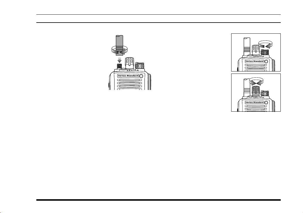
Screw the supplied antenna
onto the Antenna jack.
Never attempt to operate this
transceiver without an antenna connected.
If you have a Speaker/Mi-
crophone, we recommend that it not be connected
until you are familiar with the basic operation of
the VX-820E.
VX-820E SERIES OPERATING MANUAL
OPERATION
Operation Quick Start
Turn the top panel’s
VOL/PWR knob clockwise to turn the radio on.
Turn the top panel’s CH
selector knob to choose
the desired operating
channel. On the 16-key
and 4-key versions, a
channel name will appear
on the LCD.
If you want to select the operating channel from
a different Memory Channel Group, press the Programmable key (assigned to the Memory Group
Up or Down function) to select the Memory Channel Group you want before selecting the operating channel. A Group name will appear on the
LCD whenever the Programmable key is pressed.
Note: Some models are programmed so that the
operating channels are selected by the Programmable key and the memory channel group is selected by the CH selector knob. For further details, contact your VERTEX STANDARD dealer.
9
Page 12
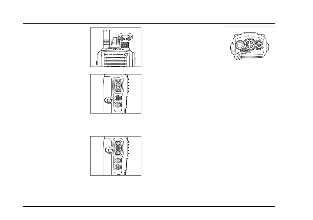
Rotate the VOL/PWR
knob to set the volume
level. If no signal is
present, press and hold in
the MONITOR button
(under the PTT switch)
more than 2 seconds;
background noise will
now be heard, and you
may use this to set the
VOL/PWR knob for the
desired audio level. Press
and hold the MONITOR
button more than 2 seconds (or press the MONI-
TOR button twice) to quiet the noise and resume
normal (quiet) monitoring.
To transmit, monitor the
channel and make sure it
is clear.
Press and hold the PTT
switch. Speak into the microphone area of the front
panel grille (above the upper left edge of the LCD)
in a normal voice level. To return to the Receive
mode, release the PTT switch.
OPERATION
Press the (Orange) TOP
SEL key to activate one
of the preprogrammed
functions which may
have been enabled at the
time of programming by
the dealer. See the next section for details regarding the available features.
If a Speaker/Microphone is available, remove the
plastic cap and its two mounting screws from the
right side of the transceiver, then align the connector of the Speaker/Microphone on the transceiver body; secure the connector pin using the
screws supplied with the Speaker/Microphone.
Hold the speaker grille up next to your ear while
receiving. To transmit, press the PTT switch on
the Speaker/Microphone, just as you would on
the main transceiver’s body, and speak into the
microphone on a normal voice level.
Note 1): Save the original plastic cap and its
mounting screws. They should be reinstalled
when not using the Speaker/Microphone.
2) When you press the PTT switch on the
Speaker/Microphone, it disables the internal microphone, and vice versa.
10
VX-820E SERIES OPERATING MANUAL
Page 13

OPERATION
If the Busy Channel Lockout feature has been
programmed on a channel, the radio will not transmit when a carrier is present. Instead, the radio
will generate short beep three times and indicate
“
ERROR
*
versions). Release the PTT switch and wait for
the channel to be clear of activity.
If CTCSS or Digital Coded Squelch (DCS) Lock-
out has been programmed on a channel, the radio
can transmit only when there is no carrier being
received or when the carrier being received includes the correct CTCSS tone or DCS code.
” on the display (16-key and 4-key
*
Automatic Time-Out Timer
If the selected channel has been programmed for
automatic time-out, you must limit the length of each
transmission. While transmitting, a beep will sound
10 seconds before time-out. Another beep will sound
just before the deadline; the “TX” indicator will disappear and transmission will cease soon thereafter.
To resume transmitting, you must release the PTT
switch and wait for the “penalty timer” to expire.
VX-820E SERIES OPERATING MANUAL
11
Page 14

ADVANCED OPERATION
Programmable Key Functions
All versions of the VX-820E include the TOP SEL,
SIDE SEL, MONITOR, and LAMP keys, and the
TOGGLE switch. The
include the [A], [B], [C]
thermore, the
[#]
function keys. The Programmable key functions
16-key version includes the [
can be customized, via programming by your VERTEX STANDARD dealer, to meet your communications/network requirements. Some features may require the purchase and installation of optional internal accessories. The possible Programmable key programming features are illustrated at the right, and
their functions are explained on page 14. For further
details, contact your VERTEX STANDARD dealer.
16-key and 4-key versions
, and [D] function keys. Fur-
]
and
For future reference, check the box next to each function that has been assigned to the Programmable key
on your particular radio, and keep it handy.
FUNCTION
None
Monitor
Lamp
Scan
Dual Watch
Low Power
Talk Around
TX Save Disable
Encryption
Follow-Me Scan
: Requires FVP-25 or FVP-35 Encryption Unit
TOP SEL
12
MONITOR LAMP
PROGRAMMABLE KEY
[A] [B] [C] [D]
VX-820E SERIES OPERATING MANUAL
[] [#]
Page 15

FUNCTION
Follow-Me Dual Watch
Group Up
Group Down
Channel Up
Channel Down
Set
Call/Reset
Call 1
Call 2
Call 3
Call 4
Call 5
Code Up
Code Down
Code Set
Speed Dial
Option SW 1
Option SW 2
Emergency
Home
Selectable Tone
Direct Channel #1
Direct Channel #2
Direct Channel #3
Direct Channel #4
REC/PLAY
SQL
AF Min Volume
Status Set
Status Up
Status Down
Status Check
Audio PC (PIT)
Lone Worker
DTMF Code Set
TA Scan
: Requires DVS-5 Voice Storage Unit
TOP SEL MONITOR LAMP
VX-820E SERIES OPERATING MANUAL
ADVANCED OPERATION
PROGRAMMABLE KEY
[A]
[B] [C] [D]
/
[] [#]
13
Page 16

ADVANCED OPERATION
Description of Operating Functions
M
ONITOR
Press the assigned programmable key to cancel
CTCSS- and DCS-controlled squelch; the BUSY/
TX indicator will glow green. Press and hold this
button for 1.5 seconds to hear background noise
(unmute the audio); the BUSY/TX indicator will
blink green.
LAMP
Press the assigned programmable key to illuminate
the LCD for five seconds.
SCAN
The Scanning feature is used to monitor multiple signals programmed into the transceiver. While scanning, the transceiver will check each channel for the
presence of a signal, and will stop on a channel if a
signal is present.
To activate scanning:
Press the assigned programmable key to activate
scanning.
The scanner will search the channels of each chan-
nel, looking for active ones; it will pause each time
it finds a channel on which someone is speaking.
Press the assigned programmable key again to dis-
able scanning. Operation will revert to the programmed revert channel.
Note: Your dealer may have programmed your radio to stay on one of the following channels if you
press the PTT switch during scanning pause:
Current channel (“Talk Back”)
“Last Busy” channel
“Priority” channel
“Home” channel
“Scan Start” channel
14
VX-820E SERIES OPERATING MANUAL
Page 17
ADVANCED OPERATION
DUAL WATCH
The Dual Watch feature is similar to the SCAN feature, except that only two channels are monitored:
The current operating channel; and
The Priority channel.
To activate Dual Watch:
Press the assigned programmable key.
The scanner will search the two channels; it will
pause each time it finds a channel on which someone is speaking.
To stop Dual Watch:
Press the assigned programmable key.
Operation will revert to the “Dual Watch Start”
channel.
LOW POWER
Press the assigned programmable key to set the
radio’s transmitter to the “Low Power” mode, thus
extending battery life. Press the key again to return
to “Normal” transmit power when in difficult terrain.
When the radio’s transmitter is set to “Low Power”
mode, the “ ” icon will be indicated on the display.
TALK AROUND (TA
Press the assigned programmable key to activate the
Talk Around feature when you are operating on duplex channel systems (separate receive and transmit
frequencies, utilizing a “repeater” station). The Talk
Around feature allows you to bypass the repeater station and talk directly to a station that is nearby. This
feature has no effect when you are operating on “simplex” channels, where the receive and transmit frequencies are already the same.
When the “TA” function is activated, the “
will be indicated on the display.
Note that your dealer may have mode provision for
“Talk Around” channels by programming “repeater”
and “Talk Around” frequencies on two adjacent channels. If so, the key may be used for one of the other
Pre-Programmed Functions.
)
” icon
VX-820E SERIES OPERATING MANUAL
15
Page 18

ADVANCED OPERATION
TX SAVE DISABLE
Press the assigned programmable key to disable the
Transmit Battery Saver, if you are operating in a location where high power is almost always needed.
The Transmit Battery Saver helps extend battery life
by reducing transmit power when a very strong signal from an apparently nearby station is being received. Under some circumstances, though, your
hand-held radio may not be heard well at the other
end of the communication path, and high power may
be necessary at all times.
ENCRYPTION (OPTION)
Press the assigned programmable key to toggle the
Encryption feature “On” and “Off.”
AUDIO PC (PIT
Press the assigned programmable key to toggle the
Audio Pitch Controller “On” and “Off.”
When you turn the Audio Pitch Controller ON, the
receive audio is enhanced in the high-range frequencies.
)
FOLLOW-ME SCAN
The “Follow-Me” Scan feature checks a User-assigned Priority Channel regularly as you scan other
channels. Thus, if only Channels 1, 3, and 5 (of the 8
available channels) are designated for “Scanning,”
the user may nonetheless assign Channel 2 as the
“User-assigned” Priority Channel via the “FollowMe” feature.
To activate “Follow-Me” scanning, first select the
channel you want to designate as the “User-Assigned
Priority Channel” and press the assigned programmable key. Then rotate the CH Selector knob to recall to the “Scanning Start” channel which has been
programmed by your dealer to activate the scanner.
When the scanner stops on an “Active” channel, the
User-assigned Priority Channel will automatically be
checked every few seconds; if activity is found on
the User-assigned Priority Channel, the radio will
switch between it and the Dealer-Assigned Priority
Channel, if any.
16
VX-820E SERIES OPERATING MANUAL
Page 19

ADVANCED OPERATION
FOLLOW-ME DUAL WATCH
To set up a “Dual Watch” frequency pair using the
“Follow-Me” feature, select a channel using the CH
Selector knob. Now press the assigned programmable
key; pressing the assigned programmable key locks
the current channel as the User-assigned Priority
Channel. Now rotate the CH Selector knob to select
another channel (not the “Scanning Start” channel).
Your radio will now switch back-and-forth between
the currently-selected channel and the User-assigned
Priority Channel.
During “Follow-Me” scanning (after you have
pressed the key), you can set up the “Dual Watch”
feature by rotating the CH Selector knob to another
channel. The radio will then scan back and forth between the original User-assigned Priority Channel
and the newly-selected channel.
The Priority Channel you have assigned (before
pressing the key) will be retained in memory until
you change it.
VX-820E SERIES OPERATING MANUAL
GROUP UP/DOWN
Press the assigned programmable key to select a different group of channels. Once the desired Group is
reached, rotate the CH Selector knob to select the
desired channel within the selected Group.
You may wish to have the Scanner pass through more
than one Group during the scanning process (normally, scanning is performed within the current group
only). To include the current Group in the scanning
loop, press and hold in the assigned programmable
key for one second. To remove a Group from Group
Scan, press and hold in the assigned programmable
key again for one second.
Multi-Group Scanning is only possible if you are using the “User Scan” list. To edit the User Scan list,
press and hold the assigned programmable key for
one second to delete the current Memory Group from
the Scanning. Alternatively, press and hold the assigned programmable key for one second to delete
the Current Memory channel from the Scanning.
-
When you delete a Group or channel, “
will appear on the LCD for one second after pressing
the assigned programmable key. To restore a particular channel to your scanning list, press and hold in the
assigned programmable key again for one second;
SCAN Skip
-
”
17
Page 20

ADVANCED OPERATION
-
“
SCAN Stop
ond after pressing the assigned programmable key.
CHANNEL UP/DOWN
Press the assigned programmable key to select a different channel within the current group.
SET
Press the assigned programmable key to activate the
“User Set” (Menu) Mode. See page 20 for details
CALL/RESET
While the DTMF Paging System
This feature, if enabled, allows the user to change
the 3-digit Page Call code, used to call other similarly-equipped stations. Press the assigned programmable key, followed by the three digits representing
the Page Call code of the station you wish to call.
Three tones will be heard after the last key is pressed
(the new code will now be transmitted).
The receiver squelch of the other station will be
opened, and you can begin communication.
While the 2-Tone/5-Tone Paging System
This feature, if enabled, press the assigned programmable key to send a 2-tone/5-tone sequential tone.
-
” will appear on the LCD for one sec-
18
CALL 1 TO CALL 5
Press the assigned programmable key to send a 2tone/5-tone sequential tone group which is pre-defined.
CODE UP/DOWN
Press the assigned programmable key to select a 2tone/5-tone encode code from the pre-defined encode
list.
CODE SET
Press the assigned programmable key to change the
encode digits for 5-tone operation. To change a specific digit, select the desired digit using the [A] key,
then change the number using the [B]/[C] keys, and
store the number using the [D] key.
SPEED DIAL
Your Dealer may have pre-programmed Auto-Dial
telephone number memories into your radio.
To dial a number, press the assigned programmable
key, then press the front panel’s numeric key corresponding to the Auto-Dial memory number list provided by your Dealer or Network Administrator. The
DTMF tones sent during the dialing sequence will
be heard in the speaker.
(
16-KEY VERSION ONLY
VX-820E SERIES OPERATING MANUAL
)
Page 21

ADVANCED OPERATION
OPTION SW1
Press the assigned programmable key to toggle the
optional accessory “1” “On” and “Off.”
OPTION SW2
Press the assigned programmable key to toggle the
optional accessory “2” “On” and “Off.”
EMERGENCY
The VX-820 series include an “Emergency” feature
which may be useful for alerting another party monitoring on the same frequency as your transceiver’s
channel.
Press the assigned programmable key to initiate an
emergency call. For further details contact your
Dealer.
HOME CHANNEL
Press the assigned programmable key to recall the
pre-defined Home group/channel. When you recall
the Home group/channel, the “
pear on the LCD.
H” notation will ap-
SELECTABLE TONE
Press the assigned programmable key to select a subaudible tone (CTCSS/DCS) from the pre-defined
tone table. You can operate using the indicated subaudible tone in the Selectable Tone mode.
DIRECT CH#1 TO #4
Press the assigned programmable key to recall the
Dealer pre-programmed channel directly.
REC/PLAY (VOICE STORAGE: OPTION
This function allows your radio to record a received
voice message, and to play back the recorded audio.
It requires installation of the optional Voice Recording Unit.
Recording;
Press the assigned programmable key for 1.5 seconds to enable the Voice Recording Mode. If the incoming signal is received, so as to un-mute the
squelch and pass audio, then the “
and received audio will be recorded. When the voice
recording is completed, the “
Playback;
Press the assigned programmable key momentarily
to play back the last message.
” Icon will flash
” stays on.
)
VX-820E SERIES OPERATING MANUAL
19
Page 22

ADVANCED OPERATION
To stop the play-back, press the TOP SEL key.
While playback is proceeding, you may press the [A
]
[
key (4-key version) or
jump to the previous message, or press the [B] key
(4-key version) or [#] key (16-key version) to jump
to the next message. Furthermore, press the [D] key
to clear the all messages and stop the play-back.
SQL
You can manually adjust the squelch level using this
function:
Press the assigned programmable key. A tone will
sound, and the current squelch level will appear
on the display.
Press the MONITOR/LAMP button to select the
desired squelch level.
Two seconds after releasing the MONITOR/LAMP
button, the display will revert to the normal channel indication.
AF MIN VR
Press the assigned programmable key to reduce the
audio output to the (lower) level programmed by your
Dealer.
key (16-key version) to
STATUS SET
]
Press the assigned programmable key to change the
5-Tone status code. To change the status code, select
the desired digit by [A] key, then change the number
by [B]/[C] key, and store the number by [D] key.
STATUS UP/DOWN
Press the assigned programmable key to select a 5Tone status code from the pre-defined status list.
STATUS CHECK
Press the assigned programmable key to check the
5-Tone receive status code. When you press this key,
the LCD display will indicate the “Message” corresponding to the receive status condition per the predefined status list.
LONE WORKER
Press the assigned programmable key to toggle the
Lone Worker feature “On” and “Off.”
The Lone Worker feature is designed to emit an alarm
for 30 seconds when the Lone Worker Timer (programmed by your Dealer) has expired. If the user
does not reset the timer by pressing the PTT switch,
the radio switches to the Emergency mode.
20
VX-820E SERIES OPERATING MANUAL
Page 23
ADVANCED OPERATION
DTMF CODE SET
You may send the desired telephone number manually.
To dial a number manually, press the assigned programmable key, then press the desired numbers on
the front panel’s numeric key. Now, press the PTT
switch to send the telephone number. The DTMF
tones sent during the dialing sequence will be heard
in the speaker.
(
16-KEY VERSION ONLY
)
TA S CAN
Press the assigned programmable key to toggle the
TA (Talk Around) scan feature “On” and “Off.”
While TA scan is proceeding, the VX-820E will
search both the transmit and receive frequencies (the
“
” icon will blink). When a signal is encountered
on the receive frequency, the VX-820E will pause
until the signal disappears (“
not blink). When a signal is encountered on the transmit frequency, the VX-820E will check for activity
on the receive frequency every few seconds (interval programmed by your Dealer).
” icon will appear but
VX-820E SERIES OPERATING MANUAL
21
Page 24

ARTS
(
AUTO RANGE TRANSPOND SYSTEM
)
DTMF PAGING SYSTEM
This system is designed to inform you when you and
another ARTS-equipped station are within communication range.
During ARTS operation, when the radio receives the
correct ARTS signal, a short beep will sound and the
“In” (meaning “In Service” notation will be displayed
on the sub-LCD. If you move out of range for more
than two minutes, your radio senses that no signal
has been received; three short beeps will sound, and
“Out” (“Out of Service”) will be displayed on the
sub-LCD. If you subsequently move back into range,
as soon as the other station transmits, a short beep
will sound and “In” will be displayed again on the
sub-LCD.
This system allows paging and selective calling, using DTMF tone sequences.
When your radio is paged by a station bearing a tone
sequence which matches yours, your radio’s squelch
will open and the alert will sound. The three-digit
code of the station which paged you will be displayed
on your radio’s LCD.
LOCK
In order to prevent accidental channel change or inadvertent transmission, various aspects of the
VX-820E’s knob, soft keys, and PTT switch may be
locked.
The precise lockout configulation is programmed by
your Dealer.
To locked out the key locking, turn the radio off. Now,
press and hold the PTT and LAMP key while turning the radio on again.
To cancel locking, repeat this process.
22
VX-820E SERIES OPERATING MANUAL
Page 25
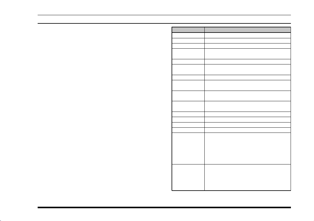
USER SET MODE
The VX-820E Series includes a “User Set (Menu)”
Mode which allows the user to define or configure
various settings, such as Beep On/Off, Squelch, LCD
contrast, etc. To activate the “User Set (Menu)”
Mode:
Press the assigned programmable key for the
“SET” function to enter the “User Set Mode.”
Select the User Set Mode Item you want change
using the CH selector knob.
Press the MONITOR/LAMP button to select the
status of the selected item.
Press PTT switch to exit to normal operation.
VX-820E SERIES OPERATING MANUAL
(
16-KEY & 4-KEY VERSIONS
)
DISPLAY DESCRIPTION
1
SQL
2
SCN List
3
BEEP
4
BELL
5
Lighting
6
Lock
7
Group
8
SCAN
9
DW
10
TA
11
AF MinVR
12
Beep VR
13
Contrast
14
Pitch
15
REC Mode
16
Play Mode
Note: The menu “15: REC Mode” and “16: Play Mode” will ap-
pear only when the Voice Recording Unit is installed.
Select the Squelch Threshold Level
Select the Scan List “User” or “Dealer”
Set the Beep On/Off
Set the Bell On/Off
(Bell engaged by sub-audible CTCSS/DCS)
Set the BUSY/TX LED On/Off
Set the Lock function to be Locked
(Key/PTT/Key+PTT)
Set the Operation Group
Set the Scan status
(same function as Scan key)
Set the Dual Watch status
(same function as DW key)
Set the Talk Around status
(same function as TA key)
Set the Minimum Volume level
Set the Beep volume level
Set the LCD contrast
Not available at this time
ONE: Enables recording one message (max.
120 seconds), and playback from the
beginning of the message.
ROL: Enables recording whenever squelch
opens, and playback of the last 120
seconds.
Set the priority audio on playback mode.
PLY: Playback audio is higher priority than re-
ceived signal
SIG: Received signal is higher priority than
playback audio
23
Page 26

OPTIONAL ACCESSORIES
FNB-V86LIA 7.4V, 1380 mAh Lithium-Ion Battery
FNB-V87LIA 7.4V, 2300 mAh Lithium-Ion Battery
FNB-V92LI 7.4V, 3000 mAh Lithium-Ion Battery
FBA-34 Alkaline Battery Case (6 x AA)
VAC-920 Rapid Charger (CD-31 + PA-42)
CD-31 Desktop Rapid Charger
PA-42 AC Adapter (for CD-31)
VCM-2 Vehiclular Charger Mounting Adapter
(for CD-31)
VT60F VX-Trunk Unit
VT60FS VX-Trunk/Encryption Unit
FVP-25 Encryption/DTMF Pager Unit
FVP-35 Encryption Unit
(Rolling Code Voice Scrambler)
FVP-36 Encryption Unit
DVS-5 Voice Storage Unit
MDC1200 Digital ANI Encoder Unit
®
VME-100 MDC1200
VMDE-200 MDC1200
A7A Submersible Speaker/Microphone
MH-66
B7A Submersible Speaker/Microphone
MH-66
, GE-Star® Encoder Unit
®
, GE-Star® Enc/Dec Unit
(with Speaker-Volume Toggle Switch
& Programmable Key)
Availability of accessories may vary; some accessories are supplied standard per local requirements, others
may be unavailable in some regions.
Check with your VERTEX STANDARD Dealer for changes to this list.
24
ATV-8A VHF Antenna (134-151 MHz)
ATV-8B VHF Antenna (150-163 MHz)
ATV-8C VHF Antenna (161-174 MHz)
ATV-6XL VHF Antenna
(134-174 MHz, Untuned)
ATU-6A1 UHF Antenna (380-450 MHz)
ATU-6C UHF Antenna (440-470 MHz)
ATU-6D UHF Antenna (450-485 MHz)
ATU-6F UHF Antenna (485-520 MHz)
LLC-820 Leather Case
CE59 Programming Software
FIF-8 Flash ROM Writer
FIF-12 USB Programming Interface
CT-29 Serial Programming Interface
CT-108 PC Programming Cable
(for FIF-12)
CT-109 PC Programming kit
(CT-29 + CT-115)
CT-110 PC Programming Cable (for FIF-8)
CT-115 PC Programming Cable (for CT-29)
CT-116 Radio to Radio Cloning Cable
VX-820E SERIES OPERATING MANUAL
Page 27
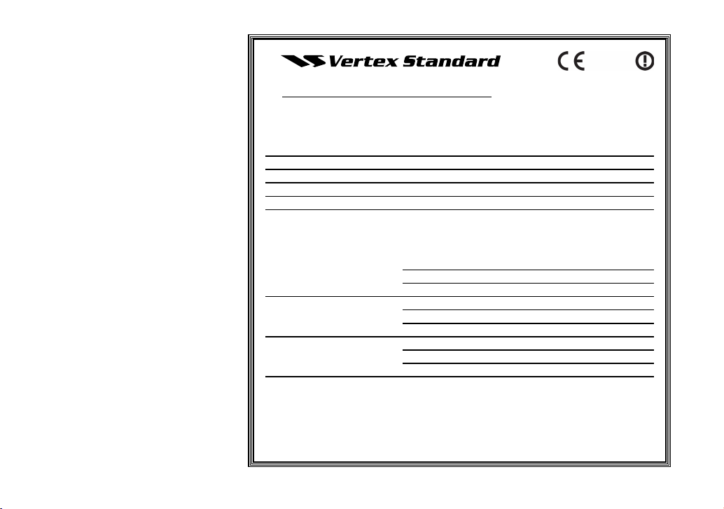
Declaration of Conformity
We, Yaesu UK Ltd. declare under our sole responsibility that the following equipment complies with the essential requirements of the Directive 1999/5/EC.
Type of Equipment: FM Transceiver
Brand Name: VERTEX STANDARD
Model Number: VX-820E/870E Series
Manufacturer: Vertex Standard Co., Ltd.
Address of Manufacturer: 4-8-8 Nakameguro Meguro-Ku, Tokyo 153-8644, Japan
Applicable Standards:
This equipment is tested and conforms to the essential requirements of directive, as
included in following standards.
Radio Standard: EN 300 113-2
EN 300 086-2
EMC Standard: EN 301 489-5
Safety Standard:
The technical documentation as required by the Conformity Assessment procedures is
kept at the following address:
Company: Yaesu UK Ltd.
Address: Unit 12, Sun Valley Business Park, Winnall Close,
Winchester, Hampshire, SO23 0LB, U.K.
EN 301 489-1
EN 60065
Page 28

Copyright 2013
Vertex Standard LMR, Inc.
All rights reserved.
No portion of this manual
may be reproduced
without the permission of
Vertex Standard LMR, Inc.
Printed in China
EC058N276
 Loading...