

Page 1
APCO P25/FM TrAnsCeiver
VX-7200
OPerATing MAnuAl
P1
P2
A
Vertex Standard LMR, Inc.
4-6-8 Shibaura, Minato-ku, Tokyo 108-0023, Japan
P3
P4
Page 2

Congratulations!
You now have at your ngertips a valuable communications tool: a Vertex Standard
two-way radio! Rugged, reliable and easy to use, your Vertex Standard radio will
keep you in constant touch with your colleagues for years to come, with negligible
maintenance downtime.
Please take a few minutes to read this manual carefully. The information presented
here will allow you to derive maximum performance from your radio, in case questions arise later on.
We’re glad you joined the Vertex Standard team. Call on us anytime, because communications is our business. Let us help you get your message across.
Notice !
There are no owner-serviceable parts inside the transceiver. All service jobs
must be referred to an authorized Vertex Standard Service Representative.
Consult your Authorized Vertex Standard Dealer for installation of optional
accessories.
Page 3
inTrOduCTiOn
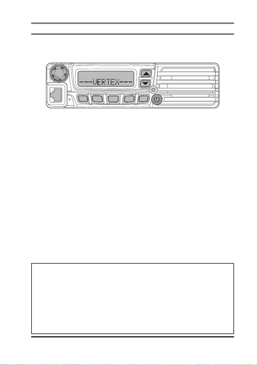
The
VX-7200
P1
P2
A
Series are full-featured APCO P25/FM transceiver designed for
P3
P4
flexible mobile and base station business communications in the VHF or UHF
Land Mobile bands. These transceiver are designed for reliable business communications in a wide variety of applications with a wide range of operating capability
provided by their leading-edge design.
The 501-channel memories can each be programmed with a 12-character channel
name.
Important channel frequency data is stored in EEPROM and ash memory on the
CPU, and is easily programmable by dealers using a personal computer and the
Vertex Standard
VPL-1
(or
) Programming Cable and
FIF-12
CE76
Software.
The pages which follow will detail the many advanced features provided on the
VX-7200
Series transceiver. After reading this manual, you may wish to consult
with your Network Administrator regarding precise details of the conguration of
this equipment for use in your application.
For North American Users Regarding 406 MHz Guard Band
The U.S. Coast Guard and National Oceanographic and Atmospheric Administration have requested the cooperation of the U.S. Federal Communications Commission in preserving the integrity of the protected frequency
range 406.0 to 406.1 MHz, which is reserved for use by distress beacons.
Do not attempt to program this apparatus, under any circumstances, for operation in the frequency range 406.0 - 406.1 MHz if the apparatus is to be
used in or near North America.
VX-7200 SerieS Operating Manual
1
Page 4

VX-7200 SerieS Operating Manual
WArning! FCC rF exPOsure requireMenTs
ATTENTION!
BEFORE USING THE RADIO, READ THE “PRODUCT SAFETY
GUIDE” CHAPTER ON STARTING FROM 4 PAGE FOR MOBILE
TWO-WAY RADIOS WHICH CONTAINS IMPORTANT OPERATING INSTRUCTIONS FOR SAFE USAGE AND RF ENERGY
AWARENESS AND CONTROL FOR COMPLIANCE WITH APPLICABLE STANDARDS AND REGULATIONS.
THIS DEVICE COMPLIES WITH PART 15 OF THE FCC RULES. OPERATION IS SUBJECT TO THE FOLLOWING TWO CONDITIONS: (1) THIS
DEVICE MAY NOT CAUSE HARMFUL INTERFERENCE, AND (2) THIS
DEVICE MUST ACCEPT ANY INTERFERENCE RECEIVED, INCLUDING
INTERFERENCE THAT MAY CAUSE UNDESIRED OPERATION.
THE GRANTEE IS NOT RESPONSIBLE FOR ANY CHANGES OR MODIFICATIONS NOT EXPRESSLY APPROVED BY THE PARTY RESPONSIBLE
FOR COMPLIANCE. SUCH MODIFICATIONS COULD VOID THE USER’S
AUTHORITY TO OPERATE THE EQUIPMENT.
This equipment has been tested and found to comply with the limits for a Class B
digital device, pursuant to part 15 of the FCC Rules. These limits are designed to
provide reasonable protection against harmful interference in a residential installation. This equipment generates, uses and can radiate radio frequency energy and,
if not installed and used in accordance with the instructions, may cause harmful
interference to radio communications. However, there is no guarantee that interference will not occur in a particular installation. If this equipment does cause
harmful interference to radio or television reception, which can be determined by
turning the equipment off and on, the user is encouraged to try to correct the interference by one or more of the following measures:
Reorient or relocate the receiving antenna.
r
Increase the separation between the equipment and receiver.
r
Connect the equipment into an outlet on a circuit different from that to which
r
the receiver is connected.
Consult the dealer or an experienced radio/TV technician for help.
r
2
Page 5

VX-7200 SerieS Operating Manual
WArning! iC rss generAl requireMenTs
English
This device complies with Industry Canada license-exempt RSS standard(s).
r
Operation is subject to the following two conditions: (1) this device may not
cause interference, and (2) this device must accept any interference, including
interference that may cause undesired operation of the device.
Under Industry Canada regulations, this radio transmitter may only operate
r
using an antenna of a type and maximum (or lesser) gain approved for the
transmitter by Industry Canada. To reduce potential radio interference to other
users, the antenna type and its gain should be so chosen that the equivalent
isotropically radiated power (e.i.r.p.) is not more than that necessary for successful communication.
Antennas used for this transmitter (identify the device by certication number,
r
or model number if Category II) must not exceed an antenna gain of 0 dBd.
The radio must be used in vehicle-mount congurations with a maximum operating duty cycle not exceeding 50 %, in typical Push-to-Talk congurations.
Antenna types having a gain greater than 0 dBd are strictly prohibited for use
with this device.
French
Le présent appareil est conforme aux CNR d’Industrie Canada applicables
r
aux appareils radio exempts de licence. L’exploitation est autorisée aux deux
conditions suivantes: (1) l’appareil ne doit pas produire de brouillage, et (2)
l’utilisateur de l’appareil doit accepter tout brouillage radioélectrique subi,
même si le brouillage est susceptible d’en compromettre le fonctionnement.
Conformément à la réglementation d’Industrie Canada, le présent émetteur ra-
r
dio peut fonctionner avec une antenne d’un type et d’un gain maximal (ou inférieur) approuvé pour l’émetteur par Industrie Canada. Dans le but de réduire
les risques de brouillage radioélectrique à l’intention des autres utilisateurs,
il faut choisir le type d’antenne et son gain de sorte que la puissance isotrope
rayonnée quivalente (p.i.r.e.) ne dépassepas l’intensité nécessaire à l’établissement d’une communication satisfaisante.
Antennes utilisées pour cet émetteur (identier le dispositif par son numéro de
r
certication ou son numéro de modèle s’il fait partie du matériel de catégorie
II) ne doit pas dépasser un gain de l’antenne de 0 dBd. La radio doit être utilisée dans des congurations de montage en véhicule avec un maximum d’utilisation en fonctionnement n’excédant ne pas 50 %, dans des congurations
typiques de Push-to-Talk. Types d’antenne ayant un gain supérieur à 0 dBd
sont strictement interdits pour une tilisation avec cet appareil.
3
Page 6

VX-7200 SerieS Operating Manual
PrOduCT sAFeTy guide
RF Energy Exposure Awareness and Control Information, and Operational
Instructions for FCC Occupational Use Requirements.
NOTICE: This radio is intended for use in occupational/controlled conditions,
where users have full knowledge of their exposure and can exercise control
over their exposure to meet FCC limits. This radio device is NOT authorized
for general population, consumer, or any other use.
This two-way radio uses electromagnetic energy in the radio frequency (RF)
spectrum to provide communications between two or more users over a distance.
It uses radio frequency (RF) energy or radio waves to send and receive calls. RF
energy is one form of electromagnetic energy. Other forms include, but are not
limited to, sunlight and x-rays. RF energy, however, should not be confused with
these other forms of electromagnetic energy, which when used improperly, can
cause biological damage. Very high levels of x-rays, for example, can damage tissues and genetic material.
Experts in science, engineering, medicine, health, and industry work with organizations to develop standards for safe exposure to RF energy. These standards provide recommended levels of RF exposure for both workers and the general public.
These recommended RF exposure levels include substantial margins of protection.
All Vertex Standard two-way radios are designed, manufactured, and tested to ensure they meet government-established RF exposure levels. In addition, manufacturers also recommend specic operating instructions to users of two-way radios.
These instructions are important because they inform users about RF energy exposure and provide simple procedures on how to control it.
Please refer to the following Web sites for more information on what RF energy
exposure is and how to control your exposure to assure compliance with established RF exposure limits.
http://www.fcc.gov/oet/rfsafety/rf-faqs.html
https://www.osha.gov/SLTC/radiofrequencyradiation/hazards.html
4
Page 7

VX-7200 SerieS Operating Manual
PrOduCT sAFeTy guide
Federal Communication Commission Regulations
The FCC rules require manufacturers to comply with the FCC RF energy exposure
limits for mobile two-way radios before they can be marketed in the U.S. When
two-way radios are used as a consequence of employment, the FCC requires users to be fully aware of and able to control their exposure to meet occupational
requirements. Exposure awareness can be facilitated by the use of a label directing
users to specic user awareness information. Your Vertex Standard two-way radio
has a RF exposure product label. Also, this Operating Manual includes information and operating instructions required to control your RF exposure and to satisfy
compliance requirements.
Compliance with RF Exposure Standard
Your Vertex Standard two-way radio is designed and tested to comply with a number of national and international standards and guidelines (listed below) regarding
human exposure to radio frequency electromagnetic energy. This radio complies
with the IEEE and ICNIRP exposure limits for occupational/ controlled RF exposure environment at duty factors of up to 50 % talk - 50 % listen and is authorized
by the FCC for occupational use only. In terms of measuring RF energy for compliance with the FCC exposure guidelines, your radio antenna radiates measurable
RF energy only while it is transmitting (during talking), not when it is receiving
(listening) or in standby mode.
Your Vertex Standard two-way radio complies with the following RF energy
exposure standards and guidelines:
United States Federal Communications Commission (FCC), Code of Fed-
eral Regulations; 47 CFR et seq.
FCC, OET Bulletin 65
Institute of Electrical and Electronic Engineers (IEEE) C95.1-2005
International Commission on Non-Ionizing Radiation Protection (ICNIRP)
Health Canada Safety Code 6
Industry Canada RSS-102
Australian Communications Authority Radiocommunications Standard et
seq.
5
Page 8
VX-7200 SerieS Operating Manual
PrOduCT sAFeTy guide
RF Exposure Compliance and Control Guidelines and Operating
Instructions
To control exposure to yourself and others and to ensure compliance with the RF
exposure limits, always adhere to the following procedures.
Guidelines:
User awareness instructions should accompany device when transferred to
other users.
DO NOT use this device if the operational requirements described herein are
not met.
instructions:
Transmit no more than the rated duty factor of 50 % of the time. To trans-
mit (talk), push the Push-To-Talk (PTT) button or, for radios equipped with
VOX, speak into the microphone. The red will illuminate when the radio is
transmitting. To receive calls, release the PTT button, or, for radios equipped
with VOX, stop talking. The red LED will extinguish when the radio stops
transmitting. Transmitting 50 % of the time, or less, is important because this
radio generates measurable RF energy exposure (in terms of measuring for
standards compliance) only when transmitting.
Transmit only when people outside the vehicle are at least the recom-
mended minimum lateral distance away, as shown in Table below, from
the body of a vehicle with a properly installed antenna. This separation
distance will ensure that there is sufcient distance from a properly installed
(according to installation instructions) externally-mounted antenna to satisfy
the RF exposure requirements in the applicable standards listed above.
Antennas used for this transmitter must not exceed an antenna gain of
0 dBd.
NOTE: Table below lists the recommended lateral distance for people in an
uncontrolled environment from the body of a vehicle with a properly installed
transmitting antenna (i.e., monopoles over a ground plane) with gain equal to
or less than the specied maximum gain.
Required Distances
VHF Model UHF Model
FCC RF Exposure Requirements
IC RF Exposure Requirements
When a mobile radio is used in conjunction with another co-located transmit-
1.64 Feet (0.5 m
5.12 Feet (1.56 m
)
)
1.38 Feet (0.42 m
4.17 Feet (1.27 m
ter such as a Vehicular Repeater, it is the vehicle operator’s responsibility to
)
)
6
Page 9

VX-7200 SerieS Operating Manual
PrOduCT sAFeTy guide
take appropriate steps to keep bystanders at the required separation distance
from the vehicle to ensure compliance with the FCC’s RF energy exposure
limits for the general population. See the co-located transmitter’s user manual
for more details.
NOTE: If you are not sure of the rated power of your radio, contact your sales
representative or dealer and supply the radio model number found on the radio
model label. Users of multi-band radios subject to different separation distances in different operating bands should select the larger applicable distance
as the minimum lateral distance for bystanders outside the vehicle. The maximum power on the FCC Grant may be higher than the rated power allowing
for production variation.
Mobile Antenna Installation Guidelines
These mobile antenna installation guidelines are limited to metal body motor vehicles or vehicles with appropriate ground planes.
Antennas should be installed in the center area of the roof or the trunk lid tak-
ing into account exposure conditions of backseat passengers and according
to the specic instructions and restrictions in the “Installation” Chapter along
with the requirements of the antenna supplier.
Trunk lid installations are limited to vehicles with clearly dened at trunk
lids, and in some cases, to specic radio models and antennas. See the “Installation” Chapter for specic information on how and where to install specic
types of antennas to facilitate recommended operating distances to all potentially exposed persons.
Antennas with gains higher than the authorized maximum gain, unauthorized
modications, or attachments could damage the radio and may result in noncompliance with RF Safety Standards.
Compliance and Control Guidelines and Operating Instructions
for Mobile Two-Way Radios Installed as Fixed Site Control
Stations
If mobile radio equipment is installed at a xed location and operated as a control
station or as a xed unit, the antenna installation must comply with the following
requirements in order to ensure optimal performance and compliance with the RF
energy exposure limits in the standards and guidelines listed above:
The antenna should be mounted outside the building on the roof or a tower if
at all possible.
7
Page 10

VX-7200 SerieS Operating Manual
PrOduCT sAFeTy guide
As with all xed site antenna installations, it is the responsibility of the licens-
ee to manage the site in accordance with applicable regulatory requirements
and may require additional compliance actions such as site survey measurements, signage and site access restrictions in order to ensure that exposure
limits are not exceeded.
For additional installation information, see the guidelines for minimum sepa-
ration distances provided above in the RF Exposure Compliance and Control
Guidelines and Operating Instructions section of this document.
Compliance and Control Guidelines and Operating Instructions
for Mobile Two-Way Radios Installed on Maritime Vessels
If mobile radio equipment is installed on a vessel and operated as a xed unit, the
antenna installation must comply with the following requirements in order to ensure optimal performance and compliance with RF energy exposure limits in the
standards and guidelines listed above:
An antenna intended for Maritime operation should be chosen and installed
according to the manufacturers recommendations.
The antennas should be mounted solidly to the vessel structure at the highest
location possible.
As with all radio antenna installations, it is the responsibility of the operator to
maintain adequate distances from the antenna and all personnel on board the
vessel or adjacent to the vessel.
For additional installation information, see the guidelines for minimum Sepa-
ration distances proved above in the RF Exposure Compliance and Control
Guidelines and Operating Instructions section of this document.
8
Page 11
VX-7200 SerieS Operating Manual
insTAllATiOn
When installing the
VX-7200
fully and leave additional room in the rear of the radio for cabling and accessory
connections; in the front of the radio for access, controls, and cabling; and to the
sides of the radio so that you may access and install the Hex Head Bolts.
Mounting Bracket Installation
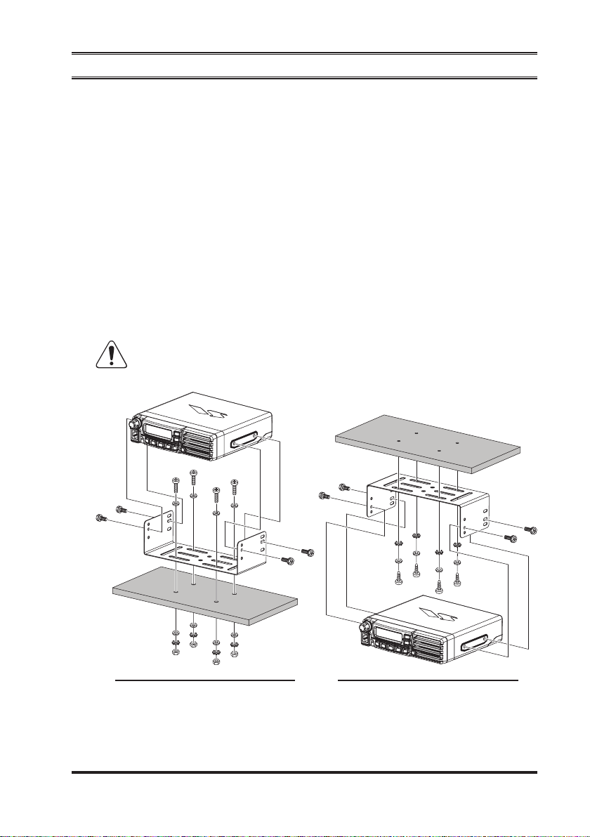
The supplied mounting bracket allows desktop or overhead mounting.
Use a 7/32 inch (5.5 mm) bit to drill the holes to a surface which is more 0.4
r
inch (10 mm) thick and can support more than 3.3 lbs (1.5 kg) and secure the
bracket with the supplied screws, spring washers, at washers, and nuts.
You may secure the bracket using the supplied tapping screws, instead of the
screws and nuts. In this case, drill the small pilot holes instead of the 7/32 inch
(5.5 mm) holes.
Install the transceiver to the bracket using the supplied Hex Head Bolts.
r
Use only the supplied Hex Head Bolts, or equivalent size screws
(HSM4X8B).
transceiver, make sure to plan the installation care-
deskTOP MOunT
(
WiTh TAPPing sCreW
)
OverheAd MOunT
(
WiTh sCreW & nuT
)
9
Page 12
VX-7200 SerieS Operating Manual
insTAllATiOn
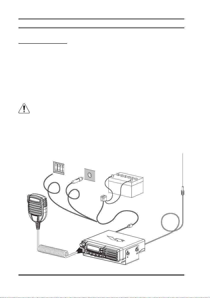
Mobile Installation
Power connection
VX-7200
starting the installation, make sure that the ground polarity of the vehicle is correct. Accidentally reversing the polarity will not damage the transceiver, but will
cause the cable fuses to blow.
To minimize voltage drop and avoid blowing the vehicle’s fuses, connect the supplied DC power cable directly to the battery terminals. Do not attempt to defeat or
bypass the DC cable’s fuse - it is there to protect you, your transceiver, and your
vehicle’s electrical system.
15-A fuse. Failure to observe these safety precautions will void the Limited Warranty on this product.
r
transceiver operates only in negative ground electrical systems. Before
Warning! Never apply AC power to the power cable of the transceiver, nor
DC voltage greater than 15.8 Volts. When replacing the fuse, only use a
Before connecting the transceiver, check the voltage at the battery terminals
while revving the engine. If the voltage exceeds 15 Volts, adjust the vehicle’s
voltage regulator before proceeding with installation.
Fuse Box
Ò
Cigarette Lighter Plug
Ò
12 V Battery
10
(
RED: POSITIVE (+) Terminal
BLACK: HEGATIVE
Mobile Antenna
See next page for details
(–)
Terminal
)
Page 13
VX-7200 SerieS Operating Manual
insTAllATiOn
Connect the RED power cable lead to the POSITIVE (+) battery terminal,
r
and the BLACK power cable lead to the NEGATIVE
need to extend the power cable, use #12 AWG or larger insulated, stranded
copper wire. Solder the splice connections carefully, and wrap the connections
thoroughly with insulating electrical tape.
Wire the cable so that not to disturb with the driving.
r
Before connecting the cable to the transceiver, verify the voltage and polarity
r
of the voltage at the transceiver end of the DC cable using a DC voltmeter.
Now connect the transceiver to the DC cable.
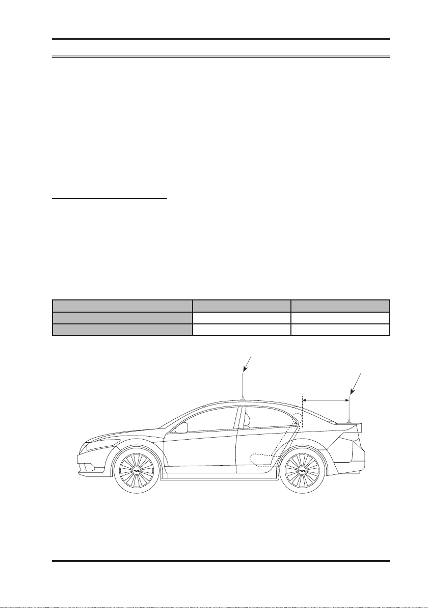
AntennA instAllAtion
The mobile antenna installation is limited to metal body motor vehicles or vehicles
with appropriate ground planes.
Antennas mounted on the trunk should be located at least the following distance
away from operator and passengers in order to comply with the FCC/IC RF exposure requirements. If can not meet these requirements, the antenna must be placed
in the center of the roof.
Required Distances
VHF Model UHF Model
FCC RF Exposure Requirements
IC RF Exposure Requirements
1.64 Feet (0.5 m
5.12 Feet (1.56 m
)
)
(–)
terminal. If you
1.38 Feet (0.42 m
4.17 Feet (1.27 m
)
)
If can not meet the above distance at the trunk lid mount,
the antenna must be placed in the center of the roof.
Roof Top Mount
Should be located at the
above distance or more.
Trunk Lid Mount
11
Page 14
VX-7200 SerieS Operating Manual
insTAllATiOn
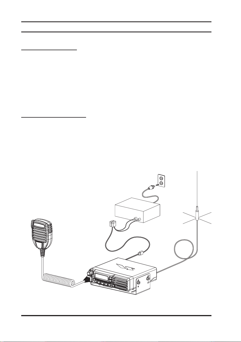
Base Station Installation
Power connection
Operation of the
VX-7200
capable of providing at least 15 Amps continuously at 13.6 Volts DC. Please contact your dealer to select an optimal power supply that satisfy these requirements.
Use the supplied DC power cable for making power connections to the power
supply. Connect the RED power cable lead to the POSITIVE (+) power supply
terminal, and connect the BLACK power cable lead to the NEGATIVE
supply terminal.
AntennA instAllAtion
When used the
must comply with the following requirements in order to ensure optimal performance and compliance with the RF energy exposure limits in the standards and
guidelines.
The antenna should be mounted outside the building on the roof or a tower if
r
at all possible.
VX-7200
transceiver from an AC line requires a power supply
(–)
power
transceiver as a base station, the antenna installation
AC Outlet
12
AC Power Supply
(
13.6 V, 15 A
)
Antenna
RED: POSITIVE (+) Terminal
BLACK: HEGATIVE
(–)
Terminal
Page 15

VX-7200 SerieS Operating Manual
insTAllATiOn
As with all xed site antenna installations, it is the responsibility of the licens-
r
ee to manage the site in accordance with applicable regulatory requirements
and may require additional compliance actions such as site survey measurements, signage, and site access restrictions in order to insure that exposure
limits are not exceeded.
13
Page 16
VX-7200 SerieS Operating Manual
COnTrOls & COnneCTOrs
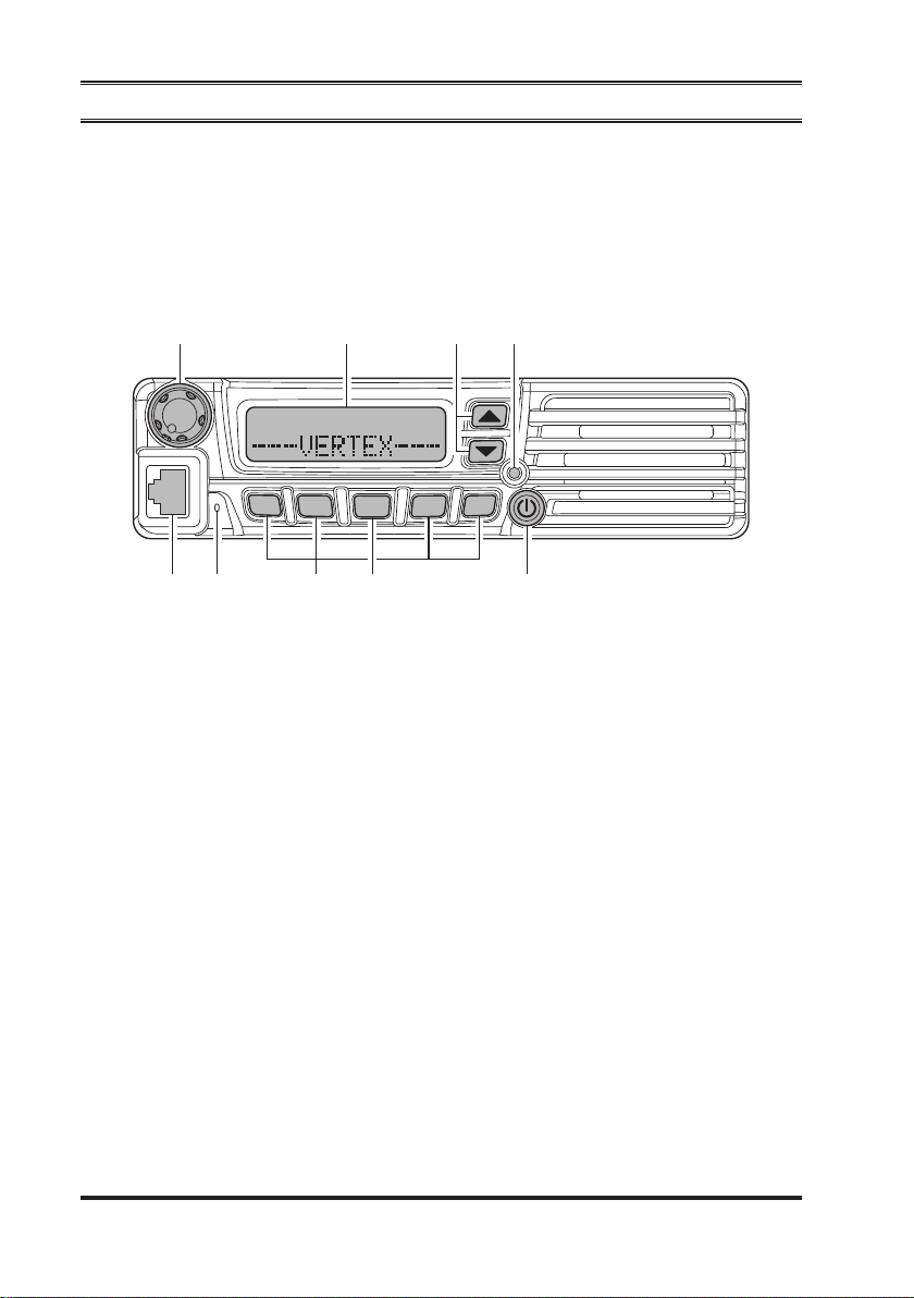
Front Panel
Important! - All buttons located on the Front Panel are Programmable Function (PF) Buttons, configured according to your network requirements and
programmed by your Vertex Standard dealer. The instructions below describe a
typically-congured radio.
P1
VOL Knob
Turn this control clockwise to increase the volume.
Microphone Jack
Connect the microphone plug to this jack.
Emergency Microphone
The emergency microphone is located behind this small slit. When the emer-
gency feature is activated, this microphone is enabled.
[P1] - [P4]
These buttons can be set up for special applications, such as High/Low power
selection, Monitor, Talk-Around, etc., as determined by your network requirements and programmed by your Vertex Standard dealer.
Buttons (Programmable Function Buttons
P2
P4
P3
A
)
[A]
This button can be set up for special applications, such as High/Low power
14
Button (Programmable Function Button
selection, Monitor, Talk-Around, etc., as determined by your network requirements and programmed by your Vertex Standard dealer.
)
Page 17
VX-7200 SerieS Operating Manual
COnTrOls & COnneCTOrs
(POWER) Button
Press and hold in this button for 2 seconds to toggle the transceiver’s power
“on” and “off.”
BUSY/TX Indicator
Indicates transceiver’s Transmit/Receive Status
Steady Red: Transmitting in progress
Steady Green: Signaling Off
Blinking Green: Busy Channel/Squelch Off
[]/[]
Buttons (Programmable Function Buttons
)
Pressing either button changes the current channel (and displayed channel
number or name). Holding in either button for more than 1.5 second causes
the radio to begin stepping (repeatedly) upward or downward through the
channels.
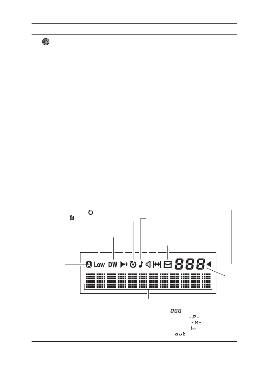
LCD (Liquid Crystal Display
)
The display includes a 3-character numeric section showing Channel Group
number or certain status indications (see below), a 12-character alpha-numeric
section showing Channel name tags/identity information and error messages,
and an upper icon row displaying feature status.
Group Scan
Scan
: “
Priority Scan
: “
Horn Alert
“
Dual Watch
“
Low Transmt Power Mode “ON”
” is enabled
” is activated
” is activated
” is activated
Call
“
” indicator
Receiver Monitor
Talk-Around
“
Voice Message
“
“
” is enabled
” is enabled
” received
12 Character Alpha-numeric Display
Analog Transmission
“
” is activated
: Channel Group Number
: ARTS “
: ARTS “
Sub-LCD
: Priority Channel
: Home Channel
In Range
Out of Range
15
”
”
Page 18
VX-7200 SerieS Operating Manual
COnTrOls & COnneCTOrs
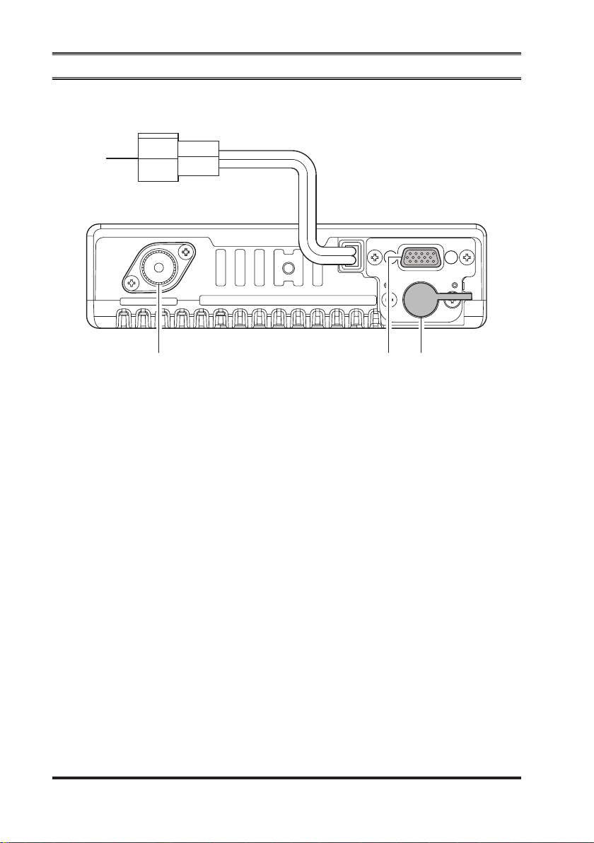
Rear Panel
13.6V DC Cable Pigtail with Connector
The supplied DC power cable must be connected to this 2-pin connector. Use
only the supplied fused cable, extended if necessary, for power connection.
Antenna Socket
The 50-Ohm coaxial feedline to the antenna must be connected here, using a
type-M (PL-259) plug.
D-Sub 15-Pin Accessory Connector
External TX audio line input, PTT (Push To Talk), Squelch, and external RX
audio line output signals may be obtained from this connector for use with accessories such as data transmission/reception modems, and external Channel
control input etc.
External Speaker Jack
An external loudspeaker may be connected to this 2-contact, 3.5-mm mini-
phone jack.
Caution: Do not connect either wire of this line to ground, and be certain that
the speaker has adequate capability to handle the audio output (12 W) from
the radio.
16
Page 19

VX-7200 SerieS Operating Manual
BAsiC OPerATiOn OF The TrAnsCeiver
Important! - Before turning on the radio the rst time, conrm that the power connections have been made correctly and that a proper antenna is connected to the
antenna jack.
Switching Power ON/OFF
Press and hold in the
r
The display will become illuminated.
Press the
r
name will appear on the display. If you want to select an operating channel
from a different group, press the PF (Programmable Function) button which is
programmed to the Group Up/Down feature to select the group you want before selecting the operating channel. See page 19 for more information on the
Programmable Function keys.
[]/[]
(
POWER
button to choose the desired operating channel. A channel
Setting the Volume
Turn the
r
to decrease it.
knob clockwise to increase the volume, and counterclockwise
VOL
Transmitting
To transmit, monitor the channel and make sure it is clear.
r
THIS IS AN FCC REQUIRMENT!
Press the PF button which is programmed to the Monitor feature to listen for
r
channel activity.
When receiving a call, transmit only after the incoming call ends. The radio
r
cannot receive a call and transmit simultaneously.
Press the
r
If the channel is clear, the
r
now transmitting. While holding in the
the microphone in a clear and normal voice. For best transmission, hold the
microphone about 1-1/2 to 2 inches away from your mouth. Release the
switch to receive.
If the Busy Channel Lockout feature has been programmed on a channel, the
r
radio will not transmit when a carrier is present. Instead, the radio will gener-
ate a short beep three times and indicate “*
lease the
If CTCSS or Digital Coded Squelch (DCS) Lockout has been programmed on
r
a channel, the radio can transmit only when there is no carrier being received or
when the carrier being received includes the correct CTCSS tone or DCS code.
switch.
PTT
switch and wait for the channel to be clear of activity.
PTT
)
button for 2 seconds to turn the radio on.
BUSY/TX
indicator will glow red. The radio is
switch, speak across the face of
PTT
PTT
ERROR
*” on the display. Re-
17
Page 20

VX-7200 SerieS Operating Manual
BAsiC OPerATiOn OF The TrAnsCeiver
Automatic Time-Out Timer
If the selected channel has been programmed for automatic time-out, you must
limit the length of each transmission. While transmitting, a beep will sound 10 seconds before time-out. Another beep will sound just before the deadline; the red “TX”
indicator will disappear and transmission will cease soon thereafter. To resume
transmitting, you must release the
expire (if you press the
and you will have to wait another “penalty” period)
switch before this timer expires, the timer restarts,
PTT
Key Lock
In order to prevent accidental frequency change or inadvertent transmission, various aspects of the
cise lockout conguration may be congured using the “User Set” (Menu) mode.
See page 16 for detail.
VX-7200
’s keys, and
switch and wait for the “penalty timer” to
PTT
switch, may be locked out. The pre-
PTT
To activate the Locking feature, press and hold in the
radio on. To disable the Locking feature, repeat this power-on procedure.
[P4]
key while turning the
18
Page 21
VX-7200 SerieS Operating Manual
AdvAnCed OPerATiOn
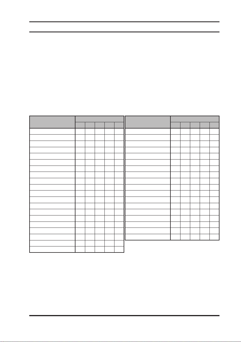
Programmable Function (PF) Buttons
The
VX-7200
button functions can be customized, via programming by your Vertex Standard
PF
dealer, to meet your communications/network requirements. Some features may
require the purchase and installation of optional internal accessories. The possible
button programming features are illustrated below, and these functions are ex-
PF
plained on the pages to follow.
For further details, contact your Vertex Standard dealer. For future reference,
check the box next to the function that has been assigned to each PF button on
your particular radio, and keep it handy.
Series includes seven Programmable Function (PF) Buttons. The
Function
MONI
SQL
DIMMER
Channel Up
Channel Down
Group Up
Group Down
Scan
DW (Dual Watch
Follow-Me Scan
Follow-Me DW
LOW
TA (Talk Around
Emergency
CALL/RESET
CALL 1
CALL 2
CALL 3
CALL 4
CALL 5
PF Button
A P1 P2 P3 P4
)
)
Function
Code Up
Code Down
Code SET
Speed Dial
HOME
Selectable Tone
Horn Alert
Public Address
EXT. ACC1
EXT. ACC2
Direct CH#1
Direct CH#2
Direct CH#3
Direct CH#4
AF Min Vr
SET
Individual Call
TX Mode
PF Button
A P1 P2 P3 P4
19
Page 22

VX-7200 SerieS Operating Manual
AdvAnCed OPerATiOn
Description of Operating Functions
Monitor (Moni
Press the assigned PF key to cancel CTCSS- and DCS-controlled squelch; the
BUSY/TX
to hear background noise (unmute the audio); the
green.
indicator will glow green. Press and hold in this button for 1.5 seconds
)
BUSY/TX
indicator will blink
squelch (sql
You can manually adjust the squelch level using this function:
Press the assigned PF key. A tone will sound, and the current squelch will
r
level appears on the display.
Press the
r
Press this key again. A tone will sound, and the display will revert to the nor-
r
mal channel indication.
)
[]/[]
button to select the desired squelch level.
diMMer
Press the assigned PF key to select the brightness level of the display and key
backlight. Available selections are four levels.
chAnnel uP/down
Press the assigned PF key (generally the
channel within the current group.
[]/[]
button) to select a different
GrouP uP/down
Press the assigned PF key to select a different group of channels. Once the desired
Group is reached, press the Channel Up/Down key (generally the
to select the desired channel within the selected Group.
You may wish to have the Scanner pass through more than one Group during the
scanning process (normally, scanning is performed within the current group only).
To include the current Group in the scanning loop, press and hold in the assigned
key for one second. To remove a Group from Group Scan, press and hold in
PF
the assigned PF key again for one second.
[]/[]
button)
Multi-Group Scanning is only possible if you are using the “User Scan” list. To
edit the User Scan list, press and hold the assigned PF key for one second to delete the current Memory Group from the Scanning. Alternatively, press and hold
the assigned PF key for one second to delete the Current Memory channel from
the Scanning. When you delete a Group or channel, “
on the LCD for one second after pressing the assigned PF key. To restore a partic-
20
-
SCAN Skip
-
” will appear
Page 23

VX-7200 SerieS Operating Manual
AdvAnCed OPerATiOn
ular channel to your scanning list, press and hold in the assigned PF key again for
one second; “
ing the assigned PF key.
-
SCAN Stop
-
” will appear on the LCD for one second after press-
chAnnel scAn (scAn
The Scanning feature is used to monitor multiple channels programmed into the
transceiver. While scanning, the transceiver will check each channel for the presence of a signal, and will stop on a channel if a signal is present.
To activate scanning:
Press the assigned PF key to activate scanning on the current group.
r
The scanner will search the programmed channels, looking for active ones; it
r
will pause each time it nds a channel on which someone is speaking.
Press the assigned PF key again to disable scanning. Operation will revert to
r
the programmed revert channel or activate the Group scanning when MultiGroup Scanning is enabled.
Note: Your dealer may have programmed your radio to stay on one of the fol-
lowing channels if you press the
Current channel (“Talk Back”)
“Last Busy” channel
“Priority” channel
“Home” channel
“Scan Start” channel
duAl wAtch (dw
The Dual Watch feature is similar to the SCAN feature, except that only two channels are monitored:
The current operating channel; and
The Priority channel.
)
switch during the scanning pause:
PTT
)
To activate Dual Watch:
Press the assigned PF key.
r
The scanner will search the two channels; it will pause each time it nds a
r
channel on which someone is speaking.
To stop Dual Watch:
Press the assigned PF key.
r
Operation will revert to the “Dual Watch Start” channel.
r
21
Page 24

VX-7200 SerieS Operating Manual
AdvAnCed OPerATiOn
Follow-Me scAn
“Follow-Me” Scan feature checks a User-assigned Priority Channel regularly as
you scan the other channels. Thus, if only Channels 1, 3, and 5 (of the 8 available
channels) are designated for “Scanning,” the user may nonetheless assign Channel
2 as the “User-assigned” Priority Channel via the “Follow-Me” feature.
To activate “Follow-Me” scanning, rst select the channel you want to designate
as the “User-Assigned Priority Channel” and press the assigned PF key. Then
press the Channel Up/Down key (generally the
“Scanning Start” channel which has been programmed by your dealer to activate
the scanner. When the scanner stops on an “Active” channel, the User-assigned
Priority Channel will automatically be checked every few seconds; if activity is
found on the User-assigned Priority Channel, the radio will switch between it and
the Dealer-Assigned Priority Channel, if any.
[]/[]
button) to recall to the
Follow-Me duAl wAtch (dw
To set up a “Dual Watch” frequency pair using the “Follow-Me” feature, select a
channel using the Channel Up/Down key (generally the
press the assigned PF key; pressing the assigned PF key locks the current channel as the User-assigned Priority Channel. Now press the Channel Up/Down
key to select another channel (not the “Scanning Start” channel). Your radio will
now switch back-and-forth between the currently-selected channel and the Userassigned Priority Channel.
During “Follow-Me” scanning (after you have pressed the key), you can set up the
“Dual Watch” feature by pressing the Channel Up/Down key to another channel.
The radio will then scan back and forth between the original User-assigned Priority Channel and the newly-selected channel.
The Priority Channel you have assigned (before pressing the key) will be retained
in memory until you change it.
low Power (low
Press the assigned PF key to set the radio’s transmitter to the “Low Power” mode,
thus extending battery life. Press the PF key again to return to “High Power” operation when in difcult terrain.
When the radio’s transmitter is set to “Low Power” mode, the “ ” icon will be
indicated on the display.
)
)
[]/[]
button). Now
22
Page 25

VX-7200 SerieS Operating Manual
AdvAnCed OPerATiOn
tAlk Around (tA
Press the assigned PF key to activate the Talk Around feature when you are operating on duplex channel systems (separate receive and transmit frequencies,
utilizing a “repeater” station). The Talk Around feature allows you to bypass the
repeater station and talk directly to a station that is nearby. This feature has no effect when you are operating on “simplex” channels, where the receive and transmit
frequencies are already the same.
When the “TA” function is activated, the “ ” icon will be indicated on the display.
Note that your dealer may have mode provision for “Talk Around” channels by
programming “repeater” and “Talk Around” frequencies on two adjacent channels.
If so, the key may be used for one of the other Pre-Programmed Functions.
eMerGency
The
VX-7200
have someone monitoring on the same frequency as your transceiver’s channel.
Press the assigned PF key to initiate an emergency call. For further details contact
your Vertex Standard dealer.
series include an “Emergency” feature which may be useful if you
cAll/reset
This feature, if enabled, allows the user to change the 3-digit Page Call code, used
to call other similarly-equipped stations. Press the assigned PF key, followed by
the three digits representing the Page Call code of the station you wish to call.
Three tones will be heard after the last key is pressed (the new code will now be
transmitted).
)
The receiver squelch of the other station will be opened, and you can begin communication.
cAll 1 to cAll 5
Press the assigned PF key to send a 2-Tone sequential burst which is pre-dened.
code uP/down
Press the assigned PF key to select a 2-Tone encode code from pre-dened encode
list.
23
Page 26
VX-7200 SerieS Operating Manual
AdvAnCed OPerATiOn
code set
Press the assigned PF key to change the 2-Tone encoding digit. To change the
tones, select the desired digit using the
using the
[]/[]
keys.
sPeed diAl
Your Dealer may have pre-programmed Auto-Dial telephone number memories
into your radio.
To dial a number, press the assigned PF key, then press the microphone’s numbered key corresponding to the Auto-Dial memory number list provided by your
Dealer. The DTMF tones sent during the dialing sequence will be heard in the
speaker.
[P1]/[P2]
keys, then change the number
hoMe chAnnel (hoMe
Press the assigned PF key to recall the pre-dened Home group/channel. When
you recall the Home group/channel, the “ ” icon will appear on the LCD.
)
selectAble tone
Press the assigned PF key to select a sub-audible tone (CTCSS/DCS) from the
pre-dened tone table. You can operate the indicated sub-audible tone in Selectable Tone mode.
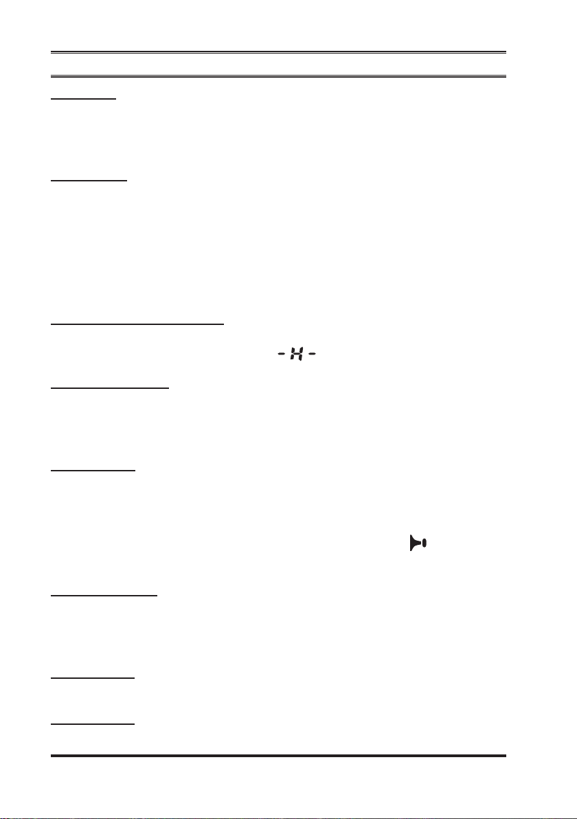
horn Alert
Press the assigned PF key to turn the Horn Alert function “ON” or “OFF.” If you
receive a call from the base station with 2-Tone or DTMF signaling, horn alert will
be activated and your vehicles horn will sound.
When you turn the Horn Alert “ON,” a tone will sound and the “ ” icon appears
will appear on the display.
Public Address
Press the assigned PF key to use the transceiver as a PA amplier. When you enable this function, a tone sounds and “
The public address can be used even while scanning and receiving a call.
Public ADRS
” will appear on the display.
EXT. ACC1
Press the assigned PF key to toggle output port on “1” “on” and “off.”
eXt. Acc2
Press the assigned PF key to toggle output port on “2” “on” and “off.”
24
Page 27

VX-7200 SerieS Operating Manual
AdvAnCed OPerATiOn
direct ch#1 to direct ch#4
Press the assigned PF key to recall the Dealer pre-programmed channel directly.
AF Min Vr
Press the assigned PF key to reduce the audio output to the (lower) level programmed by your Dealer.
set
Press the assigned PF key to activate the “User Set” (Menu) Mode.
indiViduAl cAll
Press the assigned PF key to enable the Individual Calling on the APCO Project
25 Digital System.
To return to the Group Calling on the APCO Project 25, press again the assigned
key.
tX Mode
Press the assigned PF key to select the TX mode. Available selections are:
TX Mixed: The
the analog signal. Meanwhile, the
tal Mode, when after receiving the digital signal.
TX Digital: The
TX Analog: The
VX-7200
VX-7200
VX-7200
transmits in the Analog Mode, when after receiving
VX-7200
transmits in the Digital Mode.
transmits in the Analog Mode.
transmits in the Digi-
25
Page 28

VX-7200 SerieS Operating Manual
AdvAnCed OPerATiOn
ARTS (Auto Range Transpond System)
This system is designed to inform you when you and another ARTS-equipped station are within communication range.
During ARTS operation, when the radio receives an incoming ARTS signal, a short
beep will sound, and “ ” (“In Service”) will be displayed on the sub-LCD. If you
move out of range for more than two minutes, your radio senses that no signal has
been received; a short triple-beep will sound, and “ ” (“Out of Service”) will
be displayed on the Sub-LCD. If you subsequently move back into communication
range, as soon as the other station transmits, a short beep will sound and “In” will
be displayed again on the Sub-LCD.
DTMF Paging System
This system allows paging and selective calling, using DTMF tone sequences.
When your radio is paged by a station bearing a tone sequence which matches
yours, your radio’s squelch will open and the alert will sound. The three-digit code
of the station which paged you will be displayed on your radio’s LCD.
MDC1200® Encoding
Generally MDC1200® Data Burst is a type of ANI.
It can be used to identify the calling radio or emergency call, and also use to control special functions of the receiving radio.
RSSI Beep
This feature allows you to inform the Receiving Signal Level while operating on
the APCO Project 25 Digital System.
When the Receiving Signal Level is weaken, the alert will sound every one second.
When the Receiving Signal Level is weaken still more, the alert will sound every
1/2 second.
Caller ID Display
This feature is available on the APCO Projetct 25 Digital System.
The Caller ID will appear on the LCD display when receiving Unit to Unit call
(Paging).
Caller ID: Tag information will appear when receiving the Source ID which
listed at the Destination ID table on your radio, otherwise received
Source ID will appear.
26
Page 29
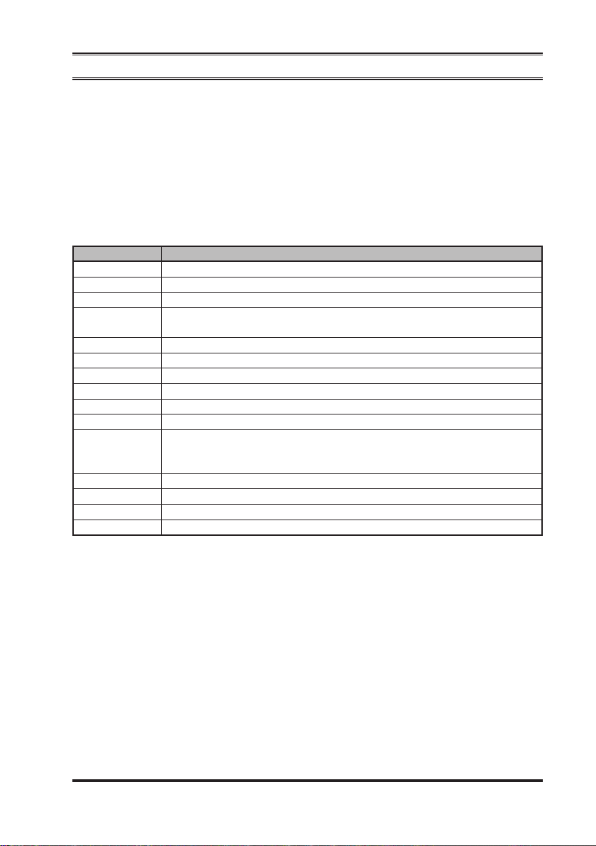
VX-7200 SerieS Operating Manual
user seT MOde
The
VX-7200
to dene or congure various settings, such as Squelch, Display contrast, etc. To
activate the “User Set” (Menu) Mode:
Series includes a “User Set” (Menu) Mode which allows the user
Press the PF key assigned to the “
r
Select the User Set Mode item you wish to change using the
r
then use the
Press the
r
Press
r
Display Description
1 SQL
2 SCN List
3 BEEP
4 BELL
5 Lighting
6 Lock
7 Group
8 SCAN
9 DW
10 TA
11 RSSI BEEP
12 AF Min VR
13 Beep VR
14 Contrast
15 Dimmer
Note: RSSI BEEP operates in APCO Project 25 Digital System.
[]/[]
[P1]
[A]
key to exit to normal operation.
Sets the Squelch Level.
Select the “User” or “Dealer” Scan List.
Enables/Disables the Key Beeper.
Enables/Disables the Bell function.
(alert tone activated by incoming subaudible CTCSS/DCS tone)
Enables/Disables the
Set the Control Key Lockout Coguration (Key/PTT/Key+PTT).
Select the desired Channel Group.
Engages/Disengages Scanning (same as the programmable
Engages/Disengages Dual Watch (same as the programmable
Engages/Disengages Talk Around (same as the programmable
Enables/Disables the disabling the RSSI beep.
on
off
Sets the minimum Audio Volume level.
Sets the Beep Volume level.
Sets the LCD Contrast level.
Sets the brightness of the backlighting of the key and LCD.
keys to adjust the setting of the selected item.
[P2]
or
: Enables the disabling the RSSI beep.
: Disables the disabling the RSSI beep.
key to store the new conguration.
BUSY/TX
SET
” function.
LED.
[P1]/[P2]
[
SCAN
[DW]
[TA]
keys,
]
key).
key).
key).
27
Page 30

OPTiOnAl ACCessOries
MD-12A8J Desktop Microphone
MH-67A8J Standard Microphone
MH-75A8J DTMF Keypad Microphone
MLS-100 Mobile Loudspeaker (12 W Peak Power)
MLS-200 Mobile Loudspeaker (12 W Peak Power/Waterproof)
LF-1 Line Filter
CE76 Programming Software
FIF-12 USB Programming Kit
CT-104A Connection Cable for FIF-12
Availability of accessories may vary; some accessories are supplied standard per
local requirements, others may be unavailable in some regions.
Check with your VERTEX STANDARD Dealer for changes to this list.
WArrAnTy POliCy
Vertex Standard warrants, to the original purchaser only, its Vertex Standard manufactured communications products against defects in materials and workmanship
under normal use and service for a given period of time from the date of purchase.
Limited Warranty Details:
North America customers (USA and Canada):
http://www.vertexstandard.com/lmr/warranty-terms.aspx
Customers outside of North America:
Contact the authorized dealer in your country.
VX-7200 SerieS Operating Manual28
Page 31

Part 15.21: Changes or modications to this device not expressly
approved by Vertex Standard could void the user’s authorization to
operate this device.
Page 32

No portion of this manual may be reproduced without the permission of Vertex Standard LMR, Inc.
Vertex Standard is a trademark of Vertex Standard LMR, Inc.
All other trademarks are the property of their respective owners.
©2015 Vertex Standard LMR, Inc.
All rights reserved.
Printed in Japan
 Loading...