

Page 1

PWC – 7000
PureWaterCooler
SERVICE MANUAL
for
PureWaterCooler
by Vertex
Model 7000
™
Copyright 2012 Vertex Water Products
Page 2

PWC – 7000
PureWaterCooler
Table of Contents
1. Introduction
2. Cooler Set-up
3. Top Cover Removal
4. Remove/Replace Mechanical Float Valve Assembly
5. Removing/Replacing Control Panel and Circuit Board
6. Remove/Replace Hot Tank
7. Remove/Replace Spigot Internals
8. Draining Cooler Tanks
9. Remove/Replace Hot Tank Sensor
10. Remove/Replace Cold Temperature Switch and Sensor
11. Sanitization Procedure
12. Trouble Shooting
13. Specifications
14. Cooler Exploded View
15. Parts List
16. Schematics
Copyright 2012 Vertex Water Products
Page 3

PWC – 7000
PureWaterCooler
PWC-7000 Cooler
1. Introduction
The PWC-7000 line of point of use coolers are designed to give years of reliable service
The cooler has 2 spigots that dispense filtered water at 2 different temperature levels – hot
and cold temperature water. The cold tank holds 1.1 gallons of water and is
constructed of stainless steel. The main (room-temp) tank holds 4.4 gallons of water and can
be accessed for servicing the float mechanism and for cleaning by removing the cooler main
top cover (see section 3).
The hot tank is made of stainless steel and holds 1.0 gallons. It is important not to turn on the
hot tank when there is no water in it as this will damage the heating element.
The compressor is a sealed unit and is not serviceable in the field. The compressor can be
replaced by a qualified refrigeration technician with proper tools and equipment.
Please consult the factory if the compressor needs servicing.
CAUTION: If the compressor has been stopped by switching it off or unplugging power,
WAIT 10 MINUTES before turning the compressor on again. The compressor may stall
and burnout if powered back on without waiting.
The cooler makes clean water by filtration or by the reverse osmosis process. Water enters the
back of the cooler and then passes through the filtration system. A feed water ball valve is
located near the filters and must be turned to the on position to allow the unit to make water.
Electrical power is not required for the cooler to make purified water. CAUTION: The carbon
filtration versions of the cooler (PWC-7000F) should not be used with water hardness over
7 grains because of lime scale build up on the heating element. If hardness is higher than
7 grains, softening of the feed water is recommended or another option is to install
a “phosphate” filter to the filter system.
Copyright 2012 Vertex Water Products
Page 4
PWC – 7000
PureWaterCooler
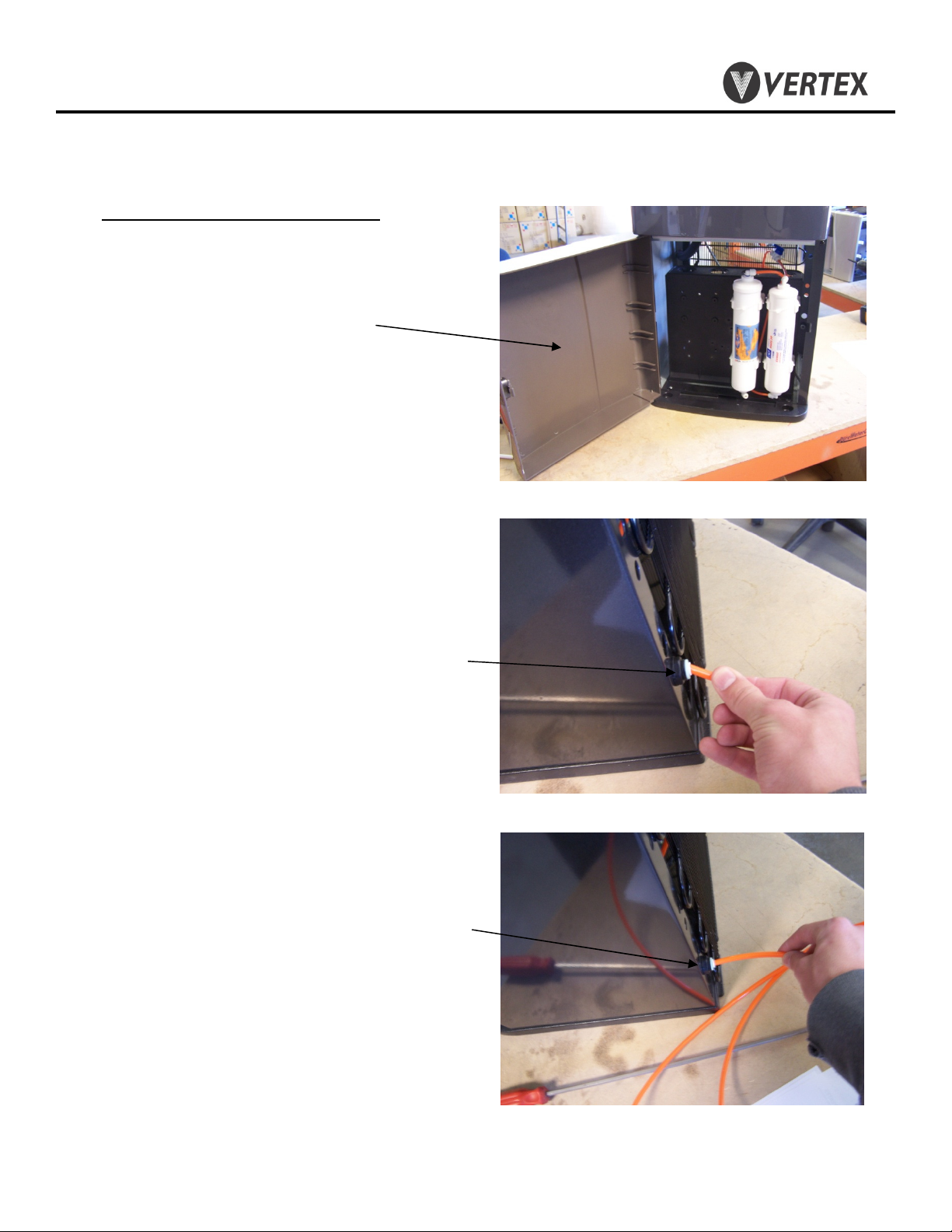
2. Cooler Set-Up (for new cooler installation)
Feedwater/Drain Connections
-Feed Connection
2.1 Open hinged door to access filter
compartment
2.5 Remove feed water plug (orange) from back
of cooler.
2.6 Connect supplied orange feed water tubing to
feed connector on back of cooler.
Copyright 2012 Vertex Water Products
Page 5

PWC – 7000
PureWaterCooler
2. Cooler Set-Up
2.4 Make feed water connection to cold water line.
A self piercing saddle valve is provided.
2.5 Flushing carbon fines from carbon filter.
Most carbon filters have fine particles of
carbon material in the filter that will be
swept into the water stream when the first
water flows through the filter. Although not
harmful, these carbon fines in the water are
unsightly. Flush the carbon fines out of the
filter before filling cooler tanks with the
following procedure.
cont.
Feedwater connection (RO & filtration coolers
(For use on copper tubing)
Use supplied self piercing saddle valve.
Connect to water inlet on cooler using 1/4”
tubing. Clamp saddle valve over copper feed
water line (cold water line only). Tighten
needle valve until tube is pierced. Retract
needle 1 -2 turns to start water flow.
)
2.6 Remove outlet line of carbon filter (bottom)
2.7 Attach 3 feet of ¼” tubing to the carbon filter
outlet port (flush tubing)
2.8 Place flush tubing in bucket to catch water
carbon fines.
Copyright 2012 Vertex Water Products
Page 6
PWC – 7000
PureWaterCooler
2. Cooler Set-Up
2.9 Turn on feed water at source and turn ball valve
at filter to “on” to let the water flush the filter.
2.10 Flush until water flows clear (1 – 2 gallons)
2.11 Remove flush line. Reconnect tank line to
outlet of carbon filter
2.12 WARNING: Do not turn on cooler hot power
until cooler tanks are full of water.
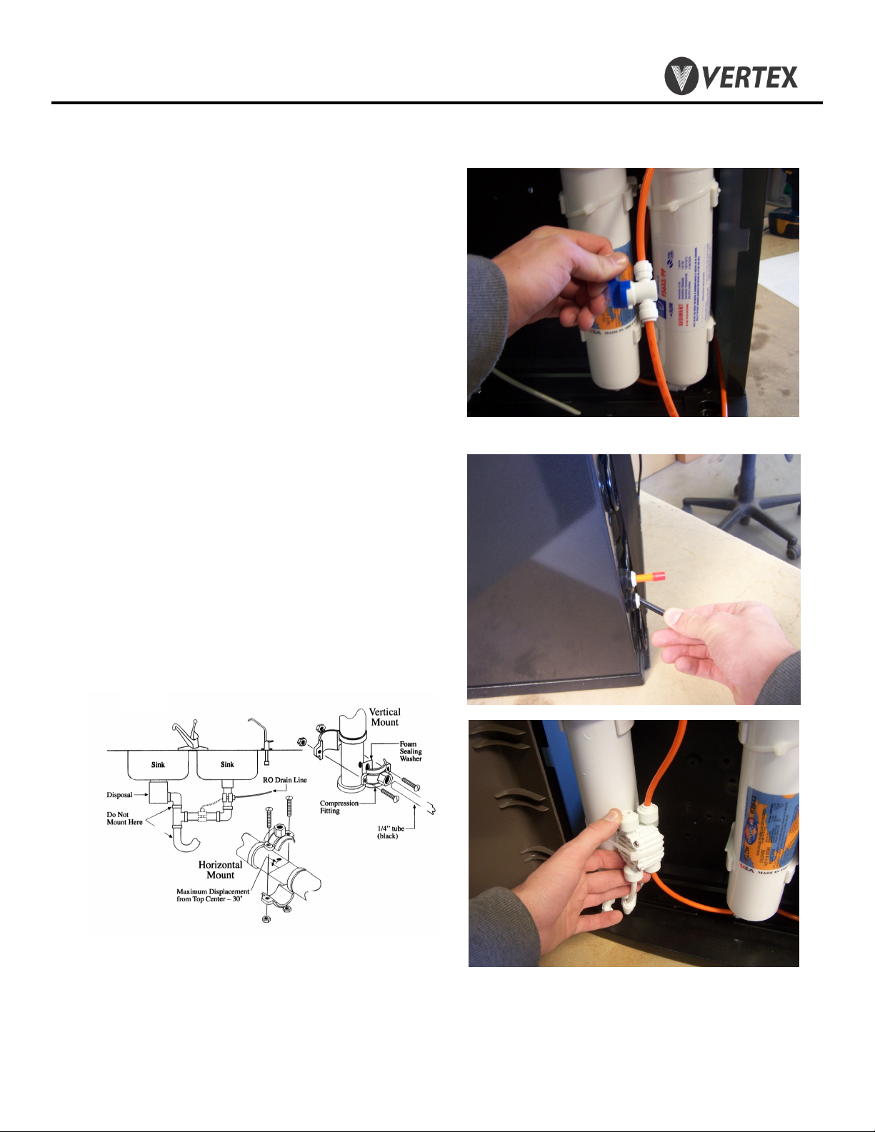
-Drain Connection
2.9 Drain Connection (for units equipped
with RO)
2.10 Remove drain plug (black) from back of
cooler
cont.
Figure 2.7
2.11 Connect supplied black tubing to
drain connector on back of cooler
2.12 Attach supplied drain saddle to a
standard 1 ½” drain pipe see fig. 1 below
Drain saddle connection method
Drain connection required only for cooler with reverse osmosis filtration
Figure 1
RO filter set showing autovalve.
The autovalve automatically turns off the
water flow when the tanks are full
Copyright 2012 Vertex Water Products
Page 7
PWC – 7000
PureWaterCooler
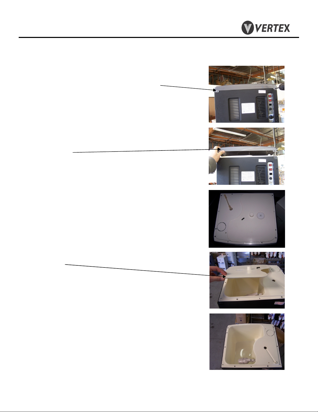
3. Top Cover Removal
3.1 Remove (2) screws on back of cooler top cover
3.2 Lift cover
3.3 Lift Lid
3.4 Room tank is now accessible for cleaning
and servicing other parts of the cooler.
3.5 Reinstall in reverse order
Copyright 2012 Vertex Water Products
Page 8
PWC – 7000
PureWaterCooler
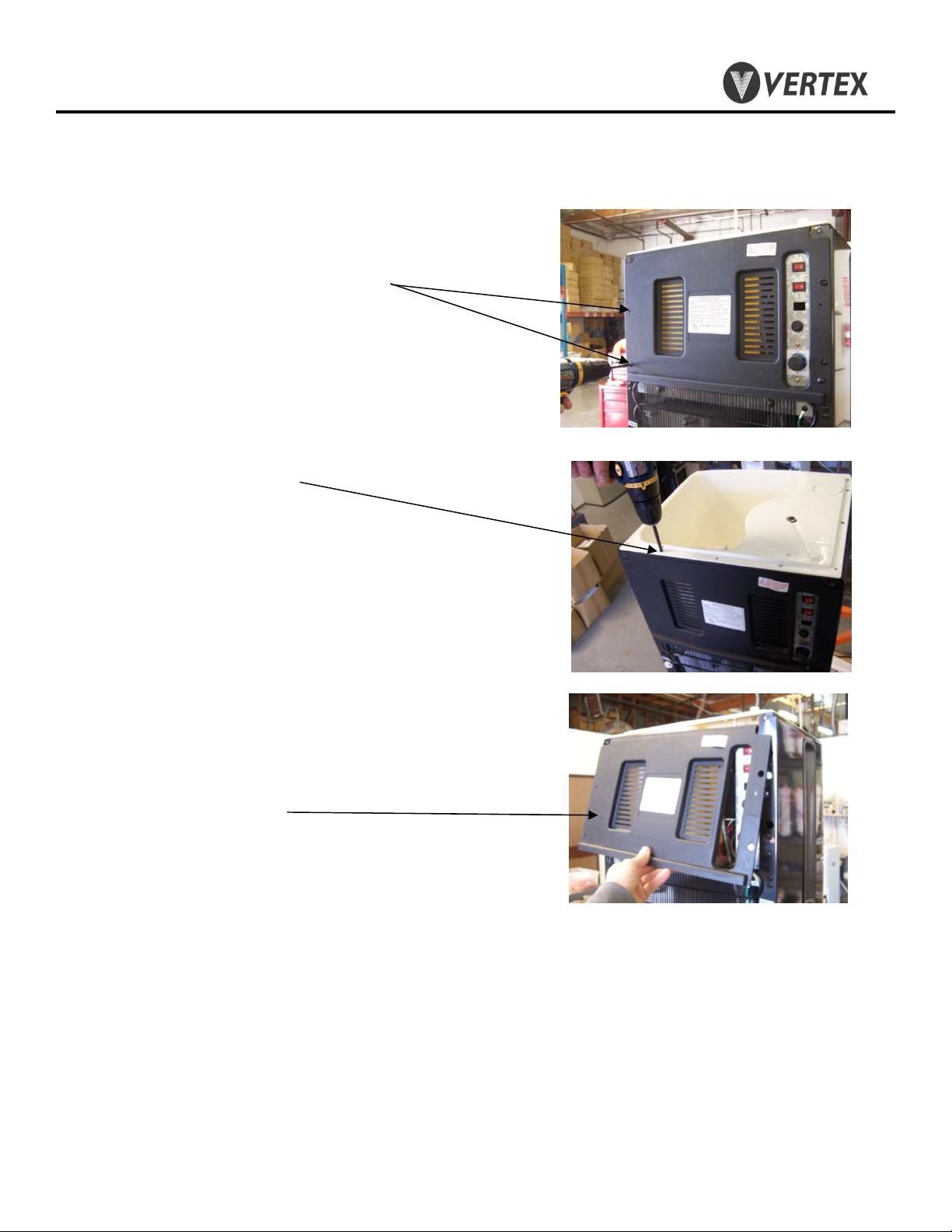
4. Remove/Replace Mechanical Float Valve Assembly
4.1 Remove top lids from cooler as
performed in Section 3.
Remove Black Screws (4)
4.2 Remove Silver Screws (2)
4.3 Remove Back Panel
Copyright 2012 Vertex Water Products
Page 9

PWC – 7000
PureWaterCooler
4. Remove/Replace Mechanical Float Valve Assembly
4.4 Remove ¼” elbow from stem.
4.5 Remove nut from float assembly.
This is easily done by turning the float
while holding the nut.
4.6 Remove float mechanism from
main tank.
4.7 Complete Float assembly
(removed)
4.8 Reassembled in reverse order.
Copyright 2012 Vertex Water Products
Page 10

PWC – 7000
PureWaterCooler
5. Removing/Replacing Control Panel and Circuit Board
5.1 Place hand under control panel and pull up and out.
5.2 Disconnect connector from circuit board.
5.3 Remove screw from circuit board.
Copyright 2012 Vertex Water Products
Page 11

PWC – 7000
PureWaterCooler
6. Remove/Replace Hot Tank
6.1 Follow proper procedures for removing
float valve assembly as described in Section
4.
6.2 Remove control panel as in Section 5.
(Disconnecting wire not necessary)
6.3 Remove silicon tube connected to hot
tank, easily accessible through the control
panel opening.
6.4 Remove cup-holder panel on left side of
cooler. Reach into the cabinet through the
control panel opening and apply pressure on
the side of the cup-holder panel as well as on
its rear. The cup-holder panel will unclip on
the left side as seen in the picture. Then pull
the panel to the left to free the panel from the
cooler.
Copyright 2012 Vertex Water Products
Page 12

PWC – 7000
PureWaterCooler
6. Remove/Replace Hot Tank
cont.
6.5 Remove silicon tube connected to bottom of hot
tank by reaching through the cup-holder panel
opening.
6.6 Remove 2 screws on top of hot tank.
6.7 Remove 9 screws mounting main tank.
Copyright 2012 Vertex Water Products
Page 13

PWC – 7000
PureWaterCooler
6. Remove/Replace Hot Tank
6.8 Remove two black screws.
cont.
6.9 Disconnect four electrical connectors and silicon
tube from hot tank. Do not disconnect electrical
connectors from components on bracket.
6.10 While gently lifting the main tank up, swing the
hot tank out of the cooler. When the electrical
connectors connected to the bottom of the hot tank
are exposed, reach in through the cup-holder
opening and disconnect them. The hot tank is now
free from the cooler.
6.11 Reassemble in reverse order.
Copyright 2012 Vertex Water Products
Page 14

PWC – 7000
PureWaterCooler
7. Remove/Replace Spigot Internals
7.1 Remove control panel as in Section 5.
7.2 Unscrew lever assembly from spigot
body and remove.
7.3 Reassemble in reverse order.
Copyright 2012 Vertex Water Products
Page 15

PWC – 7000
PureWaterCooler
8. Draining Cooler Tanks
Completely draining the tanks is required when shipping the cooler
or when one the of the tanks needs replacing. This procedure will
allow you to remove all the water from the cooler.
8.1 There are 3 ports located on the back of the
cooler (one for each tank)
8.2 For all ports, using a flat head screwdriver, pry
the plug out until you can grasp it with your
fingers.
8.3 Remove the plug with fingers. Water will
pour from the port.
8.4 Drain any remaining water in the
system by depressing the spigots.
Copyright 2012 Vertex Water Products
Page 16

PWC – 7000
PureWaterCooler
9. Remove/Replace Hot Tank Sensor
There are two thermal sensors on the hot tank. The lower sensor controls the heating
element function and the upper sensor is for high temperature cut out. If the hot tank
is not working, one or both of the sensors may have failed in the open position. To
check for this condition, unplug the cooler from main power, disconnect one of the
electrical terminals on the sensor. Using an ohm meter, check for continuity. If there
is no continuity, the sensor is bad and must be replaced.
9.1 Remove the top and back of the cooler per
section 3 to gain access to the hot tank.
9.2 The hot tank does not have to be removed from
the cooler to change the sensors. It is recommended
that the sensors be replaced one at a time so as to avoid
confusion when rewiring.
9.3 Remove the two screws that hold each sensor
to the tank. The sensor can now be removed.
9.4 Remove the electrical terminals from the sensor.
9.5 Reassemble in reverse.
Copyright 2012 Vertex Water Products
Page 17

PWC – 7000
PureWaterCooler
10. Remove/Replace Cold Temperature Switch and Sensor
The cold temperature switch includes the thermal sensor which is attached to
the switch. The sensor probe (integral with the switch ) is inserted into the
receptacle at the top of the cold tank.
10.1 With top and back cover removed,
remove adjustment knob using a flat
head screwdriver
10.2 Loosen (2) screws holding the switch
to the mounting plate.
Copyright 2012 Vertex Water Products
Page 18

PWC – 7000
PureWaterCooler
10. Remove/Replace Cold Temperature Switch and Sensor
cont.
10.3 Remove cup-holder panel as in section 6.
10.4 Carefully remove the sensor probe from the
receptacle at the top of the cold tank.
10.5 Disconnect (2) electrical terminal wires.
10.6 Lift and remove switch assembly from
cooler.
10.7 Replace new switch in reverse order.
Copyright 2012 Vertex Water Products
Page 19

PWC – 7000
PureWaterCooler
11. Sanitization Procedure
The sanitization procedure is performed to reduce/eliminate any bacteriological
growth in the cooler tanks and dispensing plumbing. Bacteriological growth
can be the cause of some taste in the water.
The procedure is as follows:
1. Mix ½ teaspoon of common household bleach (5.25%) with 5 gallons of
clean water.
2. Unplug the cooler from the power source.
3. Drain all water from the cooler tanks.
4. Pour the sanitizing solution into the main (room temperature) tank until full.
5. Open all 3 spigots to allow sanitizing solution to fill the dispensing faucets.
Close the faucets.
6. Let the sanitizing solution stand in the cooler for 10 minutes.
CAUTION: Leaving the sanitizing solution in the cooler for more
than 10 minutes can cause taste problems in the water.
7. Completely drain the sanitizing solution from all the tanks.
8. Fill the main (room temp.) tank with clear tap water to rinse out the
sanitizing solution.
9. Completely empty the rinse water from the tanks.
10. The cooler is now sanitized and ready for use.
Copyright 2012 Vertex Water Products
Page 20

PWC – 7000
PureWaterCooler
12. Trouble Shooting
Water not cold from cold tank
(Water dispenses from spigot but is not cold)
Possible causes Solution .
1. Cooler not plugged in Make sure power cord is plugged
into wall socket
2. Power switch not on Make sure cold power button on
on front panel is on
3. Adjust temperature control The thermostat temperature control
adjustment is located on the right
rear of the cooler
4. All cold water has been drained Cooler needs time to recover.
wait 10 minutes until water cools
5. Water not dispensing from Cold tank is frozen. Turn down
cold spigot cold temperature adjustment
Copyright 2012 Vertex Water Products
Page 21

PWC – 7000
PureWaterCooler
12. Trouble Shooting
Cont.
No Hot Water from Hot Tank
Possible Causes Solution
1. Cooler not plugged in Make sure power cord is plugged
into wall socket
2. Power switch not on Make sure Hot power button on front
panel is on and illuminated
3. Electrical terminal Check to see that both wires are
disconnected connected to the heating element
terminals. These are located at the
bottom of the tanks
4. Heating element failure Check for continuity across hot tank
due to scaling heater terminals. To do this, unplug
unit from wall power. Disconnect one
of the connector at the heating element
terminals (at bottom of tank). Using
an ohm meter, check for continuity
across the 2 terminals. If there is no
continuity (open), the tank must be
replaced.
Copyright 2012 Vertex Water Products
Page 22

PWC – 7000
PureWaterCooler
12. Trouble Shooting
No Hot Water from Hot Tank
Possible causes Solution .
5. Thermal sensor failure The thermal sensors are attached to the
hot tank. The upper sensor is a 92 ºC
sensor and functions as an over heat
safety. The lower sensor is a 82 ºC
sensor and controls the heating element
function. The lower sensor would be the
problem if there was no hot water. To
see if the sensor is functioning properly,
first unplug the cooler from the wall.
Cont
cont.
.
remove the terminal from the sensor.
Using an ohm meter, check for continuity
If there is no continuity (open), replace
sensor
.
Copyright 2012 Vertex Water Products
Page 23

PWC – 7000
PureWaterCooler
12. Trouble Shooting
No Hot Water from Hot Tank
An indicator of a hot tank problem can also be the lights on the front
control panel. Below is a table of trouble shooting help.
If the Hot Tank is not heating and the front panel lights are:
Front Panel Lights Cause Check
Hot Power – on Heating element disconnected No Continuity across
Heating - on or burned out heating element
Cont
cont.
.
No lights at all Upper thermal sensor disconnected No Continuity across
Including cold power or burned out upper thermal sensor
Hot Power – on Lower thermal sensor No Continuity across
Keep Warm – on disconnected or burned out lower thermal sensor
Heating - off
Copyright 2012 Vertex Water Products
Page 24

brown
Cold switch
blue
Fuse
Hot switch
white
Hot Tank
red
Thermal Sensors
Cold thermostat adjustment
brown
blue
red
white
Circuit board/
Indicator panel
92 oC
white
yellow
82 oC
Compressor
yellow
red
yellow
yellow
yellow
VERTEX
Water Products
Montclair, California
None
Scale
10/10/09
Date
Wiring Diagram
For PWC-7000 Cooler
CL1-10001-13
Dwg. No.
Used on.
PWC-7000
Page 25

PWC – 7000
PureWaterCooler
13. Specifications
Voltage/Frequency 120 VAC/ 60 Hz
Weight (dry) 48 lbs.
Model PWC-7000
Total Water Capacity 6.3 gallons
Room temp. tank 4.2 gallons
Hot tank 1.0 gallons
Cold tank 1.1 gallons
Power Consumption Total 600 Watts
Hot Tank 500 Watts
Cold Tank 100 Watts
Temperature
Hot 180 ºF average
Cold (adjustable) 38 ºF average
Refrigerant R134a 36 mg.
Copyright 2012 Vertex Water Products
 Loading...