

Page 1
PWC – 400
PureWaterCooler
SERVICE MANUAL
for
PureWaterCooler™
by Vertex
Model PWC-400
P/N man-xxxx
Copyright 2008 Vertex Water Products
Page 2

PWC – 400
PureWaterCooler
Table of Contents
1. Introduction
2. Cooler Set-up
3. Remove Top Cover/Side Cover
4. Remove/Replace Float
5. Remove/Replace Hot Tank
6. Dispensing Solenoid – Remove/Replace
7. Circuit Board – Remove/Replace
8. Front Panel – Remove/Replace
9. Hot Tank Reset Button
10. Remove/Replace Hot Tank Thermal Sensors
11. Cold Temperature Adjustment
12. Sanitization Procedure
13. Trouble Shooting
14. Specifications
15. Cooler Exploded View
16. Parts List
Copyright 2008 Vertex Water Products
Page 3

PWC – 400
PureWaterCooler
PWC-400 Cooler
1. Introduction
The PWC-400 line of point of use counter-top coolers are designed to give years of reliable
Service. The cooler has a single spigot that dispenses filtered water at 2 different temperature
levels – hot and cold temperature water. The main (cold-temp) tank holds 3/4 gallons of water
and is constructed of FDA approved plastic. The cold tank can be accessed for servicing
the float mechanism and for cleaning by removing the cooler main top cover (see section 4).
The hot tank is made of stainless steel and holds 1/4 gallon of hot water. It is important not
to turn on the hot tank when there is no water in it as this will damage the heating element.
The compressor is a sealed unit and is not serviceable in the field. The compressor can be
replaced by a qualified refrigeration technician with proper tools and equipment.
Please consult the factory if the compressor needs servicing.
CAUTION: If the compressor has been stopped by switching it off or unplugging power,
WAIT 10 MINUTES before turning the compressor on again. The compressor may stall
and burnout if powered back on without waiting.
The cooler makes clean water by filtration or by the reverse osmosis process. Water enters the
back of the cooler and then passes through the filtration system. A feed water ball valve is
Located near the filters and must be turned to the on position to allow the unit to make water.
Electrical power is required for the cooler to make purified water. CAUTION: The carbon
filtration versions of the cooler (PWC-400F) should not be used with water hardness over
7 grains because of lime scale build up on the heating element. If hardness is higher than
7 grains, softening of the feed water is recommended or another option is to install
a “phosphate” filter to the filter system.
Copyright 2008 Vertex Water Products
Page 4
PWC – 400
PureWaterCooler
2. Cooler Set-Up
(for new cooler installation)
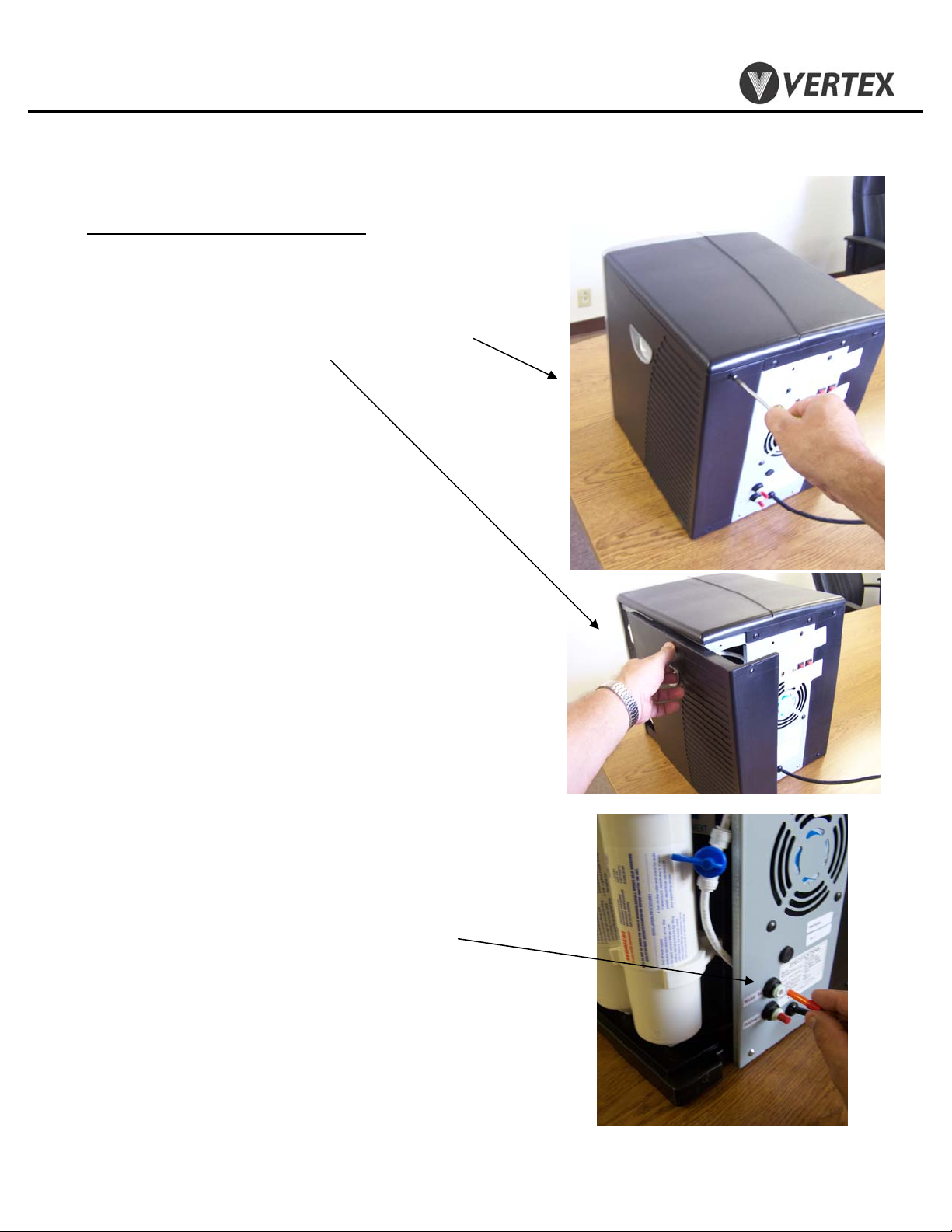
Feedwater/Drain Connections
-Feed Connection
2.1 Remove 2 screws on back of right side panel
and remove right side panel.
2.2 Remove feed water plug (orange) from back
of cooler.
Copyright 2008 Vertex Water Products
Page 5
PWC – 400
PureWaterCooler
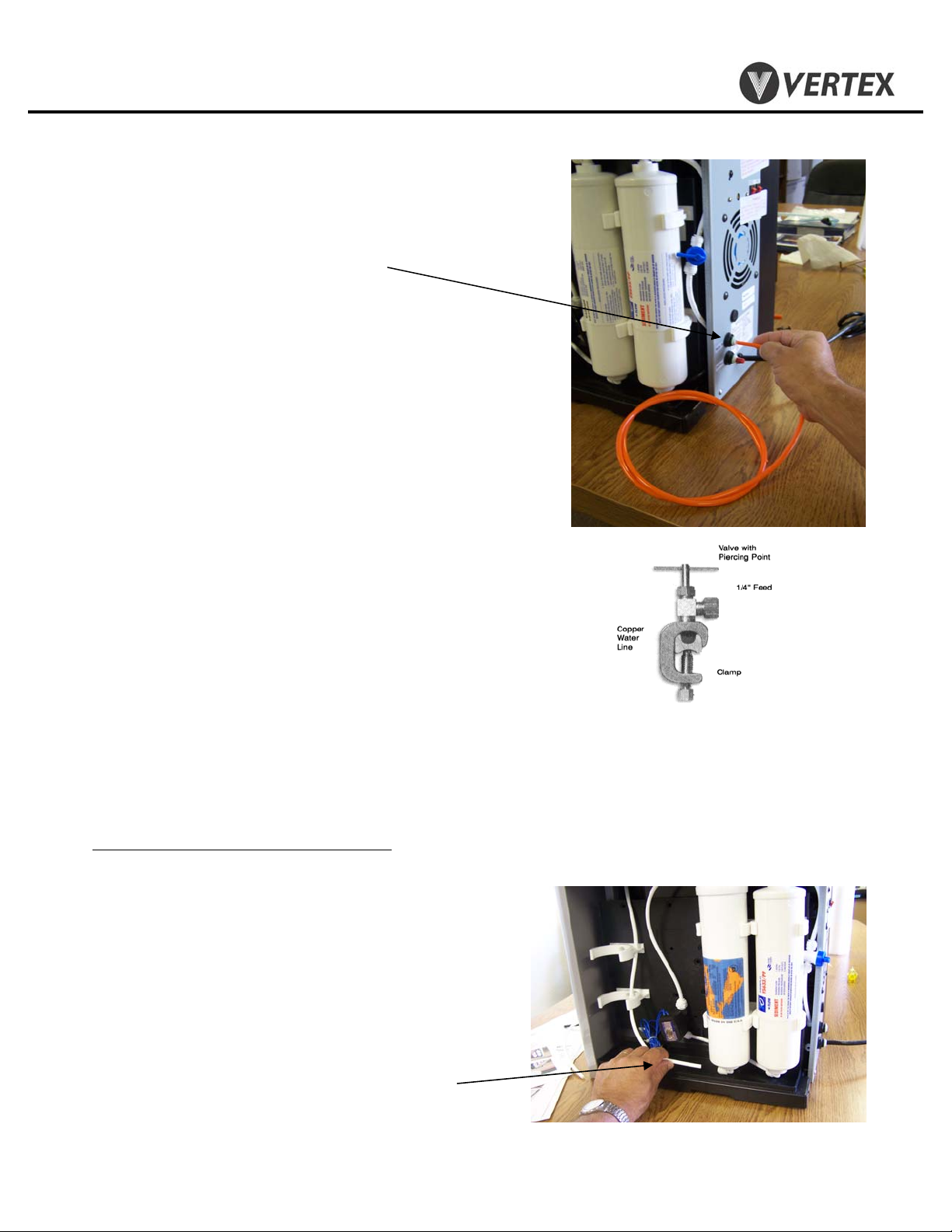
2. Cooler Set-Up cont.
2.3 Connect supplied orange feed water tubing to
feed connector on back of cooler.
2.4 Make feed water connection to cold water line.
A self piercing saddle valve is provided.
2.5 Flushing carbon fines from carbon filter
.
Most carbon filters have fine particles of
carbon material in the filter that will be
swept into the water stream when the first
water flows through the filter. Although not
harmful, these carbon fines in the water are
unsightly. Flush the carbon fines out of the
filter before filling cooler tanks with the
following procedure
2.6 Remove outlet line of carbon filter (bottom)
Feedwater connection (RO & filtration coolers
(For use on copper tubing)
Use supplied self piercing saddle valve.
Connect to water inlet on cooler u sing 1/4”
tubing. Clamp saddle valve over copper feed
water line (cold water line only). Tighten
needle valve until tube is pierced. Retract
needle 1 -2 turns to start water flow.
)
Copyright 2008 Vertex Water Products
Page 6
PWC – 400
PureWaterCooler
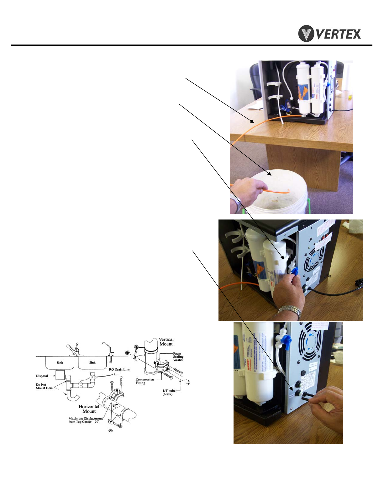
2. Cooler Set-Up cont.
2.7 Attach 3 feet of ¼” tubing to the carbon filter
outlet port (flush tubing)
2.8 Place flush tubing in bucket to catch water
carbon fines
2.9 Turn on feed water at source and turn ball valve
at filter to “on” to let the water flush the filter.
2.10 Flush until water flows clear (1 – 2 gallons)
2.11 Remove flush line. Reconnect tank line to
outlet of carbon filter
2.12 WARNING: Do not turn on cooler hot power
until cooler tanks are full of water.
Figure 2.7
Drain Connection (for units equipped with RO)
2.13 Remove drain plug (black) from back of cooler
2.14 Connect supplied black water tubing to
drain connector on back of cooler
2.15 Attach supplied drain saddle to a
standard 1 ½” drain pipe see fig. 1 below
Drain saddle connection method
Drain connection required only for cooler with reverse osmosis filtration
Figure 1
Copyright 2008 Vertex Water Products
Page 7
PWC – 400
PureWaterCooler
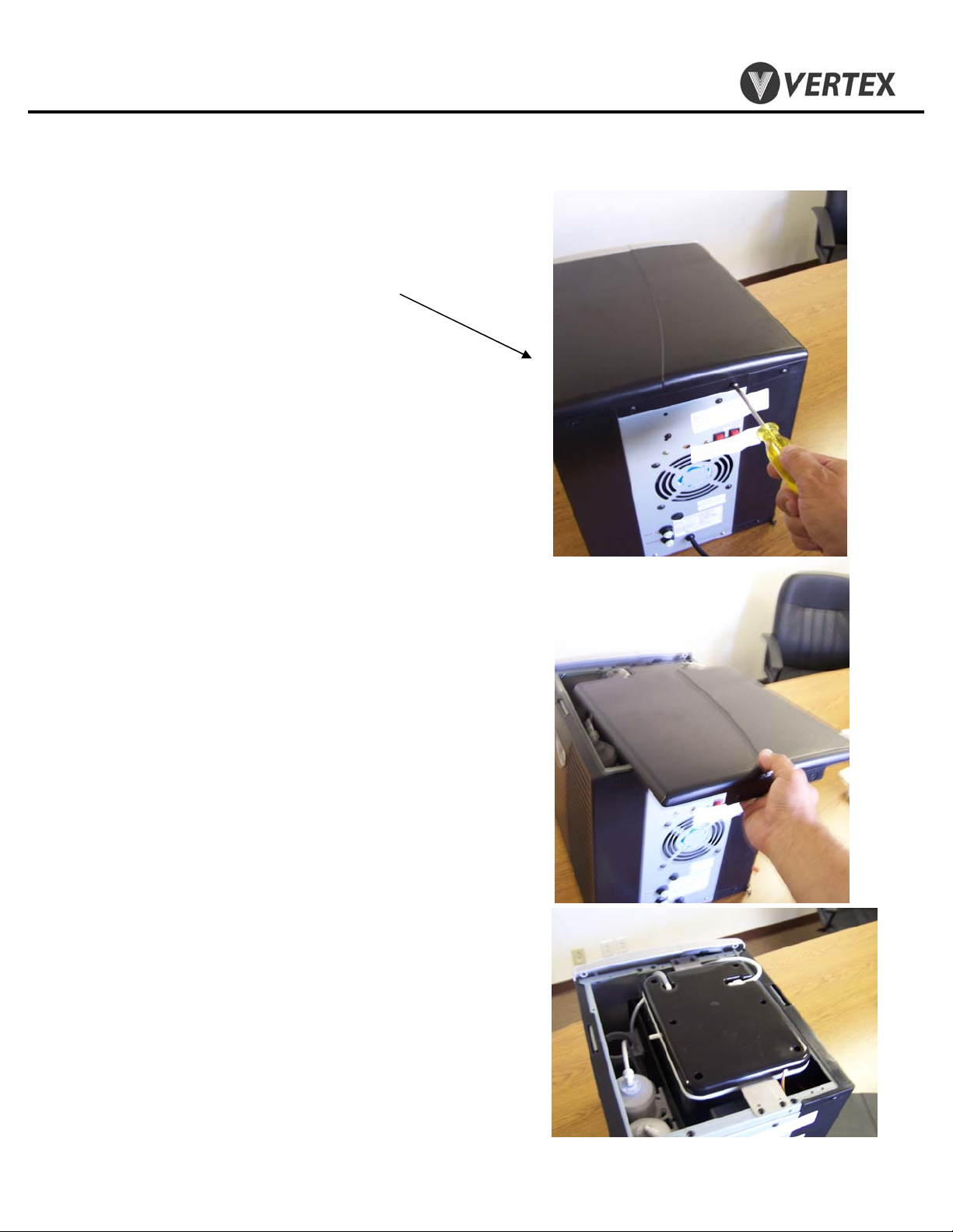
3. Top Cover/Side Panel Removal
3.1 Remove (2) screws on back of cooler top cover
3.2 Slide cover back and lift off.
3.3 Cold tank is now accessible for cleaning
and servicing other parts of the cooler.
3.4 Reinstall in reverse order
Copyright 2008 Vertex Water Products
Page 8
PWC – 400
PureWaterCooler
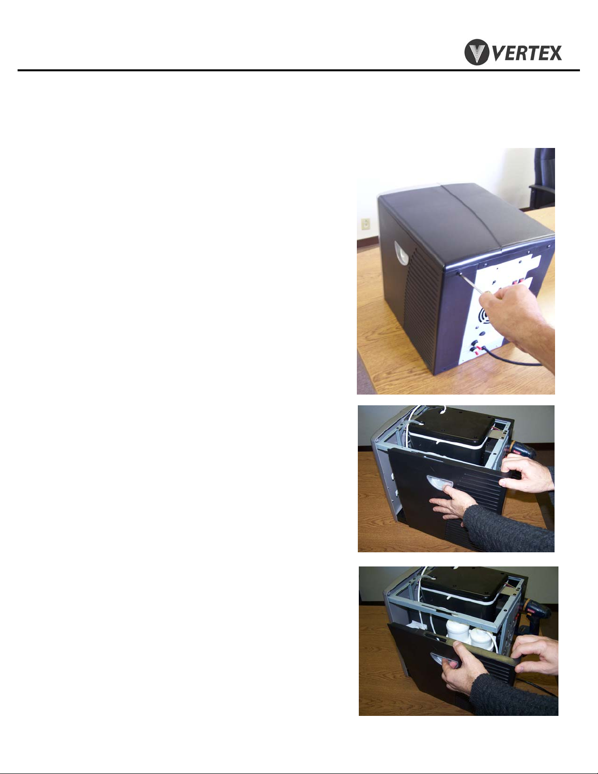
3. Top Cover/Side Panel Removal
3.5 Remove (2) screws on back of cooler side cover
Cont.
3.6 Slide side cover back about half way off until
tab in side cover lines up with slot in cooler
frame.
3.7 Once slot and tab are lined up, pull side cover
away from cooler.
3.8 Reinstall in reverse order
Copyright 2008 Vertex Water Products
Page 9
PWC – 400
PureWaterCooler
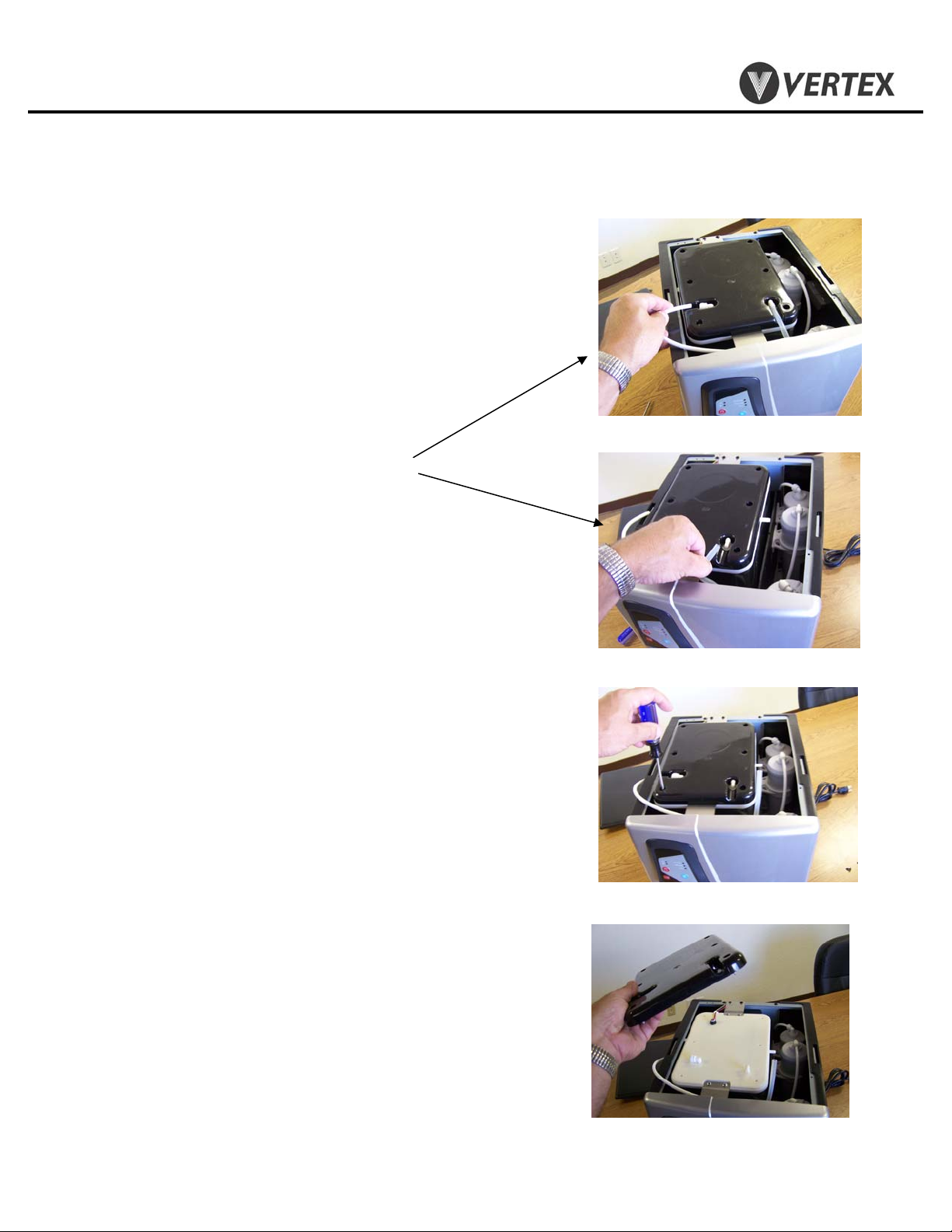
4. Remove/Replace Electro/Mechanical Float Assembly
4.1 Remove top cover (See section 3)
4.2 Remove tubing from top of cold tank
4.3 Remove screws from lid of cold tank. (6 plcs)
4.4 Remove outer lid of cold tank
Copyright 2008 Vertex Water Products
Page 10

PWC – 400
PureWaterCooler
4. Remove/Replace Electro/Mechanical Float Assembly
cont.
4.5 Disconnect electrical connector
4.6 Lift off inner lid of cold tank
4.7 To remove float, remove nut from float stem
4.8 Remove float assembly from inner lid.
4.9 Reinstall in reverse order.
Copyright 2008 Vertex Water Products
Page 11

PWC – 400
PureWaterCooler
5. Removing/Replacing Hot Tank.
5.0 Unplug power from wall
5.1 Drain water from cooler using front spigots
and by removing bottom drain plug.
5.2 Remove top cover and left and right side covers (sec. 3)
5.3 To gain access to the hot tank, the
filter bracket must be moved:
5.4 Remove water line from top of sediment filter
5.5 Put cooler on its’ left side
5.6 Remove 4 screws holding filter bracket to base
5.7 Set filter bracket aside to allow access to hot tank
Copyright 2008 Vertex Water Products
Page 12

PWC – 400
PureWaterCooler
5. Removing/Replacing Hot Tank
5.8 Remove wire from thermal sensors (4 places)
Cont.
5.9 Remove inlet tubing (Access from right side of
cooler)
5.10 Remove outlet tubing (Access from left side of
cooler)
Copyright 2008 Vertex Water Products
Page 13

PWC – 400
PureWaterCooler
5. Removing/Replacing Hot Tank
5.11 Remove vent tubing (top of hot tank)
Cont.
5.12 Remove the 2 screws that hold the tank from the
bottom of the cooler
5.13 Remove the hot tank from cooler
5.14 Remove (2) heating coil leads from hot tank
5.14 Remove Thermal sensors from hot tank. Save an
install on new hot tank.
5.16 Assemble hot tank in reverse order.
d
Copyright 2008 Vertex Water Products
Page 14

PWC – 400
PureWaterCooler
6. Dispensing Faucet Repair
6.1 Remove top and side covers of cooler (section 3)
6.2 Remove the control panel by grasping the bottom
of the panel and pulling out sharply.
6.3 Remove (4) electrical connectors from back of the
control panel. Set control panel aside.
Copyright 2008 Vertex Water Products
Page 15

PWC – 400
PureWaterCooler
6. Faucet Repair
Cont.
6.4 Remove hot water tubing from the left (hot) solenoid.
6.5 Remove screw holding solenoid/manifold assembly
to the front panel.
6.6 Remove solenoid/manifold assembly by lifting it
out of cooler. Disconnect cold water tubing from
cold water solenoid (right side).
Copyright 2008 Vertex Water Products
Page 16

PWC – 400
PureWaterCooler
6. Faucet Repair
6.7 Remove screw holding solenoid to manifold and
bracket. Slide solenoid off of manifold.
Cont.
6.8 Reassemble in reverse order.
Make note of the following:
a. Water flow through the solenoid is
directional. There is an arrow molded in
the side of the solenoid body showing
water flow direction. Make sure the solenoid
is oriented correctly. Water can leak from
the solenoid if not installed correctly
b. When installing electrical connectors into
the circuit board please note: the left
solenoids’ connector plugs into the left
socket on the circuit board (when you are
facing the circuit board). The right solenoid
plugs into the right
Copyright 2008 Vertex Water Products
Page 17

PWC – 400
PureWaterCooler
7. Remove/Replace Circuit Board
7.1 Remove dispensing control panel (section 6)
7.2 Remove circuit board cover
7.3 Remove (3) screws holding circuit board to panel
7.4 Re-assemble in reverse order
Copyright 2008 Vertex Water Products
Page 18

PWC – 400
PureWaterCooler
8. Remove Front Panel
8.1 Remove top and side covers of cooler (section 3)
8.2 Remove the control panel and dispensing solenoid
assembly (section 6.2)
8.3 Remove (2) screws from the top of the front panel. The
lower part of the front panel sets on two pins.
8.4 Lift front panel off of the two pins. Remove cover
8.5 Re-assemble in reverse order
Copyright 2008 Vertex Water Products
Page 19

PWC – 400
PureWaterCooler
9. Hot Tank Reset Button
9.0 To access the hot tank, remove the left side cover
per section 3.3
9.1 Observe that there are two circular sensors
attached to the hot tank. The upper one is the
main controller at 82 ºC and the lower sensor
is the over-temp cut off.
The power switch for the hot tank (at the back
of the cooler) should not be turned on until
water can be dispensed from the hot spigot. If
the hot power is turned on without water in the
hot tank the heating element will over heat. To
prevent this, the lower thermal sensor on the
hot tank will cut power to the heating element
before any damage takes place. If this happens
the switch on the thermal sensor can be reset to
operational mode manually by the following
procedure.
9.2 Make sure the power cord is unplugged.
9.3 Find the lower thermal sensor on the hot tank
9.4 Using a long thin object such as a screw driver
or a pen, depress the small button at the
center of the lower thermal switch. You should
feel a click when you depress the button. This
action resets the over-temp sensor.
Copyright 2008 Vertex Water Products
Page 20

PWC – 400
PureWaterCooler
10. Remove/Replace Thermal Sensor
10.0 The hot tank thermal sensors are located
on the outside of the hot tank. There are
two thermal sensors. The sensor located
higher on the hot tank controls the daily
operation of the heating element. The
lower thermal sensor is an overheat
safety switch and cuts power to the hot
tank should a malfunction occur and
the tank starts to overheat.
10.1 Unplug cooler from power source for
this operation.
10.2 Remove left side cover per sec. 3.3
10.4 There are (2) thermal sensors attached with
screws to the hot tank. The upper sensor automatically turns the heating element on and off
to maintain the water at 180 ºF. The lower
sensor is the over temperature sensor. This
sensor activates if the temperature on the tank
goes over 212 ºF. If this sensor is activated due
to a overheat condition, it will cut the power to
the heating element. If this happens, it can be
reset by pressing the button at the center of
the sensor.
To check if either thermal sensor is good, use a
continuity tester (ohm meter) to check for
continuity across the thermal sensor. Make
sure the thermal sensor is at ambient temperature
for this test. If there is no continuity, replace
the sensor.
10.5 To change either sensor, disconnect (2)
electrical terminals from sensor.
10.6 Remove (2) screws holding sensor to tank.
10.7 Install new thermal sensor, replace screws,
reconnect electrical terminals to sensor.
10.8 Replace left side cover.
Copyright 2008 Vertex Water Products
Page 21

PWC – 400
PureWaterCooler
11. Cold Tank Temperature Adjustment
11.0 The cold water temperature adjustment
is located on the back of the cooler in
the middle of the panel. An expansion
tube senses temperature in the cold
tank and open and closes the thermostat.
11.1 The cold adjustment is a shaft with a
screw driver slot on the end.
11.2 To make the water colder, using a
screw driver, rotate the shaft clockwise.
For warmer water rotate the shaft
counter clockwise. There are stops on
the adjustment shaft. DO NOT force
the control shaft over the stop. If this
happens, it will be necessary to replace
the temperature controller
270º Travel
STOP
WARMEST
COLDEST
STOP
Normal Travel is 270º
Copyright 2008 Vertex Water Products
Page 22

PWC – 400
PureWaterCooler
12. Sanitization Procedure
The sanitization procedure is performed to reduce/eliminate any bacteriological
growth in the cooler tanks and dispensing plumbing. Bacteriological growth
can be the cause of some taste and odor in the water.
The procedure is as follows:
1. Mix 1 teaspoon of common household bleach (5.25%) in 2 gallons of
clean water.
2. Unplug the cooler from the power source.
3. Drain all water from the cooler tanks.
4. Pour the sanitizing solution into the main (cold temperature) tank until full.
5. Open all spigots to allow sanitizing solution to fill the dispensing faucets.
Close the spigots.
6. Let the sanitizing solution stand in the cooler for 10 minutes.
CAUTION: Leaving the sanitizing solution in the cooler for more
than 10 minutes can cause taste problems in the water.
7. Completely drain the sanitizing solution from all the tanks per section 5
8. Fill the main (cold temp.) tank with clear tap water to rinse out the
sanitizing solution.
9. Completely empty the rinse water from the tanks.
10. The cooler is now sanitized and ready for filling with filtered water.
Copyright 2008 Vertex Water Products
Page 23

PWC – 400
PureWaterCooler
13. Trouble Shooting
Water not cold from cold tank
(Water dispenses from spigot but is not cold)
Possible causes Solution .
1. Cooler not plugged in Make sure power cord is plugged
into wall socket
2. Power switch not on Make sure cold power switch on
the back panel is on.
3. Adjust temperature control The thermostat temperature control
adjustment is located on the back
of the cooler. (see section 11)
4. All cold water has been drained Cooler needs time to recover.
wait 10-15 minutes until water cools
Copyright 2008 Vertex Water Products
Page 24

PWC – 400
PureWaterCooler
13. Trouble Shooting
Cont.
No Hot Water from Hot Tank
Possible Causes Solution
1. Cooler not plugged in Make sure power cord is plugged
into wall socket
2. Power switch not on Make sure Hot power switch on back
panel is on and hot power light on
front is illuminated
3. Electrical terminal Check to see that both wires are
disconnected connected to the heating element
terminals. These are located at the
bottom of the hot tank
4. Heating element failure Check for continuity across hot tank
due to scaling heater terminals. To do this, unplug
unit from wall power. Disconnect one
of the connector at the heating element
terminals (at bottom of tank). Using
an ohm meter, check for continuity
across the 2 terminals. If there is no
continuity (open), the tank must be
replaced.
Copyright 2008 Vertex Water Products
Page 25

PWC – 400
PureWaterCooler
13. Trouble Shooting Cont.
No Hot Water from Hot Tank cont.
Possible causes Solution .
5. Thermal sensor failure The thermal sensors are attached to the
hot tank. The upper sensor is a 96 ºC
sensor and functions as an over heat
safety. The lower sensor is a 82 ºC
sensor and controls the heating element
function. The lower sensor would be the
problem if there was no hot water. To
see if the sensor is functioning properly,
first unplug the cooler from the wall.
remove the terminal from the sensor.
Using an ohm meter, check for continuity
If there is no continuity (open), replace
sensor
as per section 10.
6. Hot tank turned on without The hot power should never be turned on
water in tank without water in the tank. If this happens,
the upper thermal sensor on the hot tank
will switch, cutting power to the hot tank.
This is a safety device to prevent the heating
element from burning itself out due to dry
heating. Once the hot tank cools off the
switch can be reset to operating condition.
See section 9.
Copyright 2008 Vertex Water Products
Page 26

PWC – 400
PureWaterCooler
13. Trouble Shooting Cont.
No Hot Water from Hot Tank cont.
An indicator of a hot tank problem can also be the lights on the front
control panel. Below is a table of trouble shooting help.
If the Hot Tank is not heating and the front panel lights are:
Front Panel Lights Cause Check
Hot Power – on Heating element disconnected No Continuity across
Heating - on or burned out heating element
No lights at all Lower thermal sensor Reset Press reset button /
Including cold power button disengaged or sensor No Continuity across
burned out thermal sensor –replace sensor
Hot Power – on Upper thermal sensor No Continuity across
Heating -- off disconnected or burned out lower thermal sensor
Copyright 2008 Vertex Water Products
Page 27

PWC – 400
PureWaterCooler
14. Specifications
PWC-400
Voltage/Frequency 120 VAC/ 60 Hz
Weight (dry) 48 lbs.
Total Water Capacity 1.5 gallons
Hot tank .5 gallons
Cold tank 1.0 gallons
Power Consumption Total 600 Watts
Hot Tank 500 Watts
Cold Tank 100 Watts
Temperature
Hot 180 ºF average
Cold (adjustable) 38 ºF average
Refrigerant R134a 36 mg.
Copyright 2008 Vertex Water Products
Page 28

4/09
Page 29

PWC-400 Part List
Item No. Description Part Number Item No. Description Part Number
P1 Top Cover cl4 9500 E1 Control Board, Rev C cl4 9529
P2 Front Panel cl4 9501 E1.1 Cntrl Brd w/beep snd, RevD,E cl4 9587
P3 Control Pnl/Fct Cover, Rev F cl4 9581 E1.2 Cntrl Brd w/beep snd, Rev F cl4 9580
P3 Cntrl Pnl/Fct Cover, Rev C,D cl4 9502 E2 Compressor cl1 9218
P4 Base cl4 9503 E3 Cold Temperature Switch cl4 9219
P5 Drip Tray Set cl4 9504 E4 Transformer cl4 9220
P6 Left Side Panel cl4 9505 E5 Power Cord cl4 9221
P7 Right Side Panel cl4 9506 E6 Control Box, Level Sensor cl4 9222
P8 Handle cl1 9235/EG E7 Fan cl4 9223
P9 Water Spout and T Manifold cl4 9508 E8 Condensor cl4 9224
P10 Cover, Circuit Board cl4 9509 E9 On/Off Switch cl1 9238
P10.1 Cover, Circt Brd, REV D,E,F cl4 9507 E10 Fuse Holder cl1 9252
P11 Strain Relief cl4 9510 E11 Fuse cl1 9262
P12 1/4" tubing cl4 9511 E12 Sol.Valve, Dspnsng,cold,24vd
E13 Wiring Harness cl4 9544
E14 Wire Harness cl4 9542
E15 Wire Harness cl4 9543
P16 Dispense Nozzle Cover cl4 9547 E16 Sol.Valve, Dspnsng,hot,24vdc cl4 9590
OBSOLETE REV E Control panel Assy cl4 9588
M1 Frame, Upper cl4 9512 REV F Control panel Assy cl4 9591
M2 Frame, Front cl4 9513
M3 Rear Panel cl4 9514 H1 Hot Tank cl4 9545
M4 Screw cl4 9515 H2 92 C Temperature sensor cl1 9277
M5 Screw cl4 9516 H3 82 C Temperature sensor cl2 9030
M6 Screen, Stainless 304 cl4 9528 H4 Screw cl4 9548
M7 Screw cl4 9517 H5 Screw cl4 9549
M8 Screw cl4 9518 H6 Stopper cl4 9555
M9 Bracket cl4 9519 H7 Insulating Foam cl4 9551
M10 Probe, Leak detector cl4 9520 H8 Silicon Tube cl4 9552
M11 H9 Silicon Tube, 175 x 4 elbow cl4 9553
M12 Screw cl4 9521 H10 Silicon Tube cl4 9554
M13 Dryer cl4 9522
M14 Screw cl4 9523
M15 Screw cl4 9524
M16 Screw cl4 9525
M17 Bracket cl4 9526
M18 Screw cl4 9527
M19
c cl4 9540
Vertex Water Products 2009
1 Rev F, 7/11
Page 30

PWC-400 Part List
Item No. Description Part Number Item No. Description Part Number
C1 Lid, Outer, Cold Tank cl4 9556 REV D, 7/09 1/4/2013
C2 Lid, Inner, Cold Tank cl4 9557 Updated 4/6/10
C3 Cold Tank Assembly cl4 9558 Updated 10/1/10
C4 Screw cl4 9559 Updated 12/31/10
C5 Silicon Tube cl4 9560 REV F, 7/11
C6 Level Sensor cl4 9579
C7 Capillary Tube cl4 9561
C8 Insulation cl4 9562
C9 Nut cl4 9578
C10 Fitting cl4 9563
C11 Insulation cl4 9564
C12 Insulation cl4 9565
C13 Insulation cl4 9566
C14 Bracket, Cold Tank cl4 9567
C15 Plug cl4 9568
C16 Screw cl4 9569
O1 Sticker, Cntrl Pnl, Rev C,D,E cl4 9573
O1 Sticker, Cntrl Pnl, Rev F cl4 9582
O2
O3 Double backed Tape cl4 9575
O4 Nut cl4 9576
O5 Solenoid Valve, 115 VAC cl2 9086
O6 Screw cl4 9570
O7 Filter Bracket cl4 9541
Fittng,Bulkhead
(nt usd aftr 8.09)
cl4 9574
Sediment Filter Cart.-rplcmnt ifa 4035
Carbon Filter Cart.-rplcment ifa 4034
Membrane, 50 gpd-rplcmnt ma 4203
UV bulb, 6 watt - rplcment uv 4061
O52 Straight, 1/4mpt x 1/4 tube md 2624
O53 Elbow, 1/4 mpt x 1/4 tube md 2625
O54 Bulkhead fitting, 1/4" dm 2733
O55 Stem Elbow, 1/4stem x 1/4t md 2626
O56 Filter Screen, 1/4"
Vertex Water Products 2009
2 Rev F, 7/11
 Loading...