

Vertex FTL-1011, FTL-2011, FTL-7011 Operating Manual
"
FM Land Mobile Transceivers
'Operating Manual
YAESU MUSEN CO.,
Ltd.
CP.0.
Box
1500, Tokyo, Japan
YAESU U.S.A.
17210 Edwards Rd., Cerritos, CA 90701, U.S.A.
YAESU EUROPE
B.V.
Snipweg 3,1118AA Schiphol, The Netherlands
Congratulations!
You now have at your fingertips a valuable communications
tool
-
a Yaesu two-way radio! Rugged, reliable and easy to use,
i
your Yaesu radio will keep you in constant touch with your
I
colleagues for years to come, with negligible maintenance
down time.
Please take a few minutes to read this manual carefully. The
information presented here will allow you to derive maximum
performance from your radio. After reading it, keep the manual
handy for quick reference, in case questions arise later on.
We're glad you joined the Yaesu team. Call on us any time,
because our business is communications. Let us help you get
your message across.
NOTICE
There are no user-servicable points inside this transceiver. All service jobs must be referred to your Authorized
Service Center or Network Administrator.
FTH-1011, FTL-2011 VHF
and FTL-7011 UHF
FM Land Mobile Transceivers
The 60-watt VHF Low-Band FTL-1011, 40-watt VHF HighBand FTL-2011 and 25-watt UHF FTL-7011 are rugged, full-featured FM transceivers designed for flexible mobile and base
station business communications. Each model is available with
either a
-4
or -12 suffix, with a capacity of either 4 or 12 channels,
respectively
.
Reliability is assured by a highly integrated surface mount
circuit design and a die-cast aluminum chassis. Important channel frequency data is stored in EEPROM, and is easily programmable by dealers using a personal computer and the Yaesu
FRB-2 Interface Box,
T9101410 Cable and CE-5 or VPL-1 Soft-
ware.
Special features include a built-in CTCSS (Continuous Tone
Coded Squelch System) and in the 12-channel versions, two
sets of scanning channels, one set preselectable by the dealer
and another operator selectable. The operator can select which
set to scan, and also two priority channels. Dealers can program
Busy Channel Lockout, transmitter time out timers and scan
stop activities for
talkback on the paused channel, priority
channel or the home channel (on which scanning was initiated).
Scanning is not provided in the 4-channel versions.
Each transceiver is supplied with a mobile bracket and hand
microphone. Options include the FP-711 Power Supply for operation from the AC mains, the FDS-1 Digitally Coded Squelch
Unit and F2D-4 2-Tone Decoder programmable by your dealer.
Please take a few minutes to read this manual carefully. The
information presented will help you derive maximum performance from the equipment. After reading, keep it handy near the
radio for quick reference.
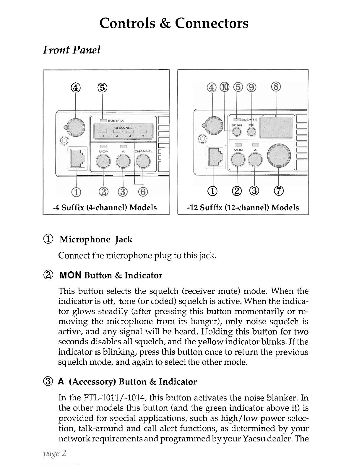
Controls
&
Connectors
Front
Panel
--
@
0
C
--
--
-
-4
Suffix
(Cchannel) Models
0
00 0
-12
Suffix
(12-channel) Models
@
Microphone Jack
Connect the microphone plug to this jack.
@
MON
Button & Indicator
This button selects the squelch (receiver mute) mode. When the
indicator is off, tone (or coded) squelch is active. When the indicator glows steadily (after pressing this button momentarily or removing the microphone from its hanger), only noise squelch is
active, and any signal will be heard. Holding this button for two
seconds disables all squelch, and the yellow indicator blinks. If the
indicator is blinking, press this button once to return the previous
squelch mode, and again to select the other mode.
@
A
(Accessory) Button & Indicator
In the FTL-loll/-1014, this button activates the noise blanker. In
the other models this button (and the green indicator above it) is
provided for special applications, such as
high/low power selection, talk-around and call alert functions, as determined by your
network requirements and programmed by your Yaesu dealer. The
Vertex
FTL-1011, FTL-2011 & FTL-7011
Operating Manual
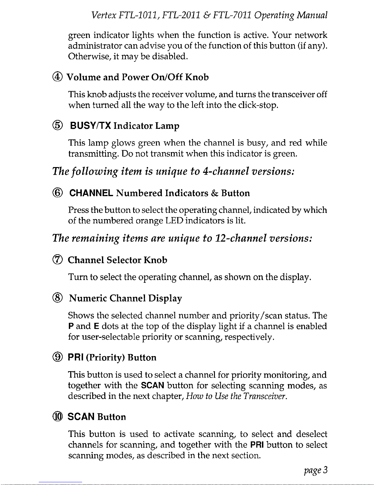
green indicator lights when the function is active. Your network
administrator can advise you of the function of this button (if any).
Otherwise, it may be disabled.
@
Volume and Power
OnfOff
Knob
This knob adjusts the receiver volume, and turns the transceiver off
when turned all the way to the left into the click-stop.
@
BUSYITX
Indicator Lamp
This lamp glows green when the channel is busy, and red while
transmitting. Do not transmit when this indicator is green.
The following item is unique to 4-channel versions:
@
CHANNEL
Numbered Indicators
&
Button
Press the button to select the operating channel, indicated by which
of the numbered orange LED indicators is lit.
The remaining items are unique to 12-channel versions:
@
Channel Selector Knob
Turn to select the operating channel, as shown on the display.
@
Numeric Channel Display
Shows the selected channel number and priority/scan status. The
P
and E dots at the top of the display light
if
a channel is enabled
for user-selectable priority or scanning, respectively.
@
PRI
(Priority) Button
This button is used to select a channel for priority monitoring, and
together with the
SCAN
button for selecting scanning modes, as
described in the next chapter,
How to Use the Transceiver.
@
SCAN
Button
This button is used to activate scanning, to select and deselect
channels for scanning, and together with the
PRI
button to select
scanning modes, as described in the next section.
Page
3

Vertex
FTL-1011, FTL-2011
6
FTL-7011
Opevati/?g
Mnnual
REAR
(Heatsink)
@
13.6VDC Cable Pigtail wlconnector
The
supplied
DC
power cable must be connected to .this 2-pin
connector. Use only the supplied fused cable, extended if necessary, for power connection.
@
Antenna Socket
The 50-ohm coaxial feedline to the antenna must be connected here
using a type-M (PL-259) plug.
@
EXT
SP
(External Speaker)
External loudspeakers may be connected to this 2-contact, 3.5-mm
mini-phone jack.
 Loading...