

Page 1
1.Introduction
1.1.Highlight Features
■ Space saving, only 55mm panel depth required
■ Higher sampling rate (100mS) results in better control performance
■ Protect the load from thermal shock (unwanted rapid temperature rise) using the excellent ramp
rate feature
■ Protect the heating element from excess current during power-up using the soft start function
■ Easy to read 0.4” / 10mm LED display showing SV/PV at a glance
■ NEMA-4 IP65 front panel protection when used with panel gasket or IP63 without
1.2.Specification
Input signal : User programmable. refer to table 1.
■ Thermocouple (T/C) : industry standard thermocouple types, J, K, T, E, B, R, S, N, C (ITS-90).
■ Pt100 : Excitation 180uA. 2 or 3 wire connection (ITS-90 α=0.00385).
■ Voltage : -60mVdc to 60mVdc or -10Vdc to 10Vdc.
■ Current : 0mA to 24mA
Measuring range : User programmable. Maximum range refer to table 1.
Measuring accuracy : refer to Table 1. the accuracy is tested under the operating condition of
24°C±3°C.
*Factory Setting
Note 1 : Accuracy is not guaranteed between 0 and 400°C (0 and 752°F) for type B.
Table 1 Input Signal
Sampling rate : 100mS
Control Output :
■ Relay output : 5A/240Vac (Resistive load)
■ Pulsed Voltage output : DC 0/24V (Resistive load 1.2K ohms Min.)
■ Current output : 4~20mA (Resistive load 600 ohms Max.)
■ Voltage output : 0~10V ( Resistive load 600 ohms Min.)
Control Mode : PID with auto-tune, P with manual reset or On/Off with hysteresis available.
■ Proportional Band : 0.0~300.0% (0.0 % = On/Off mode)
■ Integral Time : 0.0~3000 sec.
■ Derivative Time : 0.0~1000 sec.
■ Cycle Time : 0~60 sec.
■ Hysteresis : 0~9999
Ramp Function :
■ Ramp rate : 0~9999 unit/minute or unit/second (0 = disable the ramp function)
Accuracy
±1°C
±1°C
±1°C
±1°C
±2°C
(Note1)
±2°C
±2°C
±2°C
±2°C
±0.2°C
±0.2°C
±4μA
±0.01mV
±2mV
Maximum Range
-50 to 1000°C (-58 to 1832°F)
-50 to 1370°C (-58 to 2498°F)
-270 to 400°C (-454 to 752°F)
-50 to 750°C (-58 to 1382°F)
0 to 1800°C (32 to 3272°F)
-50 to 1750°C (-58 to 3182°F)
-50 to 1750°C (-58 to 3182°F)
-50 to 1300°C (-58 to 2372°F)
-50 to 1800°C (-58 to 3272°F)
-200 to 850°C (-328 to 1562°F)
-200 to 600°C (-328 to 1112°F)
-24mA~24mA
-60mV~60mV
-10V~10V
Input signal
Thermocouple J
Thermocouple K*
Thermocouple T
Thermocouple E
Thermocouple B
Thermocouple R
Thermocouple S
Thermocouple N
Thermocouple C
Pt100 (DIN)
Pt100 (JIS)
mA
mV
Voltage
F4 Process Controller
Installation and Operation Guide
Alarm Output : 5A/240Vac (Resistive load)
Alarm Function : Energized / De-energized with 0~30000 Sec. / Min. delay
■ No alarm
■ Process high alarm
■ Process low alarm
■ Deviation high alarm
■ Deviation low alarm
■ Inside deviation band alarm
■ Outside deviation band alarm
Alarm Mode :
■ Normal mode
■ Standby mode
■ Latch mode
■ Standby and Latch mode
Communication :
■ Interface : Half duplex based on EIA RS-485
■ Protocol : ModBus RTU mode
■ Data format :
Start bit : 1
Data bit : 8
Parity : None
Stop bit : 2
■ Baud Rate : 2400, 4800, 9600, 19200 bps
Power supply : 100~240 Vac, 50/60 Hz / 24Vdc
Power consumption : 4VA Max.
Common mode rejection ratio : >80dB.
Operating temperature : 0 to 50°C
Humidity : 0 to 85% RH (Non-Condensing)
Electromagnetic compatibility (EMC) : En 50081-2, En 50082-2
Dimension : 48x48x55 mm (WxHxD).
Housing material : ABS plastic. UL 94V0
Weight : 100g
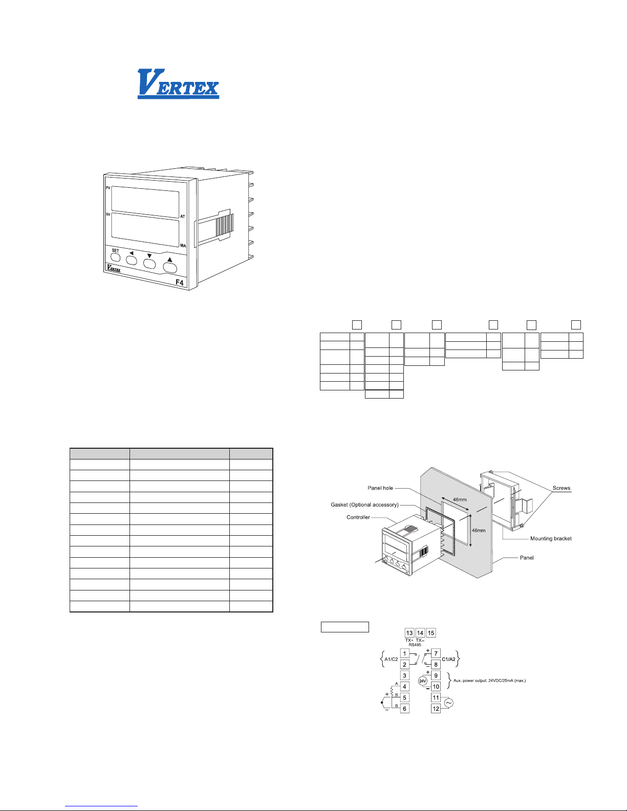
1.3.Ordering information
2.Installation
2.1.Panel mounting
1.Prepare the panel cutout with proper dimensions (45.5 X 45.5 mm)
2.Insert the controller into the panel cutout from the front of the panel.
3.Secure the controller by pushing the mounting bracket into the controller from the rear side.
4.Tighten the screws of the mounting bracket slightly if the controller is not firmly secured
Figure 1. Panel mounting
2.2.Connections and wiring
AC power supply
-0.0
+0.5
-0.0
+0.5
Input
T/C
PT100
(RTD)
0-60mV DC
0-10V DC
0-24mA DC
Code
T
D
L
V
M
Output 1
(Alarm2)
Relay
SSR
4~20mA
0-10V
Other
Alarm 2
Code
R
P
M
V
O
A
Alarm 1
(Output2)
Alarm 1
Relay
Code
A
R
Communication
None
RS-485
Code
N
C
Power
Supply
100~240
Vac
24 Vdc
Code
A
D
Protection
IP 63
IP 65
Code
3
6
F4
Control output 1 (can be converted to 2nd Alarm)
Relay output : 5A/240Vac (Resistive load)
Pulsed Voltage output : DC 0/24V (Resistive load 1.2K ohms Min.)
Current output : 4~20mA (Resistive load 600 ohms Max.)
Voltage output : 0~10V ( Resistive load 600 ohms Min.)
Relay output :
5A/240Vac (Resistive load)
Power supply : 100~240 Vac, 50/60 Hz
Alarm 1 output
(can be converted to 2nd output)
Page 2
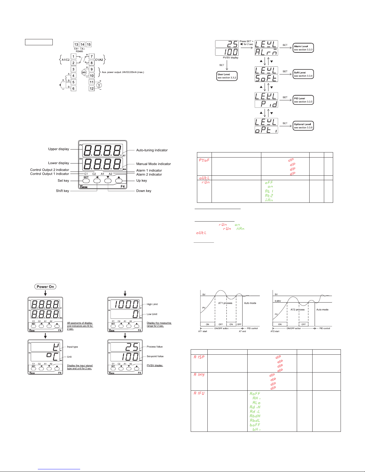
Figure 5. Menu flowchart
3.3.2.User Level
Process value offset correction
The value to be added to the PV to correct the sensor offset error.
Control output percentage
In Auto mode ( = ), it shows the percentage of power applied to the control output.
In Manual mode ( = ), the upper display will show the process value (PV) and
“ ” alternately and the “MA” indicator is lit. The value of percentage can be changed manually.
Control mode
Select the control mode to be
Off – Standby mode. Both control output and alarm are turned off.
On – Auto mode (closed loop control). In this mode, the control output percentage is determined
by PID algorithm or ON/OFF action.
AT1 – Auto-tuning mode 1. In this mode, the controller will tune the PID parameters automatically
at SV. The process will oscillate around the SV during AT1 process (Figure 6). Use AT2
mode if overshooting beyond the normal process is likely to cause damage.
AT2 – Auto-tuning mode 2. In this mode, the controller will tune the PID parameters automatically
at (SV-10%). The process will oscillate around (SV-10%) during AT2 process (Figure 6).
Man – Manual mode (open loop control). In this mode, the control output can be set manually.
Figure 6. Auto-tuning Process
3.3.3.Alarm Level
Display Description
Alarm 1 set-point
Alarm 1 hysteresis
Alarm 1 function
Range
-1999~9999 ( =0000)
-199.9~999.9 ( =000.0)
-19.99~99.99 ( =00.00)
-1.999~9.999 ( =0.000)
0~9999 ( =0000)
0~999.9 ( =000.0)
0~99.99 ( =00.00)
0~9.999 ( =0.000)
Default
10
0
Unit
unit
unit
DC power supply
Figure 2. Terminal connections
Wiring precaution:
Inverter, mechanical contact relays, arc welders, and ignition transformers are all common sources
of electrical noise in an industrial environment, so always keep signal wires away from those
noise-generating devices.
3.Operation
3.1.Front panel description
Figure 3. Front panel description
■ PV ( Upper display ) : Display the process Value, parameter index code or error code
■ SV ( Lower display ) : Display the set point value or the set value of parameter
■ C1 : Control output 1 indicator
■ C2 : Control output 2 indicator
■ A1 : Alarm 1 indicator
■ A2 : Alarm 2 indicator
■ AT : Auto-tuning indicator (The right-most decimal point of upper display)
■ MA : Manual mode indicator (The right-most decimal point of lower display)
Keypad description
■ SET key : Use to menus navigation and set value registration
■ Shift key : Shift the digit of numeral
■ Down key : Decreases the parameter value or change the setting
■ Up key : Increases the parameter value or change the setting
■ SET + Shift key for 2 sec. : Enter set up mode
■ SET + up key : Return to PV/SV display
■ Shift + Down key on powering up : set all parameters to default setting
3.2.Powering up procedure
Figure 4. Powering up procedure
3.3.Configuration
3.3.1.Menu Flowchart
After powering up procedure, the controller stays in PV/SV display. The upper display shows the
process value (measuring value) and the lower display shows the set point value (target value). All
the configurable parameters are located in different levels and can be accessed by keypad
operation as shown in figure 5.
Display Description
Process value offset correction
Control output percentage
Control mode
Range
-1000~1000 ( =0000)
-100.0~100.0 ( =000.0)
-10.00~10.00 ( =00.00)
-1.000~1.000 ( =0.000)
0.0~100.0%
: Off
: On
: AT1
: AT2
: Man
Default
0
N/A
On
Unit
Unit
%
N/A
Control output 1 (can be converted to 2nd Alarm)
Relay output : 5A/240Vac (Resistive load)
Pulsed Voltage output : DC 0/24V (Resistive load 1.2K ohms Min.)
Current output : 4~20mA (Resistive load 600 ohms Max.)
Voltage output : 0~10V ( Resistive load 600 ohms Min.)
Relay output :
5A/240Vac (Resistive load)
Alarm 1 output
(can be converted to 2nd output)
DC24V
: A.oFF
: A.Hi
: A.Lo
: A.diH
: A.diL
: A.bdH
: A.bdL
: b.oFF
: b.Hi
A.diH N/A
Page 3

*All the alarm 2 parameters are only shown when the control output is set as 2nd alarm action.
Alarm 1 set-point, Alarm 2 set-point
The set point of alarm even
Alarm 1 hysteresis, Alarm 2 hysteresis
The hysteresis of alarm action
Alarm 1 function, Alarm 2 function
Select the alarm function
A.oFF – Alarm action off.
A.Hi – Process high alarm with Form A contact
A.Lo – Process low alarm with Form A contact
A.diH – Deviation high alarm with Form A contact
A.diL – Deviation low alarm with Form A contact
A.bdH – Deviation band high alarm with Form A contact
A.bdL – Deviation band low alarm with Form A contact
b.oFF – Alarm action off
b.Hi – Process high alarm with Form B contact
b.Lo – Process low alarm with Form B contact
b.diH – Deviation high alarm with Form B contact
b.diL – Deviation low alarm with Form B contact
b.bdH – Deviation band high alarm with Form B contact
b.bdL – Deviation band low alarm with Form B contact
Figure 7. Alarm function
Alarm 1 mode, Alarm 2 mode
Select the alarm mode as
None – Disable the alarm mode
Stdy – Standby mode. When selected, prevents an
alarm on power up. The alarm is active after
alarm condition has been cleared and then
alarm occurs again.
LAtH – Latch mode. When selected, the alarm output
and indicator latch as the alarm occurs. The
alarm output and indicator will not change its
state even if the alarm condition has been
cleared unless the power is off.
StLA – Both standby and Latch mode are applied.
Figutr 8 shows the result of different alarm modes
applied on Deviation Band High Alarm with alarm
hysteresis set to 0.
Alarm 1 delay time, Alarm 2 delay time
Alarm delay time is set to postpone the alarm action
by the setting time. Figure 8. Alarm Mode
3.3.4.Soft Level
: b.Lo
: b.diH
: b.diL
: b.bdH
: b.bdL
: None
: Stdy
: LAtH
: StLA
oFF, 00.01~99.59
Same as Alarm1 set-point
Same as Alarm1 set hysteresis
Same as Alarm1 function
Same as Alarm1 mode
Same as Alarm1 delay time
Alarm 1 mode
Alarm 1 delay time
Alarm 2 set-point*
Alarm 2 set hysteresis*
Alarm 2 function
Alarm 2 mode*
Alarm 2 delay time*
None
oFF
10
0
A.diL
None
oFF
N/A
HH.MM/MM.SS
Unit
Unit
N/A
N/A
HH.MM/MM.SS
Description
Ramp rate
Soft start time
Range
oFF, 1~9999 (0.1~999.9)
oFF, 00.01~99.59
Default
oFF
oFF
Unit
Unit / sec.(min)
Minutes : Seconds
Display
Cut-off function
: None
: Low
: High
: High/Low
None N/A
Description
Input signal type
Range
: J type
: K type
: T type
: E type
: B type
: R type
Default
K type
Unit
N/A
Display
Description
Proportional band
Integral time
Derivative time
Manual reset
Anti-reset windup
Hysteresis for ON/Off control
Cycle time
Cooling proportional band
Dead band
Cooling cycle time
Range
0.0~300.0
oFF,1~3000
oFF,1~1000
0.0~51.0
0.0~100.0
0~1000 (0.0~100.0)
0~60
0.0~300.0
-1000~1000(-100.0~100.0)
1~60
Default
5.0
240
60
0.0
50.0
0
15
5
0
15
Unit
%
Sec.
Sec.
%
%
uint
Sec.
%
°C, °F or Engineering Unit
Sec.
Display
Ramp rate
The controller can act as either a fixed set point
controller or as a single ramp controller. If the ramp
rate is set to a value other than “oFF”, the process
will increase or decrease at the setting rate during
initial power up or with set point change. The ramp
rate is in degree per min. or sec. depends on the
time scale set in PTME.
Figure 9. Ramp Function
Soft start time
Soft start time can be programmed in situation where
100% output is not allowed at power up. The time
duration for the output to rise from 0% to 100% is
defined as soft start time.
Figure 10. Soft Start
3.3.5.PID Level
Proportional band
Set the proportional band in percentage of SPAN (High limit - Low limit). It can be set automatically
by auto-tuning process.
Integral time
Set the integral time constant in repetitions per second. It can be set automatically by auto-tuning
process.
Derivative time
Set the derivative time constant in second. It can be set automatically by auto-tuning process.
Manual reset
For PID control, this value is set automatically after auto-tuning process. For P control, it is used to
compensate the deviation between process value and set point.
Anti-reset windup
The anti-reset windup (ARW) inhibits the integral action
until the process value is within the band thus reducing
overshoot on start-up. The ARW can be set
automatically by auto-tuning process and then can be
changed manually if required
Hysteresis for ON/OFF control
In ON/OFF control (Proportional band set to 0.0%), the
control output turns On/Off with respect to the set point.
Therefore, the control output would change frequently in
response to a slight change in process value. This might
shorten the service life of the output device. To prevent Figure 11. ON/OFF Control Action
this, a hysteresis is provided in the ON/OFF control.
Cycle time
Set the control output cycle time. It is recommended to set to 15 sec. for Relay output and set to
1 sec. for pulsed voltage output.
Cooling proportional band
Set the cooling proportional band in percentage of SPAN (High limit – Low limit). It can be set
automatically by auto-tuning process. Set to 0.0 for ON/OFF control mode.
Dead band
This setting defines the area in which both heating and cooling outputs are inactive, known as dead
band, or the area in which they are both active, known as overlap. A positive value results in a dead
band, while a negative value results in an overlap.
Cooling cycle time
Set the cooling output cycle time. It is recommended to set to 15 sec. for Relay output.
3.3.6.Option Level
Low scale for linear input
High scale for linear input
: S type
: N type
: C type
: PT100 (DIN)
: PT100 (JIS)
: mA
: mV
: V
-1999~9999
-1999~9999
0
1000
Unit
Unit
Page 4

Error protection
0000
0001
0010
0011
A1 / C2
OFF
OFF
ON
ON
C1 / A2
OFF
ON
OFF
ON
Unit
Decimal point
Control action
Low limit
High limit
Digit filter
Time scale
Error protection
Security lock
Setpoint offset
Communication ID
Baud rate
: °C
: °F
: Engineer
0000
000.0
00.00 (for linear input signal only)
0.000 (for linear input signal only)
: Dir
: Rev
Refer to table 1.
Refer to table 1.
0.0~99.9
: HH.MM
: MM.SS
0000
0001
0010
0011
0000
0001
0010
0011
0100
0101
0110
-1999~9999 (
=0000)
-199.9~999.9 (
=000.0)
-19.99~99.99 (
=00.00)
-1.999~9.999 (
=0.000)
1~247
: 2.4K
: 4.8K
: 9.6K
:19.2K
°C
0000
Rev
0
1000
0.0
HH.MM
0000
0110
0
247
19.2K
N/A
N/A
N/A
Unit
Unit
Sec.
N/A
N/A
N/A
Unit
N/A
bps
Thermocouple
RTD
0~24 mA
-60~60 mV
-10~10 V
G1
Linked
Open
X
X
X
GA1
Linked
Linked
Linked
Linked
Open
GB1
Open
Open
Open
Open
Linked
GY
Open
Open
Linked
Open
Open
Input signal type
Select the input signal type. The available input signal types are :
Thermocouple : J K T E B R S N C
RTD : PT100 (JIS standard) or PT100 (DIN standard)
Linear : 0~24mA, -60~60 mV or 0~10 V
Please note that the internal gaps on the main board of F4 controller should be configured in
accordance with input signal.
X : don’t care
Figure 12. Gaps Allocation
Low scale for linear input
Select the low scale corresponding to low linear input signal. The default low linear input signal
(INL) for mA, mV and V is 4.00mA, 0.00mV and 0.00V separately. This parameter is only showed
when the input signal type is set to linear. (See also the cut-off function for further detail)
High scale for linear input
Select the high scale corresponding to high linear input
signal. The default low linear input signal (INH) for mA,
mV and V is 20.00mA, 50.00mV and 10.00V separately.
This parameter is only showed when the input signal
type is set to linear. (See also the cut-off function for
further detail)
Cut-off function
The Cut-off function is used to limit the process value of
linear input signal within the boundary whenever the
input signal is out of the high/low limit range (set by Hilt
and LoLt). The cut-off function can be set to “Low”,
“High” or “High/Low”, set to “None” disables the cut-off
function. The cut-off function has no effect for input
signal other than linear input. Figure 13. Scale and Cut-off Function
Only the security lock is open to change, all other parameters are locked
Only the security lock and set point value is changeable. all the other
parameters are locked
The user level is open to change.
The user and alarm levels are open to change.
The user, alarm, and soft levels are open to change.
The user, alarm soft and PID levels are open to change.
All parameters are open to change.
Security lock
0000
0001
0010
0011
0100
0101
0110
Range: 0 ~ 3
Unit: N/A
PV scale calculation:
Where
IN: the linear input signal.
INH: the high calibration of linear input signal. It is set in calibration parameters (mAL, mVL and VL).
INL: the low calibration of linear input signal. It is set in calibration parameters (mAH, mVH and VH).
Example:
For a 4~20mA input signal, the INL is set by mAL=4.00mA and the INH is set by mAH=20.00mA.
Set SCAL=0.0 SCAH=100.0 (Of course, you may select other scale value and decimal point to
alter the resolution) and LoLt=0.0 HiLt=100.0.
For a 12mA input, the PV will be 50.0.
For a 22mA input, the PV will be 112.5 with cut-off function set to “None” or 100.0 with cut-off
function set to “High” or “High/Low”.
For a 0mA input, the PV will be -25.0 with cut-off function set to “None” or 0.0 with cut-off function
set to “Low” or “High/Low”.
Unit
Select the process value indication in °C or °F when the input signal type is set to thermocouple or
PT100. Select engineer unit for linear input (mA, mV or V).
Decimal point
Select the decimal point position. The setting 00.00 and 0.000 is available for linear input only.
Control action
Dir – Direct action used for cooling process
Rev – Reverse action used for heating process
Low limit
Set the low limit of measuring range. When the PV goes below the low limit, the PV display flashing
indicates a low limit error. The control output and alarm will be set according to the Error Protection.
High limit
Set the high limit of measuring range. When the PV goes beyond the high limit, the PV display
flashing indicates a high limit error. The control output and alarm will be set according to the Error
Protection.
Digit filter
Set the time constant for digit filter (the first order filter). It is useful when the process value is too
unstable to be read.
Figure 14. Digit Filter
Time scale
Set the time scale used for alarm delay time and ramp rate.
HH.MM – The alarm delay time is in hour and minute / The ramp rate is in per minute.
MM.SS – The alarm delay time is in minute and second / The ramp rate is in per second.
Error protection
Set the control output and alarm status whenever an error occurred. (refer to 4 Error Message)
Security lock
The security lock is useful to lock out the parameters from unauthorized changed
Set point offset
Shift the set point value with an offset. The actual control target is shifted with this offset from set
point value but not added to SV display.
Communication ID
Set the ID number in the communication network
Baud rate
Set the communication baud rate.
( )
SCALSCALSCAH
INLINH
INLIN
PV +−
−
−
=
Page 5

Display
Flashing
Error Description
Sensor break or open
Input signal has out of A/D
converter range
The content of EEPROM is
corrupt
Fail to complete the auto-tuning
process within 2 hours
The PV is out of range
Correction
1. Check the sensor is connected and input signal
type is selected correctly.
2. Replace the sensor
1. Check the sensor is connected and input signal
type is selected correctly.
2. Replace the sensor.
3. Return to the supplier for repairing
1. Return to default setting by pressing shift and
down keys simultaneously while power on. And
reconfigure the parameters
2. Return to the supplier for repairing
1. Retry the auto-tuning again.
2. Improve the control process to have fast response
or use manual tuning instead of auto-tuning
1. Check the sensor is connected and input signal
type is selected correctly
2. Check the polarity of sensor is connected correctly
3. Check the high/low limit is set properly.
4. Replace the sensor
4.Error Message
 Loading...