

Page 1

C-RING TOOL VA0278
Rev H 4-30-2010
OPERATING MANUAL
1798 Sherwin Avenue
Des Plaines, IL 60018 U.S.A.
EMAIL: vertex@leggett.com
PHONE: 847-768-6139 FAX: 847-768-7192
Page 2

Operational Instructions for Vertex C-Ring Tool VA0278
Rev H 4-30-2010
Vertex Fasteners is committed to providing our customers with world-class customer
service and support. Our dedicated regional sales/service technicians are Vertex employees.
They know the product, the business, and their customers, and are there to serve you. Vertex
also has a well-trained staff of customer service, production and engineering professionals that
are ready and able to assist you.
This and other manuals are available on our website: WWW.VERTEXFASTENERS.COM
MAINTENANCE
Most problems with tools are a result of:
1. Normal wear and tear to components due to high usage.
2. Lack of proper lubrication.
3. Dirt or water that may enter the tool via air lines.
4. Defective rings.
LUBRICATION
1. The C-Ring tool VA0278 is designed for long, trouble free use with minimal in-line
lubrication. (If an in-line lubricator is used, it should be set at a minimal rate of flow.)
2. When lubricating tool, Pneumatic Fastening Tool Oil, Vertex part number VC0340 is
recommended. When oiling, a couple of drops of oil should be placed through the
airline fitting. Excess oil in tool will attract dirt, lint, and the tape used to collate rings,
preventing smooth operation. Cycle tool to expel excess oil.
3. When servicing or repairing tool a high grade lithium grease, Vertex part number
VH0214 is recommended for all o-rings and moving parts.
AIR FILTER AND REGULATOR
1. The airline should always contain a filter and regulator unit to provide tool with a
constant flow of clean, dry air. Moisture and contaminates entering tool will decrease
the serviceable life of tool.
2. The regulator should be set between 70 and 90 psi (4.8 to 6.2 bar). Never operate
tool over 100 psi (6.9 bar).
TIPS ON EXTENDING TOOL LIFE
1. Always use Vertex brand fasteners and always use Vertex genuine parts when
replacing worn or broken parts. Generic fasteners, and parts may shorten tool life
and will void your tool warranty.
2. Use tool at minimum amount of air pressure needed to do the work at hand. Excess air
pressure will reduce the life of tool.
3. Keep tool clean and dry and always use clean dry air.
4. Avoid dropping tool, a primary reason for parts replacement.
Page 3

Rev H 4-30-2010
HELPFUL HINTS FOR FIELD SERVICE OF TOOL JAMS
SAFETY FIRST – Always disconnect tool from air supply before attempting to clear a jam or
servicing tool.
The most common reason for jamming problems is worn parts. Common parts that see a lot of
wear are the jaws, pusher assembly and the pusher spring.
Note: refer to correct tool schematic for location of parts and correct part numbers.
TROUBLESHOOTING
Inside diameter of ring too large after clinching
• Latch worn – replace latch
• Latch spring broken – replace latch spring
• Low power
1. Air pressure too low – check air pressure setting
2. Air leaks in supply hose – replace hose
3. Air leak in tool – see repair section
• Worn jaws (helix, cam surface, bolt holes, jaw bushings) – replace jaws
• Worn rollers – replace rollers
• Defective rings –
1. Wire too hard
2. Rough surface
3. Cut-off burrs
4. Wrong rings. Return samples of rings to your Vertex Fasteners representative
for testing.
Inside diameter of ring too small after clinching
• Wrong jaws – replace jaws
• Jaw stops worn or polished off – replace jaws
Ring points not entering opposite jaw (Figure A)
• Tip of jaw broken off – replace jaws
• Mismatched jaws
1. Jaws should be replaced only in pairs
• Defective rings
1. Points not equal
2. Ring not symmetrical
3. Cut-off burrs
Return samples of rings to your Vertex Fasteners
representative for testing.
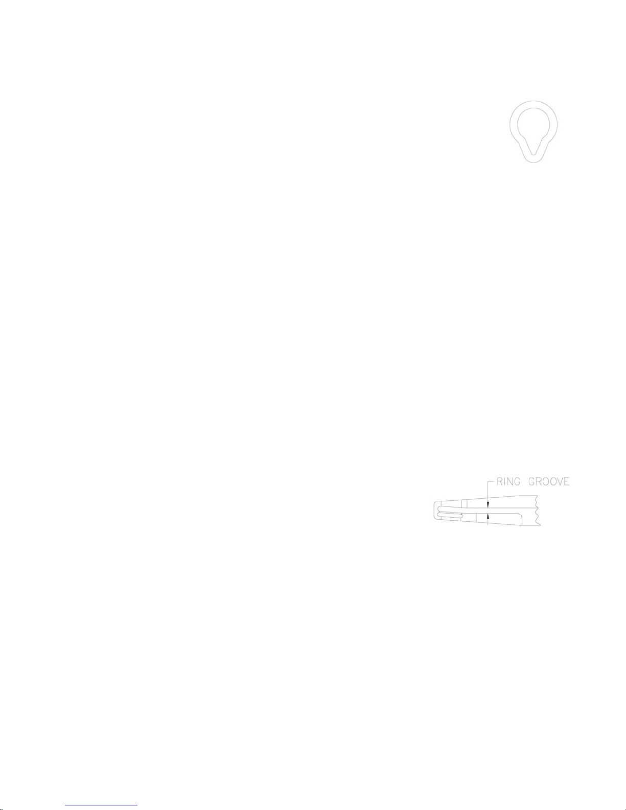
• Ring point not entering jaw A – Correct by chamfering tip of the
helix that the ring is entering as shown in Figure B.
• Rings only curling in one jaw – replace jaws
Page 4
Rev H 4-30-2010
Ring tear drops instead of forming
• Latch worn – replace latch
• Latch spring bent or broken (spring must hold latch tightly against
end of side plate and against jaws) – replace latch spring
• Feeder blade worn – replace feeder blade
• Defective rings
1. Burrs
2. Twisted
3. Not symmetrical
4. Wrong rings. Return samples of rings to your Vertex Fasteners representative
for testing.
Rings jam
• Magazine
1. Damaged magazine – replace magazine
2. Too many shims (ring passes under shoe without raising shoe; no control of ring)
– adjust see repair section
3. Too few shims (ring must be forced under shoe which “bottoms out” and may
deflect magazine) – adjust see repair section
4. Worn shoe – replace shoe
5. Frequent jamming can cause the shoe hole in the magazine to increase in size –
replace the magazine
6. Loose or lost rear magazine mounting screw (magazine is not supported
properly) – tighten or replace mounting screw
• Damaged or bent rail – replace rail
• Pusher spring defective – replace spring
• Feeder blade worn, broken or bent – replace feeder
blade
• Ring groove in jaw worn – replace jaw
• Defective rings
1. Burrs
2. Rings skewed on stick
3. Rings out of line on stick
4. Rings twisted
5. Rings not symmetrical
6. Poor tape to ring adhesion
7. Wrong rings. Return samples of rings to your Vertex Fasteners representative
for testing.
Rings don’t feed down magazine
• Pusher spring defective – replace spring
• Damaged magazine – replace magazine
• Damaged or bent rail – replace rail
Page 5

Rev H 4-30-2010
• Damaged pusher – replace pusher
• Defective rings
1. Undersized (tight on magazine)
2. Burrs
3. Rings twisted
4. Rings skewed on stick
5. Rings out of line on stick
6. Poor tape to ring adhesion
7. Wrong rings. Return tool and sample rings to your Vertex Fasteners
representative for testing.
Ring spitting
• Air pressure too high – verify air pressure
• Pusher spring loose – replace spring
• Magazine
1. Damaged magazine – replace magazine
2. Too many shims (ring passes under shoe without raising shoe; no control of ring)
– adjust see repair section
3. Too few shims (ring must be forced under shoe which “bottoms out” and may
deflect magazine) – adjust see repair section
4. Worn shoe – replace shoe
• Damaged or bent rail – replace rail
• Worn jaws – replace jaws (replace only in sets)
• Build up of material in jaw helix – remove build up of material
• Defective rings –
1. Burr on outside curve of ring
2. Rings skewed on stick
3. Rings out of line on stick
4. Rings not symmetrical
5. Rings twisted opposite to jaw helix
6. Wrong rings. Return samples of rings to your Vertex Fasteners representative
for testing.
Page 6

Rev H 4-30-2010
Ring Defects
Vertex Fasteners Hog Ring Tools are designed to operate with rings manufactured to standard
tolerances. Defective rings can be the cause of many ring-forming problems. Never use rings
that are too loose or otherwise defective. Below are some examples of defects that can
occur.
REPAIR
Note: Mineral spirits is recommended for cleaning tool and parts. Do not allow
rubber of handle to soak in mineral spirits as this will cause the rubber to
swell over time and become loose on tool. Wipe off immediately, dry parts
thoroughly before reassembly, use adequate ventilation.
Page 7

Rev H 4-30-2010
Internal Components of VA0278 C-Ring Tool
Page 8

Rev H 4-30-2010
Jaws, magazine and pusher assembly
To Disassemble
1. Remove nylock nuts VH0488, washers VH0221, and latch spring VC8102 from
the jaw screws VH0489.
2. Remove screws VH0491 from rear of feeder guide rail.
3. Remove jaw screws from tool this will allow magazine and pusher assembly,
latch VC8128 and jaws VC8129 and VC8130 with jaw bushings VC8107 to be
removed from tool.
4. Remove button head screw VH0033 from rail and magazine.
To Reassemble
1. Mount latch VC8128 onto side plate opposite magazine.
2. Install jaw bushings VC8107 into jaws VC8129 and VC8130. Lubricate bushings
with lithium grease VH0214 before installing.
3. Place jaws with bushings between side plates VC8123.
4. Slide magazine into position between spring spool bracket VC8127 and side
plate. Attach magazine assembly to rear of feeder guide rail using screw
VH0033 and blue Loctite (243). But do not tighten completely.
5. Insert jaw screws VH0489 through spring spool bracket, magazine, side plate,
jaw bushing, side plate, latch spring and washers. Secure with nylock nuts. Do
not over tighten, jaws must pivot freely.
6. Reattach feeder guide rail to rear of tool using screws VH0491.
7. Tighten button head screw VH0033.
Page 9

Rev H 4-30-2010
Piston and Piston Rod
To Disassemble
1. Disassemble jaws, magazine and pusher assembly as outlined above.
2. Remove button head screw VH0033 from trigger guard VC8116.
3. Remove (2) screws VH0032 with nylock nuts VH0490.
4. Remove side plates, trigger guard, trigger and roll pins. VC8123, VC8116,
VC8106 and VH0500.
5. Remove (4) rollers VC8104.
6. Remove remaining (2) screws VH0491 from rear of tool.
7. Remove end plate VC8108 and o-ring VH0496.
8. Remove bumper VC8136.
9. Push piston rod VC8125 towards rear of tool exposing piston VC8122.
10. Place tool into vise by clamping down on flat areas of piston rod (do not over
tighten vise jaws).
11. Apply heat if needed to breakdown thread lock adhesive on threaded end of
piston rod.
Page 10
Rev H 4-30-2010
12. Remove piston VC8122 with 9/16” open end or adjustable wrench.
13. Piston rod may now be removed from front of tool.
14. Remove o-ring VH0540.
15. Remove piston rod o-ring VH0464 from front of tool using o-ring pick.
To Reassemble
1. Install o-ring VH0464 into housing thru front of tool.
2. Slide piston rod VC8125 into front of tool. Be careful not to damage o-ring
VH0464 when pushing piston rod into housing, use lubrication.
3. Slide o-ring VH0540 onto piston rod from rear of tool.
4. Place o-ring VH0461 onto piston VC8122.
5. Lubricate piston o-ring liberally with grease VH0214.
6. Clean threads of piston rod and apply thread locker (Loctite 2760 “Red”) to
threads.
7. Slide piston with o-ring into housing end, aligning piston with piston rod. Be
careful not to damage piston o-ring when inserting piston, use grease VH0214.
8. Use 9/16” open end or adjustable wrench to tighten piston while holding flat
areas of piston rod.
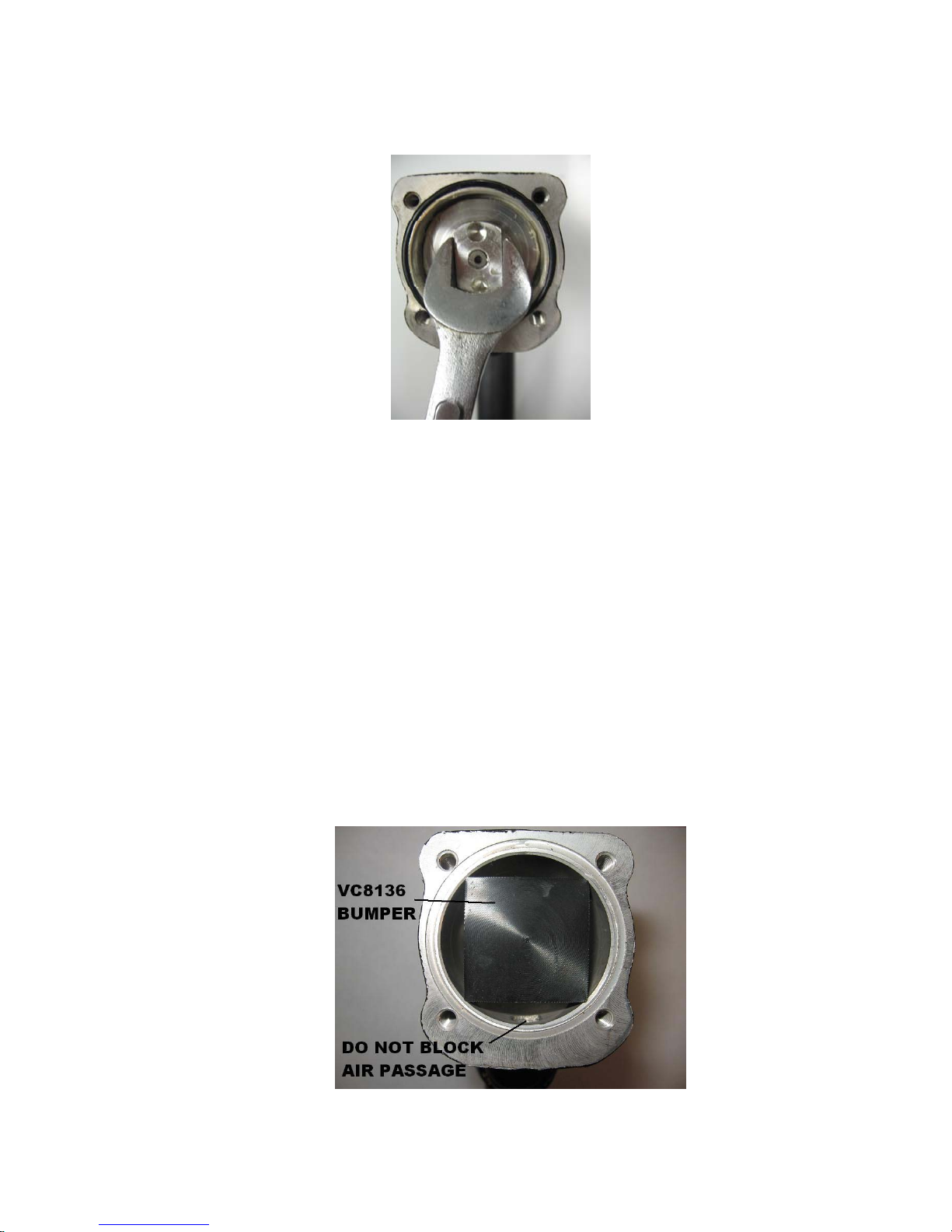
9. Install bumper VC8136 by pushing into housing.
Page 11
Rev H 4-30-2010
10. Place o-ring VH0496 into o-ring groove of housing.
11. Place end plate on rear of tool, properly aligned to housing and secure with (2)
screws VH0491, leaving mounting area for feeder guide open.
12. Place rollers VC8104 on roller pins VH0499. Grease will hold rollers in place
while assembling rest of tool.
13. Slide side plates into place on housing (slight force may be used to place side
plates onto housing).
14. Insert (2) screws VH0032 from magazine side of tool and install nylock nuts
VH0490.
15. Assemble trigger VC8106 and trigger guard VC8116 to side plates VC8123
with (3) roll pins VH0500.
16. Reassemble jaws, magazine, pusher assembly and remaining hardware as
outlined above.
Pusher and pusher spring
To Disassemble
1. Disassemble jaws, magazine and pusher assembly as outlined above.
2. Remove button head screw VH0033 from pusher VC8113 and spring VC8109.
3. Hold spring bracket VC8127 in vise by the ears, it is not necessary to remove
bracket from guide rail VC8119.
4. Drive slotted spring pin VH0498 thru bracket and spring VC8109. Remove old
spring.
To Reassemble
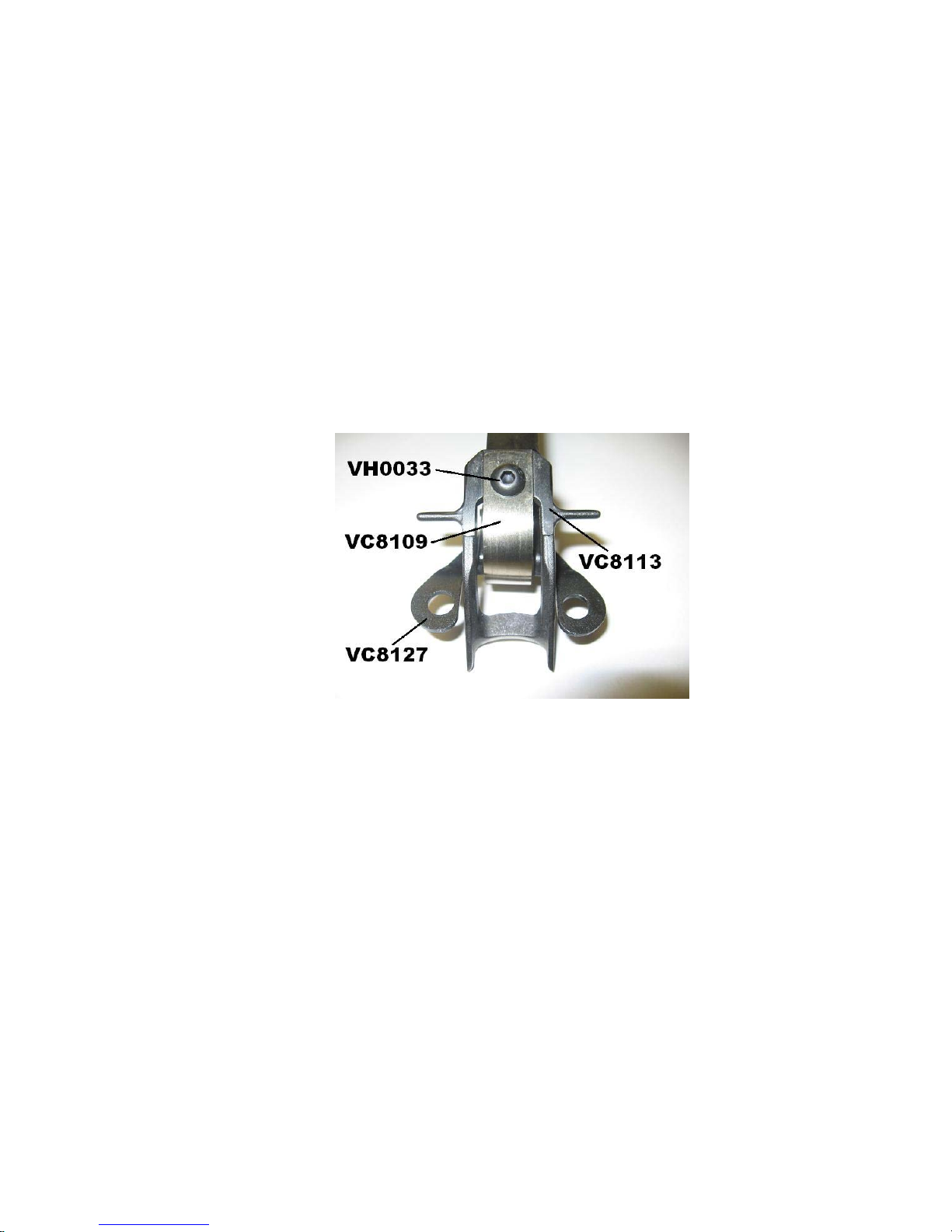
1. Mount new spring VC8109 onto spring bracket VC8127 using slotted spring pin
VH0498. Make sure spring is properly orientated (see diagram).
2. Attach spring VC8109 onto pusher VC8113 with button head screw VH0033
(feed spring thru large opening in pusher).
3. Reassemble jaws, magazine and pusher assembly as outlined above.
Page 12
Rev H 4-30-2010
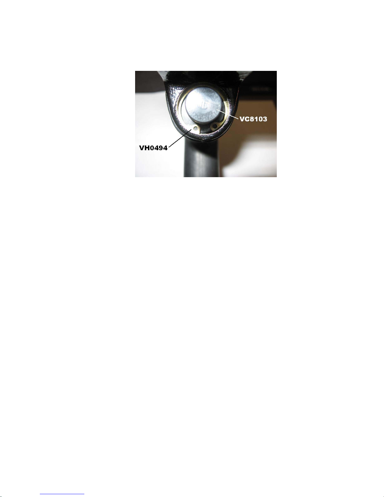
Valve
To Disassemble
1. Remove retaining ring VH0494, deflector VC8103 and spring VH0506.
2. Pull Valve rod VC8111 straight back out of tool.
3. Replace (5) o-rings VH0462.
4. Remove spool VC8105 by using long drift pin punch. From front of tool tap spool
out of body of tool. Note: The spool should never need replacement unless
physically damaged due to corrosion abuse etc.
5. Replace (5) o-rings VH0005.
To Reassemble
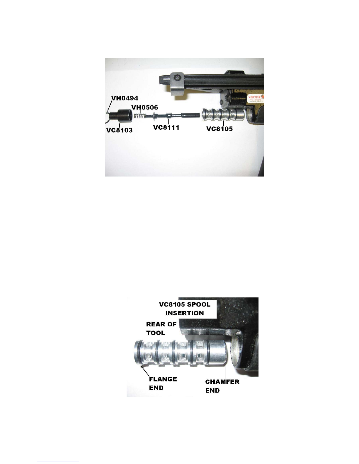
1. Use plenty of grease VH0214 on spool VC8105 and o-rings VH0005.
2. Insert spool into body from the rear, (see diagram for orientation) using deflector
VC8103 tap spool into place until flange of spool seats firmly in body.
3. Use light amount of grease VH0214 on valve rod VC8111 and o-rings VH0462.
4. Insert valve rod VC8111 into spool VC8105 until e-ring VH0497 seats against the
back of spool.
Page 13
Rev H 4-30-2010
5. Replace spring VH0506 onto end of valve rod VC8111.
6. Replace deflector VC8103 and hold in place with retaining ring VH0494. Make
sure that retaining ring snaps into internal groove of body.
Converting to Left Hand Tool
1. Remove (2) jaw screws VH0489, nuts VH0488, washers VH0221, latch spring
VC8102 and latch VC8128.
2. Remove (4) screws VH0491.
3. Remove magazine and pusher assembly.
4. Remove jaws VC8129 and VC8130 with bushings VC8107 and replace back in
opposite way.
5. Move latch VC8128 to opposite side.
6. Place magazine and pusher assembly on other side.
7. Replace latch spring and fasteners.
Page 14

REV
DESCRIPTION
BY
APPD
DATE
MATERIAL:
HEAT TREATMENT:
FINISH:
VERTEX FASTENERS INC.
3714 JARVIS AVENUE
SKOKIE, IL 60076 U.S.A.
DWG. NO.
SCALE
DATE
APPD
DWN BY
2003
C
TOL. UNLESS
SPECIFIED
INCHES
.X =
`.030
.XX =
`.015
.XXX =
`.005
ANGLES
`1/2~
1-13-04
C
C-RING TOOL ASSEMBLY
VC8000
JMW
THIS DOCUMENT AND THE DATA DISCLOSED HEREIN OR HEREWITH IS NOT TO BE REPRODUCED, US ED, OR DISCLOSED IN
WHOLE OR IN PART TO ANYONE WITHOUT THE PERMISSION OF VERTEX FASTENERS INC.
VC8100 HOUSING
1
VC8101
BLADE, FEEDER 1
VC8102 SPRING, LATCH
1
VC8103 DEFLECTOR
1
VC8104 ROLLER
4
VC8105 SPOOL 1
VC8106 TRIGGER
1
VC8107 BUSHING, JAW
2
VC8108
PLATE 1
VC8109 CONSTANT FORCE SPRING 1
VC8110 GUARD
1
VC8111 VALVE ROD
1
VC8112 MAGAZINE
1
VC8113 PUSHER
1
VC8114 SPRING
2
VC8115 CLIP, ANTI-BACKUP
1
VC8116 GUARD, TRIGGER 1
VC8117 SHIM, MAGAZINE, .010
AR
VC8119 RAIL, FEEDER GUIDE
1
VC8122 PISTON
1
VC8123 SIDE PLATE 2
VC8124 SHOE, MAGAZINE
1
VC8125 ROD, PISTON
1
VC8127 BRACKET, SPRING SPOOL
1
VC8128 LATCH
1
VC8129
JAW, UPPER 1
VC8130 JAW, LOWER
1
VC8131 LABEL, WARNING 1
VC8136
BUMPER 1
VC9124
LABEL 2
VH0005
O'RING, #016
VH0032 SHCS, 10 - 24 x 1 2
VH0033
BHCS, 10 - 32 x 1/4
3
VH0221
WASHER, 1/4
2
VH0459
PIN, SLOTTED SPRING, 3/32 x 3/8
2
VH0462
O-RING, #008
VH0464
O-RING, 011
1
VH0467
PIN, SLOTTED, 3/32 x 7/16
1
VH0486 PAN HEAD, 6 - 19 x 1/4 3
VH0488
NUT, NYLOCK, 1/4 - 28
2
VH0489
SHCS, 1/4 - 28 x 1 1/2
2
VH0490
NUT, NYLOCK, 10 - 24
2
VH0491 BHCS, 10 - 24 x1/2
4
VH0493
BRONZE SLEEVE BEARING
1
VH0494
RETAINING RING
1
VH0496
O-RING 030
1
VH0497
E-RING
1
VH0498
PIN, SLOTTED SPRING, 3/32 x 3/4
2
VH0499
PIN, DOWEL, 3/16 x 1/2
2
VH0500 PIN, SLOTTED SPRING, 1/8 x 11/16 3
VH0506
SPRING
1
VH0540
O-RING, #203
1
VH0641
O-RING, #218
-
PART # DESCRIPTION QT
A
ECN 400
JMW 8-6-04
B
ECN 433 REM VC8131 NOISE
SUP. & VH0014 PIN
JMW 12-22-04
C
ECN 605
JMW 1-9-06
D
D
ECN 723, WAS VH0495
JMW 11-14-06
E
ECN 748, CHANGE O-RING
QTY -, PART OF ASSY
JMW 1-26-07
/ ORDER NO. VA0278
MAR
VH0033
VH0032
VH0489
VH0486
VC8110
VC8112
VH0486
VC8115
VH0467
VC8114
VC8124
VC8109
VC8127
VH0033
VC8106
VC8116
VH0459
VC8119
VC8125
VC8101
VC8107
VC8130
VH0005
VH0462
VH0493
VC8122
VH0496
VC8108
VH0491
VH0494
VC8103
VH0506
VC8111
VH0497
VC8105
VC8100
VC8129
VC8107
VH0488
VC8102
VH0500
VC8128
VH0499
VC8104
VC8123
VH0490
VC8123
VC8117
VH0033
VC8113
VH0498
VH0221
VC8131
VC9124
VH0464
VH0540
MAR
MAR
VC8136
USE LOCTITE 2760
MAR
VH0641
MAR
MAR
Rev H 4-30-2010
Page 15

Rev H 4-30-2010
RECOMMENDED SPARE PARTS LIST
PART # DESCRIPTION NO. OF TOOLS
VC8100 HOUSING 0 0 1
VC8101 BLADE, FEEDER 1 2 3
VC8102 SPRING, LATCH 1 2 4
VC8103 DEFLECTOR 0 1 2
VC8104 ROLLER 4 8 16
VC8105 SPOOL 0 1 2
VC8106 TRIGGER 1 2 3
VC8107 BUSHING, JAW 2 4 6
VC8109 SPRING, CF 1 2 4
VC8110 GUARD 0 1 2
VC8111 VALVE ROD 0 1 2
VC8112 MAGAZINE 0 1 2
VC8113 PUSHER 0 1 2
VC8114 SPRING, SHOE 2 4 6
VC8115 CLIP, ANTI-BACKUP 1 2 3
VC8117 SHIM, MAGAZINE, .010 2 8 12
VC8119 RAIL, FEEDER GUIDE 0 1 2
VC8122 PISTON 0 1 2
VC8124 SHOE, MAGAZINE 0 1 2
VC8125 ROD, PISTON 0 0 1
VC8128 LATCH 1 2 3
VC8129 JAW, UPPER 1 2 3
VC8130 JAW, LOWER 1 2 3
VC8136 BUMPER 0 0 1
VH0005 O-RING, SPOOL 0 5 10
VH0032 SHCS, 10-24 X 1 2 2 4
VH0033 BHCS, 10-32 X 1/4 2 4 8
VH0221 WASHER 2 4 8
VH0459 PIN, SLOTTED SPRING 2 4 6
VH0462 O-RING, VALVE 5 10 20
VH0464 O-RING 0 2 4
VH0486 PAN HEAD, 6-19 X 1/4 1 2 4
VH0488 NUT, NYLOCK 2 4 8
VH0489 SHCS, 1/4-28 X 1 1/2 1 2 4
VH0490 NUT, NYLOCK 2 4 6
VH0491 BHCS, 10-24 X 1/2 2 4 8
VH0493 BUSHING 0 0 1
VH0494 RETAINING RING 0 0 1
VH0641 O-RING, PISTON 1 2 4
VH0496 O-RING 1 2 4
VH0497 E-RING, VALVE 0 1 2
VH0498 PIN, SLOTTED SPRING 1 2 4
VH0499 PIN, ROLLER 2 4 8
VH0500 PIN, ROLL 1 2 3
VH0506 SPRING, VALVE 0 1 2
VH0540 O-RING 0 1 2
1 5 10
 Loading...