

Vertex BriteStar Owner's Manual
BATTERY-FREE SOLAR AERATION
BriteStar Owner’s Manual
Battery Free Solar Aeration Systems
CHECK MATERIALS UPON DELIVERY
FOR PRODUCT DAMAGED IN DELIVERY: The solar aeration system was properly
packed and accepted by the freight carrier for shipment. It is their responsibility to
deliver the system in perfect condition.
APPARENT DAMAGE OR LOSS: If upon delivery the equipment or containers
indicate DAMAGE IN TRANSIT, such goods should be refused or not accepted until
the transportation company’s agent has noted such on the freight bill. A copy of
such bill will be given to you, noting the nature and extent of the damage. If any
part of shipment is LOST IN TRANSIT, have shortage noted on freight bill
by agent.
CONCEALED DAMAGE: If damage is discovered, that was not apparent upon
delivery, notify the transportation company immediately to inspect damaged
equipment. The inspector will be required to provide a “CONCEALED BAD ORDER”
report. Inspections must be requested within 15 days of delivery. Do not move
damaged goods from original point of delivery. Retain all original packing and
containers for inspection. File a “FULL VALUE REPLACEMENT” claim against the
transportation company.
CONGRATULATIONS!
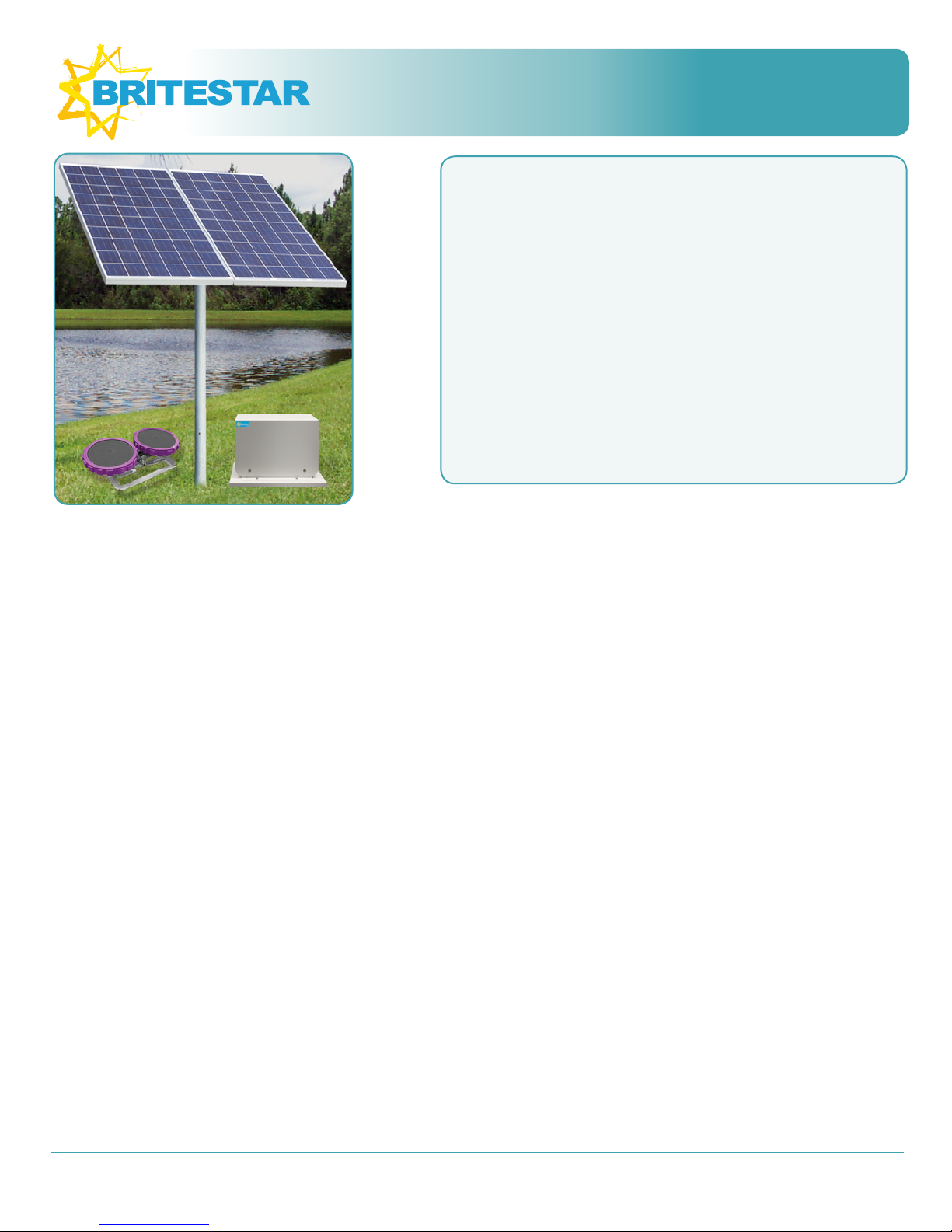
Your new BriteStar Solar Aeration System by Vertex Water Features
includes a BriteStar Aeration cabinet with pre-assembled conduit
connections, two high efficiency solar panels, pre-assembled racking
and Vertex XL AirStations.
PRODUCT WARRANTY
3 year warranty on all components, repair or replace any
defective part.
Not covered: Air filters and compressor maintenance kit parts
5 year AirStation “No Questions” replacement policy
5 year solar panel warranty
All claims must be made to Vertex Water Features or an Authorized
Dealer. The customer is responsible for return shipping of any goods
for warranty inspection. After inspection, if the product shows a
manufacturing defect, Vertex will replace or repair parts at no cost to
the customer. Should inspection indicate non-warranty failure (faulty
installation, vandalism, negligence, etc.) warranty will be voided.
The period for all warranty work is equal to the remaining time period
of the original new equipment warranty. Warranty claims are based
on the date you purchase the product: mail the warranty card, call
844-432-4303 or go to www.vertexwaterfeatures.com/registerwarranty
WARNING! VOIDS WARRANTY :
Installing cabinet in a very low elevation may allow flooding to
occur - warranty does not cover damage from flood water that
destroys the compressor and/or electronics.
Installing the cabinet in an unusually dirty environment.
Excessive airborne dirt, sand or grit entering the cabinet will
damage the system.
Call your dealer or Vertex Water Features for help resolving
installation problems.
*Vertex reserves the right to change information without notice, and makes no
warranty, express or implied, with respect to this information. Vertex shall not
be liable for any loss or damage, including consequential or special damages,
resulting from the use of this info, even if loss or damage is caused by Vertex
negligence or other fault.
MATERIALS YOU NEED TO PROVIDE
(1) 3.5 in. OD, 3 in. ID steel pole. Standard length is 8 ft., though you may cut
shorter if you prefer the array to be lower. NOTE: The pole must be buried a
minimum of 3 ft. deep
Bags of Concrete: (12) 60lb bags or (9) 80lb bags
(2) 1/2” x 16” Rebar
(1) Bag of gravel for each AirStation
TOOL CHECKLIST: Gather everything before starting
(2) 7/16 Wrenches
(2) 9/16 Wrenches
(2) 3/4 Wrenches
A-Frame Ladder
Compass
Flat head screw driver
Level
Phillips Head Screwdriver
Post-hole digger
Shovel
Tape Measure
SAFETY NOTES
Please read the following instructions carefully before installing and operating your
system. Failure to follow the recommendations in this section may result in personal
injury or rescinding of the warranty agreement.
When near water always wear an approved life jacket and follow all water safety
guidelines.
Locate the cabinet on a solid support with adequate strength for the weight of
the unit.
Never push objects of any kind into the slots in the covers, as they may touch
dangerous voltage points or short out parts that could result in a risk of fire or
electrical shock.
Never override or “cheat” electrical or mechanical interlock devices.
Never attempt any maintenance or other activity that is not specified in
the user manual, or that is not specifically directed by an authorized Vertex
representative.
Never operate the system if unusual noises or odors are detected. Turn system
off by turning the breaker to the off position, and call Vertex to correct any
problems.
Before performing any maintenance and troubleshooting, disconnect the
electricity by turning the breaker to the off position.
Hours of Operation: M-F, 8am – 5pm EST © Vertex Water Features
(844) 432-4303 www.vertexwaterfeatures.com info@vertexwaterfeatures.com
Vertex Water Features
2
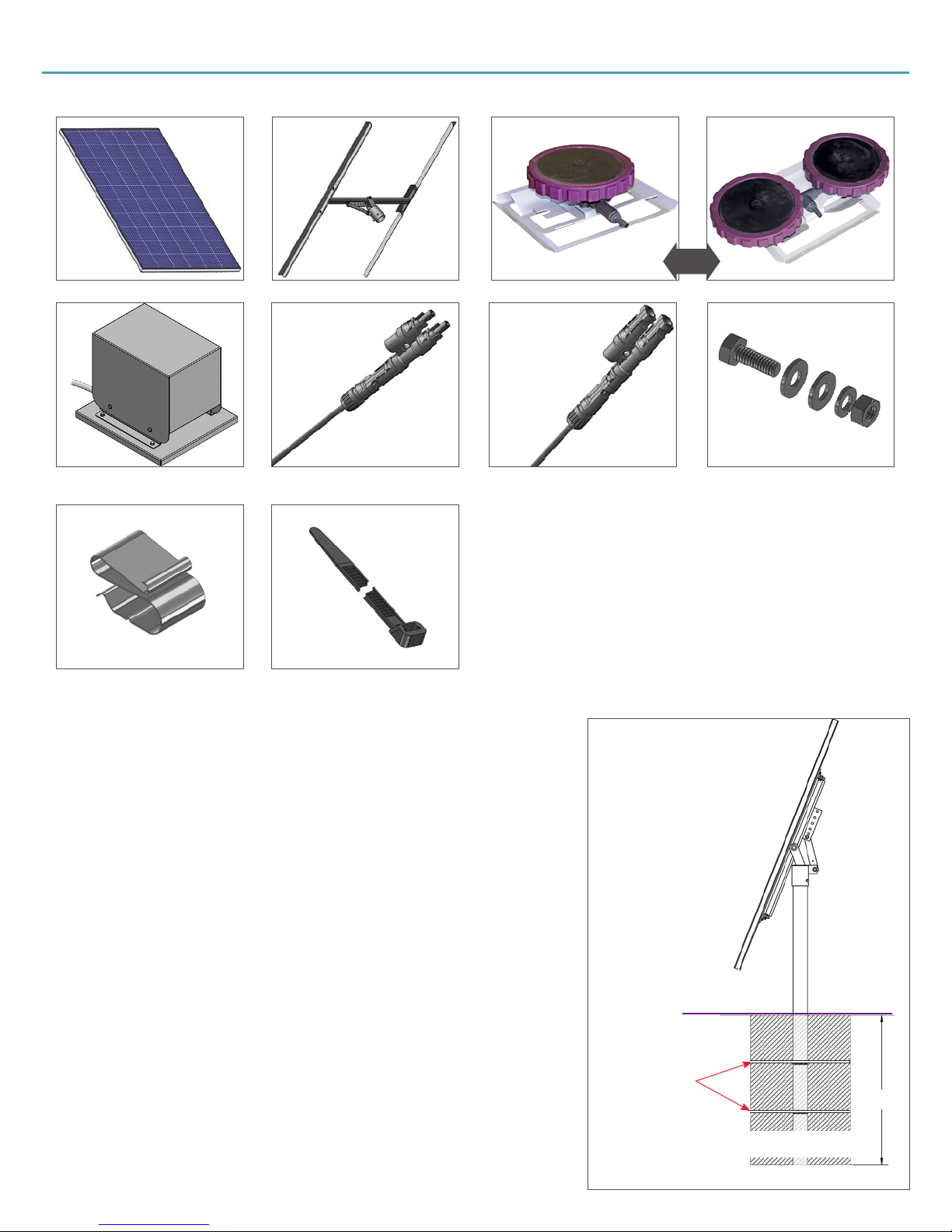
SYSTEM MATERIALS LIST: Verify that you received everything
OR
(2) High Efficiency Solar Panels (1) Assembled Top of Pole Racking (1, 2, or 3) XL1 AirStations (1) XL1 and (1) XL2 AirStation
(1) Prewired BriteStar
Aeration Cabinet
(4) Panel Cable Clips (10) Tywraps
(1) 15’ Male MC4 Extension Cable
with MC4 Coupler
(1) 15’ Female MC4 Extension Cable
SOLAR AND CABINET INSTALLATION
SITE SELECTION
Locate solar panels facing south where there is no shading from early morning to late
afternoon.
Be aware of tall objects such as buildings, poles, and trees whose shadows will
decrease the pumping rate. Even slight shading of solar panels significantly reduces
power output.
Solar panels face south in the northern hemisphere and north in the southern
hemisphere.
If installing close to pond, install far enough inland to avoid flooding of the compressor
cabinet.
with MC4 Coupler
3.5 IN. OD GALVANIZED PIPE
- 8’ for Normal height:
5’ above ground
- 6’ for low profile - shown:
3’ above ground
(8) Panel Racking Bolt sets
15° TILT
POLE INSTALLATION: SEE FIGURE 1
NOTE: Use a tape measure to get correct depth and width
In windy conditions, stress is put on the pole’s foundation due to the surface area of the
array and if the concrete mixture and curing process is less than perfect some shrinking of
the concrete occurs allowing the array pole to rotate in the concrete.
Pole should be 3.5 in. OD, 3 in. ID and a maximum length of 8 ft.
Using a shovel and post-hole digger, dig a hole a minimum of 3 ft. deep by 2 ft. wide.
To prevent the array from rotating, the pole should be drilled out with a 5/8” bit to
allow ½” rebar cut to a 16” length to be hammered into the pole at a cross angle in
the concrete. Locate the holes for the two rebar crosspieces by measuring up from the
bottom.
Place pole in the center of the hole and begin pouring the mixed concrete.
During pouring the concrete continue to adjust the levelness of the pole using a level.
GROUND LEVEL
1 FT. DOWN
1/2” X 18” REBAR
3 FT.
2 FT. DOWN
18 IN. BY 3 FT. HOLE
FILLED WITH CONCRETE
Figure 1: Pole Installation
GROUNDING: NEC ARTICLE 690
We recommend grounding your equipment according
to National Electrical Code (NEC) regulations. If you
have any doubts on proceeding yourself, contact your
local electrician to install the grounding rod and ground all
equipment properly.
INSTALLING PANEL RACKING: SEE FIGURE 3
The racking is shipped preassembled.
Line up the mounting sleeve with the top of pole and
lower into place.
Panels must face south [A] - use a compass to achieve
the correct orientation.
Mark the pole and sleeve with a permanent marker for
alignment purposes
Using a 9/16 wrench tighten the two set bolts [B] to 32-
34 ft.-lbs of torque.
INSTALLING PANELS: SEE FIGURE 4
Set the racking to the 15 degree setting to install panels
Place one panel on the racking and line up the panel
with the mounting holes on the racking
Using the provided fasteners loosely fit the panels on
the racking.
After panel is fitted with all fasteners in place tighten
down all the fasteners to 6-8 ft.-lbs of torque.
Repeat these steps for the second panel.
After panel installation, adjust tilt to desired angle.
A STRONGBACK -
POINT IT SOUTH
B SET BOLTS
Figure 3: Panel Racking Installation
Owners Manual
MOUNTING SLEEVE
MOUNTING POLE
3
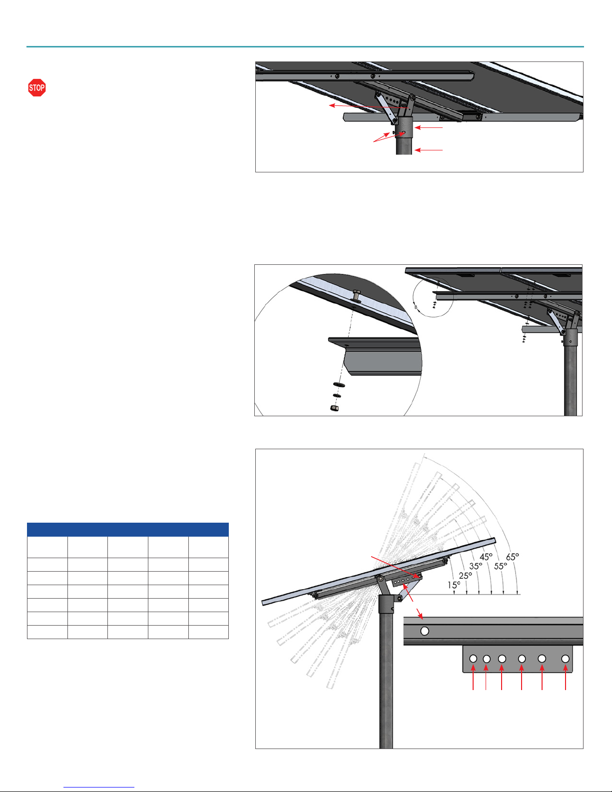
PANEL ORIENTATION: SEE FIGURE 5
The tilt angle should be adjusted to capture optimal
sunlight.
Remove the 3/8 bolt from the support bar [C].
Insert 3/8 bolt in the correct elevation set point for your
location and the season listed below.
Tighten the nut on the opposite side.
Best Solar Panel Angle by Season
Your
Latitude
25° 15 25 45 25
30° 15 25 45 25
35° 15 35 55 35
40° 15 35 55 35
45° 15 45 65 45
50° 25 45 65 45
Summer
JUN 21
Autumn
SEP 21
Winter
DEC 21
Spring
MAR 21
Figure 4: Installing Panels
C 3/8 BOLT
SUPPORT BAR
15°25°35°45°55°65°
ELEVATION SET POINT GAUGE
Figure 5: Panel Orientation
 Loading...