

Verterx Standard VXR-9000E Operating Manual
www.hfelectronics.be
VXR-9000E
RACK MOUNT REPEATER
OPERATING MANUAL
Vertex Standard LMR, Inc.
www.hfelectronics.be
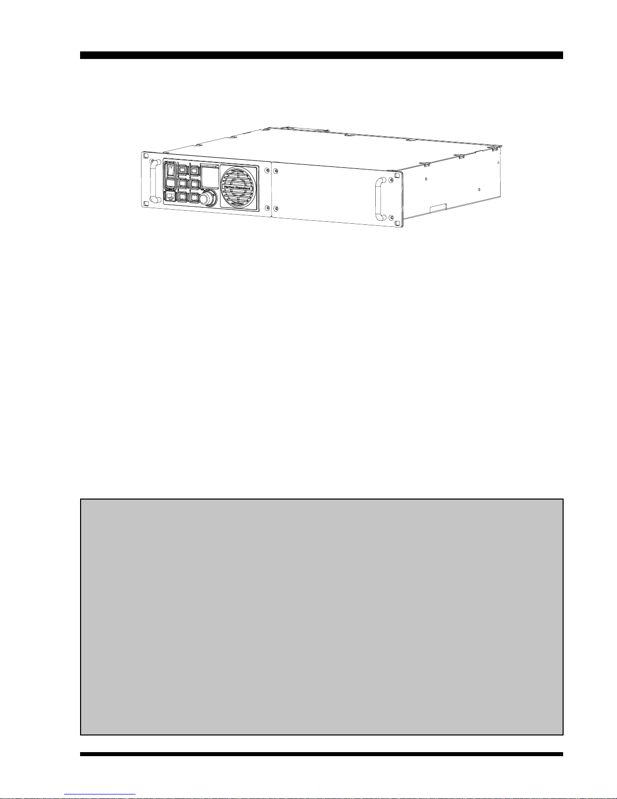
The VXR-9000E is commercial-grade 25-watt FM repeater designed to provide reliable two-way full-duplex communications over a wide range of environmental conditions.
Designed to mount in a standard 19-inch rack, the VXR-9000E is crafted using the latest computer-aided design and
manufacturing processes, to ensure a high level of reliability to users. Important channel frequency data is stored in
EEPROM, and is easily programmable by a Servicing Technician or Dealer using an IBM compatible personal computer and the FIF-10A (or FIF-12) + CT-104A USB Programming Interface and CE60 Software.
Please take a few minutes to read this manual carefully. The information presented here will allow you to derive
maximum performance from your VXR-9000E. After reading it, keep this manual handy for quick reference, in case
questions arise later on.
Important Note: Internal service work, programming, and accessory installations should only be performed by your
authorized Vertex Standard Dealer. Dangerous conditions and/or possibly illegal operation may result from improper setup, programming, or internal modifications.
SAFETY/WARNING INFORMATION
The antenna(s) used for this transmitter must be fixed-mounted on outdoor permanent structures with a
separation distance of at least 74 cm from all persons during normal operation and must not exceed an antenna gain of 0 dBd. This device must be restricted to work related operations in an Occupational/Controlled
RF exposure Environment, not exceeding a maximum transmitting duty factor of 50%. The antenna(s) used
with this device must satisfy the antenna co-location requirements of 47 C.F.R. 1.1307(b)(3).
NOTICE!
Do not modify this repeater for any reason.
Refer service of this repeater to qualified technicians only.
When the repeater become abnormal, such as the overheating, smoke smell of burning, etc., turn the main
power switch off and disconnect the Main Power Source connector from the rear of the VXR-9000E immediately. Also disconnect any backup power source you may have connected to the rear of the VXR-
9000E.
Do not place any combustible material near the repeater.
Do not spray any liquid over the repeater.
Ensure that the power and antenna connections are securely made, using cables with excess capacity for
the power being utilized.
INTRODUCTION
VXR-9000E RACK MOUNT REPEATER OPERATING MANUAL 1
www.hfelectronics.be
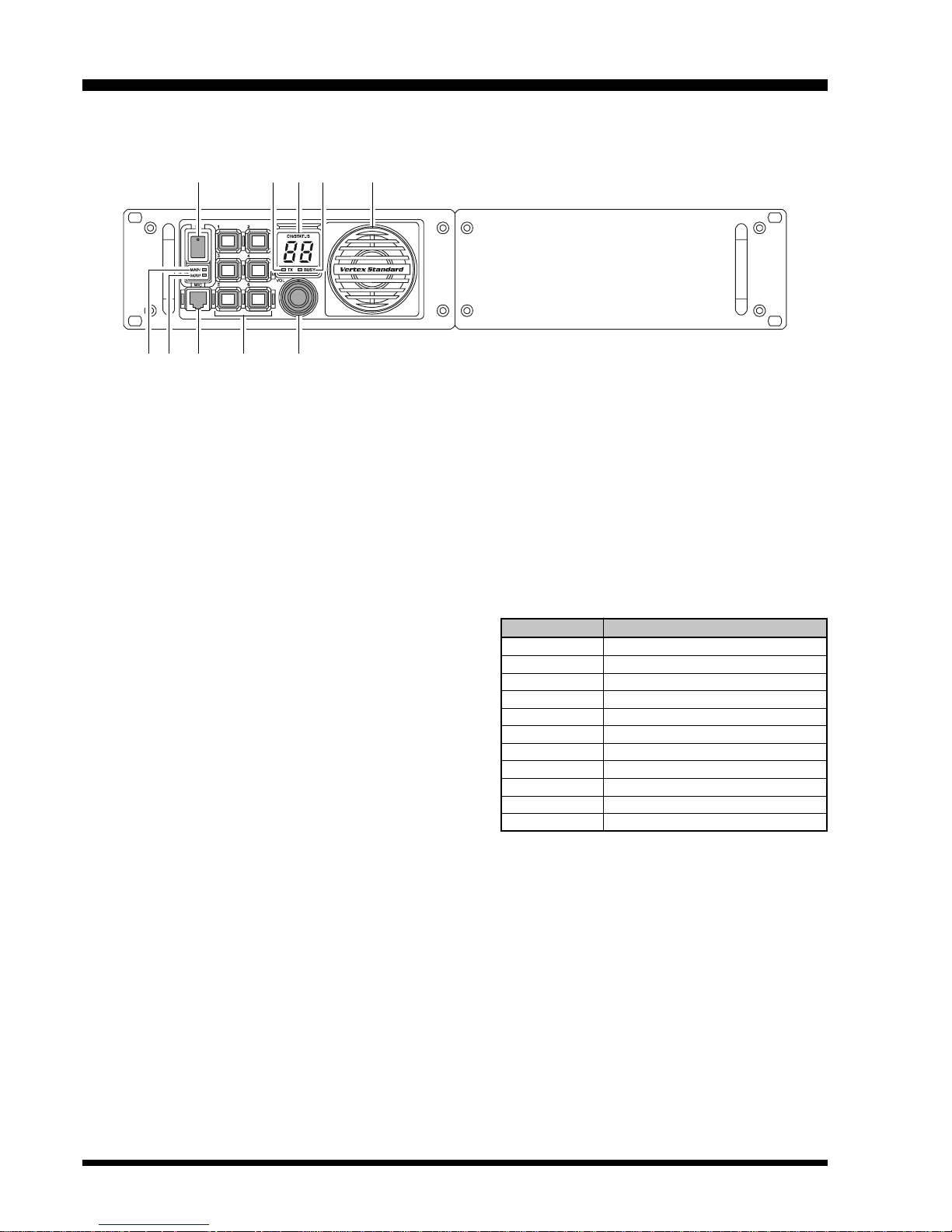
POWER (O/I) Switch
This is the main power switch for the repeater.
Power Indicator (MAIN
)
This LED glows green when the main power source
is used.
Power Indicator (BACKUP
)
This LED glows red when the backup power source
is used.
MIC Jack
Connect the microphone plug to this jack. This jack
is also used for writing and reading channel frequency or other configurations via the USB Port of
the PC on which the clone editor (CE60) is running.
Programmable Function (PF) Key
Six pushbuttons on the front panel are programmable function (PF) keys, each with an orange indicator inside. Each key can be programmed with
two functions, one for a “long” press and one for a
“momentary” press. The PF key functions may be
customized, via programming by your VERTEX
STANDARD dealer, to meet your communications
network requirements. Note that some functions
may require the purchase of optional internal accessories. The possible PF key features and functions
are explained on the pages to follow.
VOL Knob
This control knob adjusts the output level of the front
speaker and external speaker jack on the back panel.
TX Indicator
This LED glows red when the repeater is transmitting.
Numeric Display
This display consists of two 7-segment LEDs, indicating the channel number during normal operation.
If an abnormal condition arises, an error code will be
displayed:
DISPLAY DESCRIPTION
01 - 32 Channel Number
PC Clone Active
UL PLL Unlock
HI High temperature in PA Unit
SC Scan Active
LC Front Panel Keys are Locked
E1 PTT key is Disabled
E2 Cooling Fan is Disabled
E5 Low Voltage in Backup Battery
E7 PA Unit Abnormality
E3, E4, E6 , E9 Contact your Dealer
BUSY Indicator
This LED glows green when the receiving channel
is busy.
Speaker
The internal speaker is located here.
FRONT PANEL CONTROLS & CONNECTORS
VXR-9000E RACK MOUNT REPEATER OPERATING MANUAL2
www.hfelectronics.be
CH DOWN
Press (or Press and hold in for one second) the PF key
assigned to “CH Down” to step to the next-lower operating channel.
CH UP
Press (or Press and hold in for one second) the PF key
assigned to “CH Up” to step to the next-higher operating channel.
COMPANDER
Press (or Press and hold in for one second) the PF key
assigned to “Compander” to turn the Compander circuit “On” or “Off” (toggle). This function is only activated on the “Narrow Channel Spread” of the “Base
Transceiver” mode.
The Compander IC contains two variable gain circuits
configured for compressing and expanding the dynamic
range of the repeater’s transmitted and received audio
signal. When you enable this function, the signal-tonoise ratio can be improved by reducing the transmitted audio dynamic range.
CTCSS/DCS ENC
Press (or Press and hold in for one second) the PF key
assigned to “CTCSS/DCS Enc” to turn the CTCSS/DCS
Encoder “On” or “Off” (toggle).
CTCSS/DCS DEC
Press (or Press and hold in for one second) the PF key
assigned to “CTCSS/DCS Dec” to turn the CTCSS/DCS
Decoder “On” or “Off” (toggle).
CW ID
Press (or Press and hold in for one second) the PF key
assigned to “CW ID” to turn the CW Identifier feature
“On” or “Off” (toggle).
When the CW ID feature is set to “On,” your station’s
callsign will be superimposed on the outbound signal,
in Morse Code, at the beginning of every transmission.
Programming of the callsign is performed by your
VERTEX STANDARD dealer.
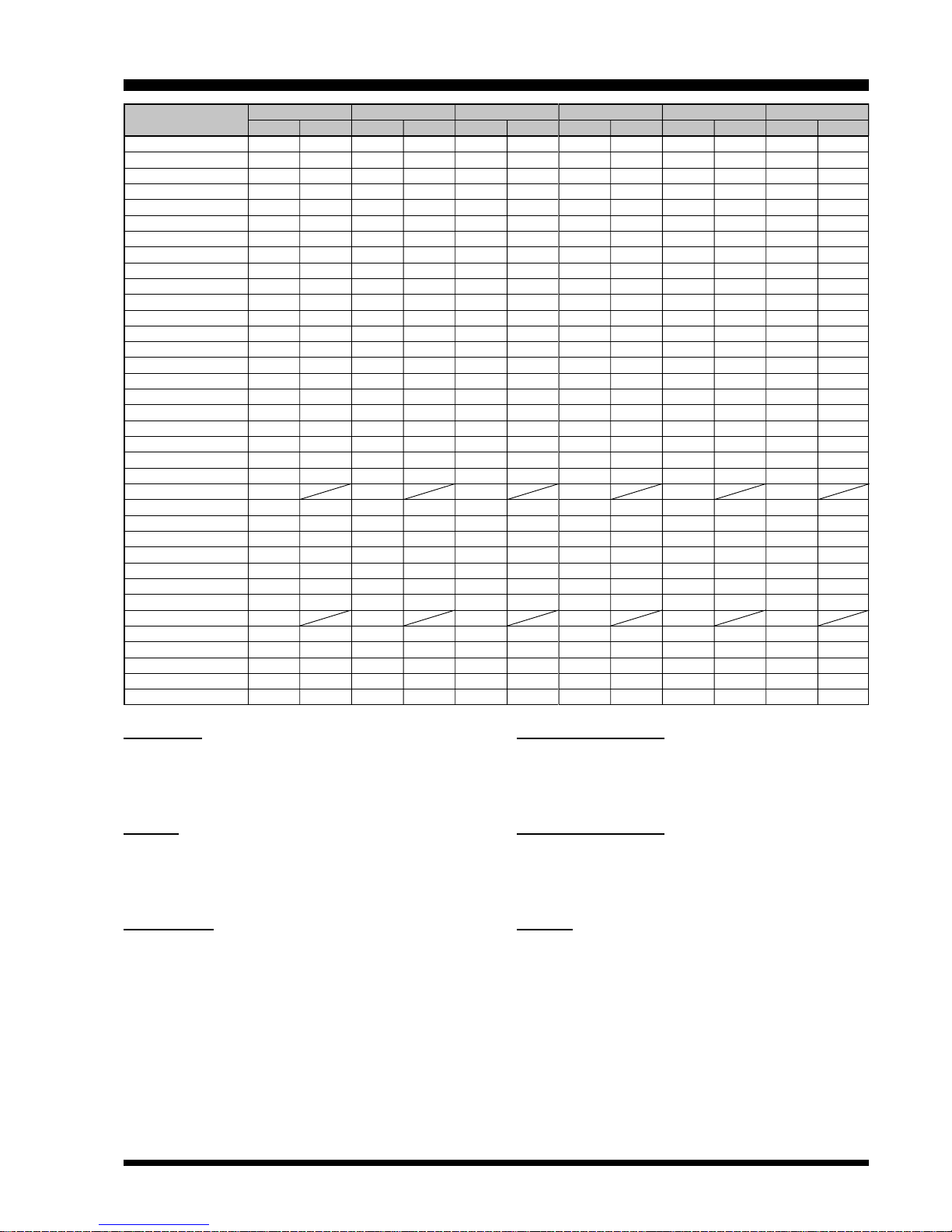
FUNCTION
CH DOWN
CH UP
COMPANDER
CTCSS/DCS ENC
CTCSS/DCS DEC
CW ID
TWO TONE DEC
CW ID SIGNAL
CW MESSAGE 1
CW MESSAGE 2
CW MESSAGE 3
CW MESSAGE 4
CW MESSAGE 5
CW MESSAGE 6
CW MESSAGE 7
CW MESSAGE 8
DC POWER SAVE
ENCRYPTION
ENCRYPTION CODE
KEY LOCK
LOCAL PTT
MONITOR
MONITOR M
MULTI TONE
PANEL INDICATOR
REMOTE
REPEAT
RESET
SCAN
SQUELCH
TEST TONE
TEST TONE M
TOT
TRANSMIT
TX POWER MID
TX POWER LOW
PF-1 KEY
P
RESSPRESS
& H
OLD
PF-2 KEY
P
RESSPRESS
& H
OLD
PF-3 KEY
P
RESSPRESS
& H
OLD
PF-4 KEY
P
RESSPRESS
& H
OLD
PF-5 KEY
P
RESSPRESS
& H
OLD
PF-6 KEY
P
RESSPRESS
& H
OLD
PROGRAMMABLE FUNCTION (PF) KEY DETAILS
VXR-9000E RACK MOUNT REPEATER OPERATING MANUAL 3

www.hfelectronics.be
MONITOR
Press (or Press and hold in for one second) the PF key
assigned to “Monitor” to cancel CTCSS and DCS squelch
decoding, so as to enable reception of signals present
on the channel that do not contain a matching CTCSS
tone or DCS code.
MONITOR M
This function provides to “Monitor” to cancel CTCSS
and DCS squelch decoding, so long as the PF key assigned to “Monitor M” is pressed and held in.
MUL TI TONE
Press (or Press and hold in for one second) the PF key
assigned to “Multi Tone” to switch the Tone Table between “Main” and “Sub.”
PANEL INDICATOR
Press (or Press and hold in for one second) the PF key
assigned to “Panel Indicator” to turn the Front Panel’s
Illumination “On” or “Off” (toggle).
REMOTE
Press (or Press and hold in for one second) the PF key
assigned to “Remote” to toggle the operating mode between the “Remote” mode and “Local” mode.
When the “Remote” mode is selected, the repeater operates according to the control instructions received from
the external device (connected to the ACC jack on the
rear panel). While in the “Local” mode, the repeater operates from the front panel’s PF keys.
REPEAT
Press (or Press and hold in for one second) the PF key
assigned to “Repeat” to toggle the operating mode between the “Repeater” mode and “Base Transceiver”
mode.
For normal operation, set this key to the “Repeat” mode.
When the “Base Transceiver” mode is selected, you can
speak into the microphone to use this repeater as a transceiver.
RESET
Press (or Press and hold in for one second) the PF key
assigned to “Reset” to reset (same function as the
POWER switch “off” and “on”) the repeater.
TWO TONE DEC
Press (or Press and hold in for one second) the PF key
assigned to “Two Tone Dec” to turn the 2-Tone Decoder
“On” or “Off” (toggle).
CW ID SINGLE
Press (or Press and hold in for one second) the PF key
assigned to “CW ID Single” to send the station callsign,
via Morse Code, once. Programming of the callsign is
performed by your VERTEX STANDARD dealer.
CW MESSAGE 1 - CW MESSAGE 8
Press (or press and hold in for one second) the PF key
assigned to “CW Message 1 - 8” to send a pre-programmed Morse Code message on the transmitted signal. Programming of the message(s) is performed by
your VERTEX STANDARD dealer.
DC POWER SAVE
Press (or Press and hold in for one second) the PF key
assigned to “DC Power Save” to turn the DC Power Save
feature “On” or “Off” (toggle).
When DC Power Save feature is set to “ON,” activate
the various power save feature (determined from your
VERTEX STANDARD dealer) while the repeater operates from the Backup Power Source.
ENCRYPTION
Press (or Press and hold in for one second) the assigned
PF key of the “Encryption” to turn off the Optional Encryption Unit temporarily.
ENCRYPTION CODE
Press (or Press and hold in for one second) the assigned
PF key of the “Encryption Code” to select the Encryption Code (determined from your VERTEX STANDARD
dealer; require the FVP-35 Rolling Code Encryption
Unit).
KEY LOCK
Press (or Press and hold in for one second) the PF key
assigned to “Key Lock” to lock the repeater’s front panel
keys (except “Key Lock” key); this feature can be enabled to prevent repeater settings from being disturbed.
LOCAL PTT
Press (or Press and hold in for one second) the PF key
assigned to “Local PTT” to enable (“On”) or disable
(“Off”) operation using a PTT switch connected to the
front panel’s Microphone Jack.
PROGRAMMABLE FUNCTION (PF) KEY DETAILS
VXR-9000E RACK MOUNT REPEATER OPERATING MANUAL4
 Loading...