

Verterx Standard VX-2200, VX-2200 LTR Operating Manual
VX-2200
OPERATING MANUAL
(
LTR
)
SERIES
4-8-8 Nakameguro, Meguro-Ku, Tokyo 153-8644, Japan
Vertex Standard LMR, Inc.
Congratulations!
You now have at your fingertips a valuable communications tool: a VERTEX STANDARD two-way radio! Rugged, reliable and easy to use, your VERTEX STANDARD radio will keep you in constant touch with your colleagues for years to come,
with negligible maintenance downtime.
Please take a few minutes to read this manual carefully. The information presented
here will allow you to derive maximum performance from your radio, in case questions arise later on.
We’re glad you joined the VERTEX STANDARD team. Call on us anytime, because communications is our business. Let us help you get your message across.
NOTICE !
There are no owner-serviceable parts inside the transceiver. All service jobs
must be referred to an authorized VERTEX STANDARD Service Representative. Consult your Authorized VERTEX STANDARD Dealer for installation of optional accessories.
SAFETY/WARNING INFORMATION
WARNING - DO NOT operate the VX-2200 (LTR) radio when any person(s)
(bystanders) outside the vehicle are within the distances shown in the chart at
the bottom of this section.
Safety Training information:
Antennas used for this transmitter must not exceed an antenna gain of 0 dBd.
The radio must be used in vehicle-mount configurations with a maximum
operating duty factor not exceeding 50 %, in typical Push-to-Talk configurations.
This radio is restricted to occupational use, work related operations only where
the radio operator must have the knowledge to control the exposure conditions of its passengers and bystanders by maintaining the minimum separation distance shown below.
Failure to observe these restrictions will result in exceeding the FCC RF
exposure limits.
Antenna Installation:
For rear deck trunk installation, the antenna must be located at least the following distance away from rear-seat passengers in order to comply with the
FCC RF exposure requirements.
For roof top installations, the antenna must be placed in the center of the roof.
1.64 Feet (0.50 m
Unsafe Radiation Distance
VHF Model
)
UHF Model
1.35 Feet (0.41 m
)
INTRODUCTION
The VX-2200(LTR) Series are full-featured FM transceivers designed for flexible
mobile and base station business communications in the VHF or UHF Land Mobile
bands. These transceiver are designed for reliable business communications in a
wide variety of applications with a wide range of operating capability provided by
their leading-edge design.
The 250-group memories can each be programmed with a 8-character group name.
Important channel frequency data is stored in EEPROM and flash memory on the
CPU, and is easily programmable by dealers using a personal computer and the
VERTEX STANDARD Programming Cable and CE94 Software.
The pages which follow will detail the many advanced features provided on the VX-
2200(LTR) Series transceiver. After reading this manual, you may wish to consult
with your Network Administrator regarding precise details of the configuration of
this equipment for use in your application.
For North American Users Regarding 406 MHz Guard Band
The U.S. Coast Guard and National Oceanographic and Atmospheric Administration have requested the cooperation of the U.S. Federal Communications Commission in preserving the integrity of the protected frequency range
406.0 to 406.1 MHz, which is reserved for use by distress beacons. Do not
attempt to program this apparatus, under any circumstances, for operation in
the frequency range 406.0 - 406.1 MHz if the apparatus is to be used in or
near North America.
VX-2200 (LTR) SERIES OPERATING MANUAL 1
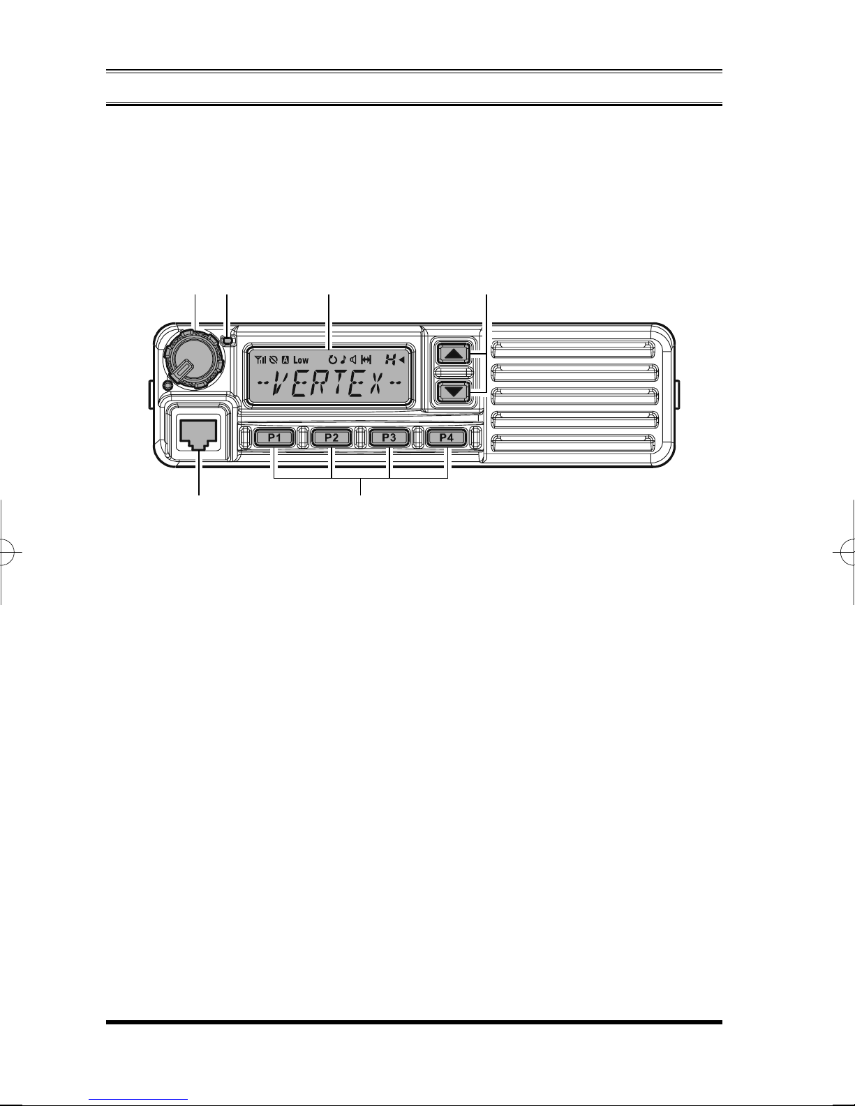
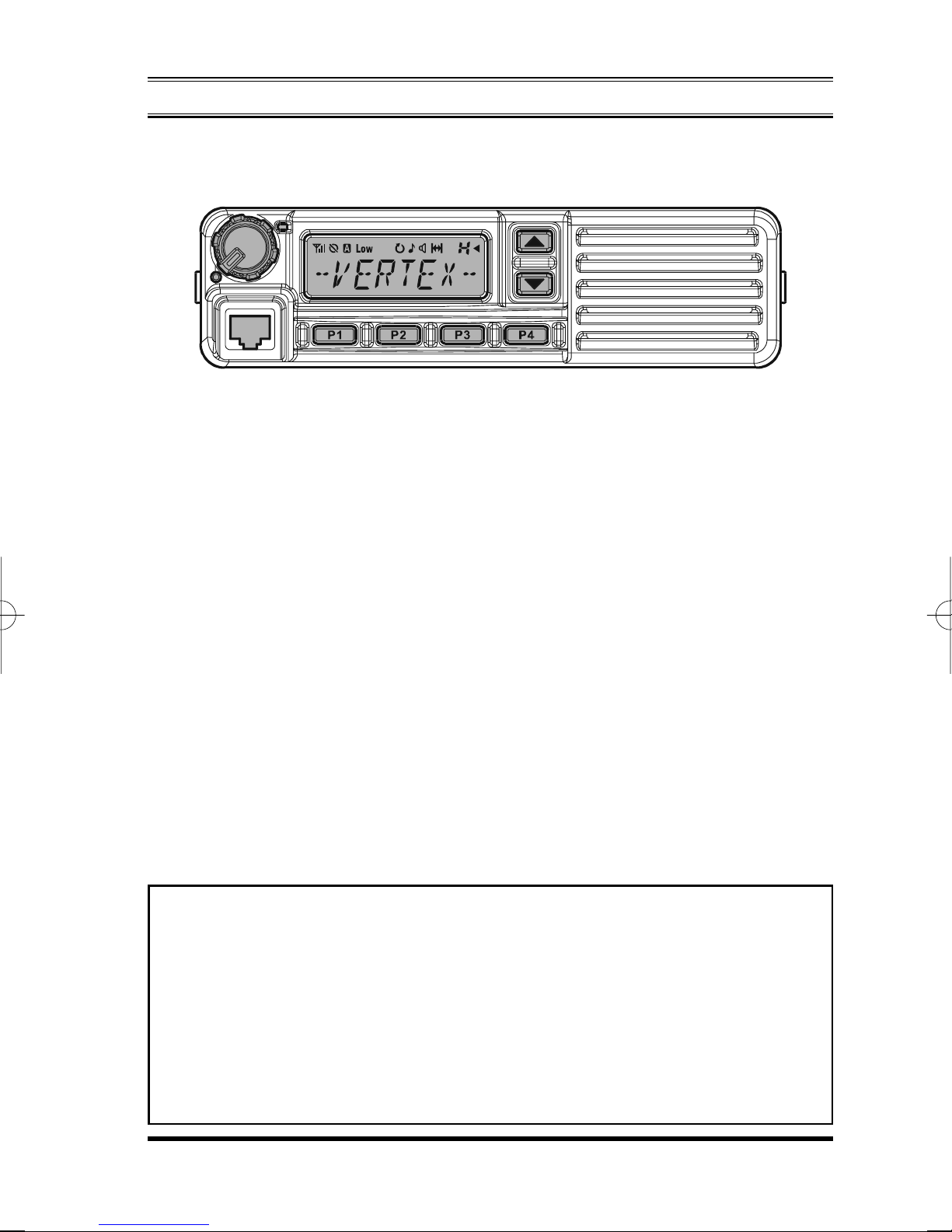
CONTROLS & CONNECTORS
Front Panel
Important! - All buttons located on the Front Panel are Programmable Function
(PF) Buttons, configured according to your network requirements and programmed
by your VERTEX STANDARD dealer. The instructions below describe a typicallyconfigured radio.
VOL/PWR Knob
Turn this control clockwise to turn the radio on and to increase the volume.
Turn it counterclockwise into the click-stop to turn the radio off.
Microphone Jack
Connect the microphone plug to this jack.
[P1] - [P4]
These buttons can be set up for special applications, such as High/Low power
selection, Monitor, Talk-Around, etc., as determined by your network requirements and programmed by your VERTEX STANDARD dealer.
[]/[]
In the factory default, pressing either button changes the current group (and
displayed group number or name). Holding in either button for more than 1.5
second causes the radio to begin stepping (repeatedly) upward or downward
through the groups.
Buttons (Programmable Function Buttons)
Buttons (Programmable Function Buttons)
VX-2200 (LTR) SERIES OPERATING MANUAL2
CONTROLS & CONNECTORS
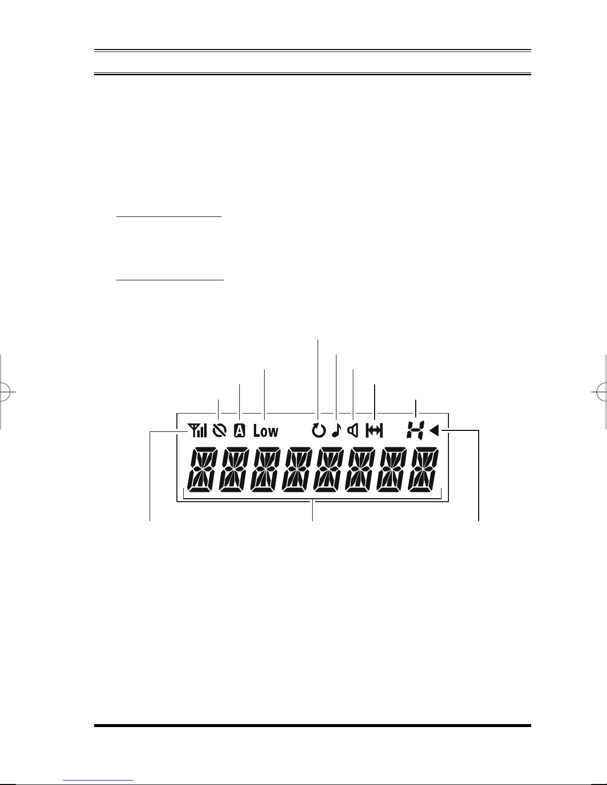
LCD (Liquid Crystal Display)
The display includes a 8-character alpha-numeric section showing group name
tags/identity information and error messages, and an upper icon row displaying
feature status (see below).
TX/BUSY Indicator
Indicates Transceiver’s Transmit/Receive Status
CONVENTIONAL ZONE
Steady Red: Transmitting in progress
Steady Green: Signaling Off
Blinking Green: Busy Channel/Squelch Off
LTR TRANKING ZONE
Steady Red: Transmission in progress
Steady Green: Zone Busy
“Scan” is activated
“Call” indicator
Low Transmt Power Mode
“AUX A” Port is activated
“Encryption” is enabled Home Zone/Group
Receiver Monitor
“Talk-Around” is enabled
RSSI Indicator (four steps)
VX-2200 (LTR) SERIES OPERATING MANUAL 3
8 Character Alpha-numeric Display
“Zone Scan” is enabled
on the current Zone
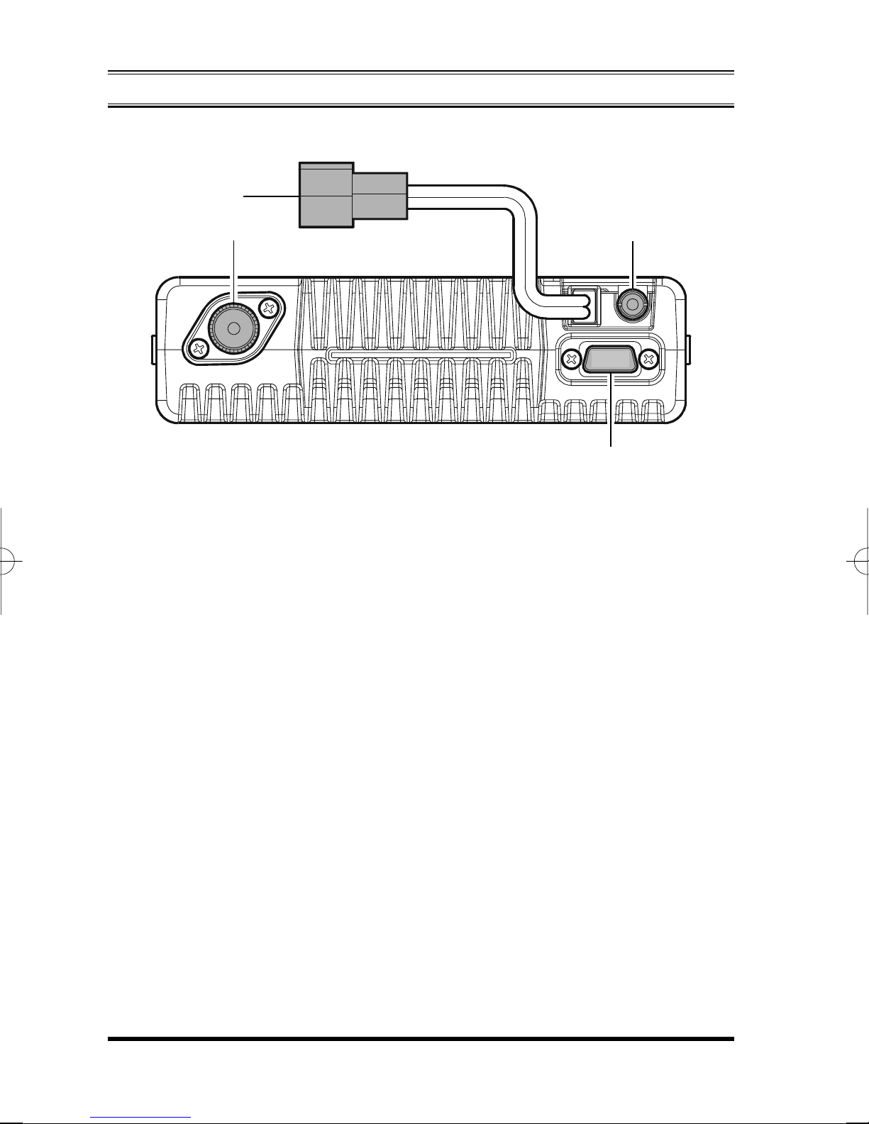
Rear Panel
CONTROLS & CONNECTORS
13.6V DC Cable Pigtail with Connector
The supplied DC power cable must be connected to this 2-pin connector. Use
only the supplied fused cable, extended if necessary, for power connection.
Antenna Socket
The 50-Ohm coaxial feedline to the antenna must be connected here, using a
type-M (PL-259) plug.
D-Sub 15-Pin Accessory Connector
External TX audio line input, PTT (Push To Talk), Squelch, and external RX
audio line output signals may be obtained from this connector for use with accessories such as data transmission/reception modems, and external Group control input etc.
External Speaker Jack
An external loudspeaker may be connected to this 2-contact, 3.5-mm mini-phone
jack.
Caution: Do not connect either wire of this line to ground, and be certain that
the speaker has adequate capability to handle the audio output (12 W) from the
radio.
VX-2200 (LTR) SERIES OPERATING MANUAL4
 Loading...