

Versus Technology VER-3500, VER-1875, VER-1830, VER-1700, VER-3600 User Manual

Copyright 1991, 1992, 1993, 1996, 1998, and 2000 Versus Technology, Inc., all rights reserved.
This document contains user’s information on technology that is proprietary to Versus Technology, Inc.
Permitted transmittal, receipt, or possession of this document does not express license or imply any rights to use,
sell, design, or manufacture this information. No reproduction, publication or disclosure of this information, in
whole or in part, shall be made without prior written authorization from an officer of Versus Technology, Inc.
WARNING! This product is not designed, intended, authorized or warranted for use in any life support or
other application where product failure could cause or contribute to personal injury, death, or severe
property damage. This product or its systems are covered by one or more of the following U.S. Patents:
4,906,853; 5,017,794; 5,027,314; 5,119,104; 5,276,496; 5,355,222; 5,387,993; 5,548,637; 5,572,195,
6,104,295.
FCC STATEMENT: Components complying with part 15 of the FCC Rules – Operation is subject to the
following two conditions: 1) This device may not cause harmful interference, and 2) this device must
accept any interference received, including interference that may cause undesired operation.
Modifying or tampering with the transceiver’s or receiver’s internal components can cause a malfunction,
invalidate the warranty, and will void your FCC authorization to use these products.
Revision date: 1/29/2001


Contents
1. Introduction....................................................................................................................... 1
1.1 System Overview...................................................................................................... 1
1.2 Terms and Definitions ............................................................................................... 1
1.3 Parts List................................................................................................................... 2
2. Eagle Eye Direct Hardware Components......................................................................... 3
2.1 Readers.................................................................................................................... 3
2.1.1 IR Reader....................................................................................................... 3
2.1.2 RF Reader ...................................................................................................... 3
2.2 Tags ......................................................................................................................... 3
2.2.1 A Discussion about Active Tags...................................................................... 3
2.2.2 IR Tags........................................................................................................... 4
2.2.3 RF Tags ......................................................................................................... 4
2.2.4 IR/RF Tags..................................................................................................... 4
2.3 Perimeter Alarm Sentinel (PAS) ................................................................................ 5
2.4 Eagle Eye Direct Controller Board............................................................................. 6
3. Planning and Installation Guidelines............................................................................... 7
3.1 Reader Location Planning ......................................................................................... 7
3.1.1 Reader Connection Length Limitations............................................................ 7
3.1.2 Cable Types ................................................................................................... 7
3.1.3 Infrared (IR) Reader Field-of-View................................................................... 7
3.1.4 Special Situations with IR Reader Locations ................................................... 7
3.1.5 RF Reader Location Planning......................................................................... 8
3.2 Safety and Code Considerations............................................................................... 8
3.2.1 Equipment Handling........................................................................................ 8
3.2.2 Codes and Ratings of Materials Used ............................................................. 9
3.2.3 Workmanship.................................................................................................. 9
4. Component Installation ...................................................................................................10
4.1 Cable Installation......................................................................................................10
4.2 Reader Installation ...................................................................................................10
4.3 Controller Board Configuration .................................................................................11
4.3.1 Terminal Strip Connections............................................................................12
4.3.2 Momentary Push-Button Switches..................................................................13
4.3.3 LED Indicators...............................................................................................14
4.3.4 DIP Switch Settings .......................................................................................15
4.4 Perimeter Alarm Sentinel Installation........................................................................17
4.4.1 Special considerations for installing the PAS unit ...........................................17
4.4.2 Range Adjustment.........................................................................................17


1. INTRODUCTION
1.1 System Overview
Eagle Eye Direct is a system that allows you to use Versus Technology’s Active Radio Frequency
(RF) Identification tags and Versus Technology’s Infrared (IR) locator tags for real-time asset
identification, location, tracking and control. Removal of assets such as laptop computers can be
monitored as they leave a room or facility. The system transfers information using battery-powered
infrared (IR), radio frequency (RF) or a combination of IR and RF tags to transmit information to
infrared (IR) or radio frequency (RF) readers.
The Eagle Eye Direct Controller Board allows you to use Versus Technology’s tags directly with your
access control system through Wiegand reader ports on the access control panel. A tag ID is received
by the reader and sent to the controller board. The controller board converts this data to 2601
Wiegand data format and passes it to the access control panel.
Infrared (IR) Signals
The use of an IR signal has advantages for real-time tracking, since it allows accurate localization
using signals that will not penetrate walls or floors. An IR reader, strategically placed, receives IR
signals from active IR tags and provides location of assets or personnel.
Radio Frequency (RF) Signals
The use of an RF signal has advantages for asset tracking and control, since it allows assets to be
tracked even when placed inside a briefcase or other nonmetallic containers. RF signals can penetrate
walls and floors.
1.2 Terms and Definitions
The following terms will be used throughout this hardware installation guide, to refer to system
components and modes of operation.
Field-of-View – This term refers to the infrared detection pattern or area as seen by the “eyes” of the
readers.
IR Reader – An IR reader is a device that gathers infrared light energy and converts it to an electrical
signal, which is sent over a single pair of wires to an Eagle Eye Direct Controller Board.
Plenum – This term refers to any area that serves as a duct or passage for breathable air. Many office
buildings use the space above the suspended ceiling as a return air "plenum" for the heating and air
conditioning systems. Most laws require that any cables, which run in an air plenum, be made of
materials which will not burn, or which will not release toxic gases when burned. (Refer to local and
NFPA Safety and Fire Codes.)
RF Reader – An RF reader is a device that receives an RF signal and converts it to an electrical
signal, which is sent over a single pair of wires to an Eagle Eye Direct Controller Board.
Shielded Wire – This type of wire is wrapped in a braided or foil shield that protects it from electrical
interference. Versus Technology recommends the use of shielded wire. It may be the only solution in
a very high noise environment.
Eagle Eye Direct
1

STP – Acronym for Shielded Twisted Pair - This is wiring usually used in data system installations
where electrical interference is a prime concern.
Termination – This term may refer to the mechanical method by which a wire is connected, or it may
refer to the electronic way that a wire is ended.
Twisted Pair –The wire used to connect readers is twisted into pairs to make the wire characteristics
uniform and to cancel out many types of interference to which the wires might be subjected.
UTP – Acronym for Unshielded Twisted Pair - This is the typical solid, paired wire used in phone
system installations. It has no outer shield layer.
Wiegand – This term refers to a data protocol that is used by most manufacturers of access control
panels.
1.3 Parts List
Part Number Description
VER-3500 Perimeter Alarm Sentinel
VER-3600 Eagle Eye Controller Board
VER-1875 Security Tag
VER-1700 Locator Badge
VER-1830 Asset Tag
Versus Technology, Inc. 2
2. EAGLE EYE DIRECT HARDWARE COMPONENTS
This section contains a description of the hardware components that make up the Eagle Eye Direct
system.
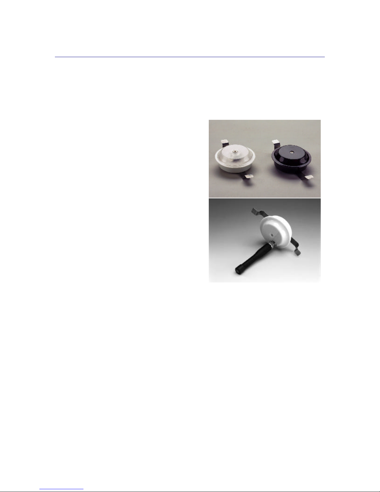
2.1 Readers
Readers receive signals from tags and convert them into electrical signals. There are two reader types,
Infrared (IR) readers and Radio Frequency (RF) readers.
2.1.1 IR Reader
• Required for systems using Versus Technology
active infrared tags.
• Receives IR signals from IR and IR/RF tags.
• Converts IR signals into electrical signals.
• 360 degree horizontal coverage.
• 180 degree hemispherical vertical coverage.
2.1.2 RF Reader
• Required for systems using Versus Technology
active radio frequency tags.
• Operates at 433.9 MHz receive frequency.
• Receives RF signals from RF and IR/RF tags.
• Converts RF signals into electrical signals.
• 50 feet read range.
2.2 Tags
Tags are worn by personnel or attached to equipment. Tags send IR (infrared), RF (radio frequency),
or both IR and RF signals to the readers. This signal contains the “signature” that identifies the tag.
Motion, timing, battery state, and auxiliary information are all included in the signal.
Warning! A low battery can affect system performance. Change low batteries at first
indication.
2.2.1 A Discussion about Active Tags
Most Versus Technology tags are “active”, meaning they contain a battery and they transmit their
signature or ID number at regular intervals. For example, the Versus Infrared “Locator” tag transmits
its ID every 3.5 seconds when the tag is in motion. If the tagged item remains motionless for a period,
the tag will reduce its transmission rate to every 2.5 minutes. This is to conserve power consumption,
which extends the life of the battery, and to reduce unnecessary transmission signals.
3 Eagle Eye Direct
 Loading...