

Versum Materials Chemguard Genlll 050 Installation, Operation & Maintenance Manual

Installation / Operation / Maintenance
Manual
CHEMGUARD GenIII 050
Chemical Equipment
Manual Part Number: 477444
Edition: Rev-0
© Versum Materials US, LLC. as of the revision and date shown. All rights reserved.
Confidential and Proprietary Data
VersumMaterialsConfidential

The information and data contained herein are proprietary to Versum Materials, Inc. and
are not to be copied, reproduced, duplicated, or disclosed to others, in whole or in part,
without prior written consent of Versum Materials, Inc. The information and data
should be available only to those with a need to know. Versum Materials, Inc. makes no
representation that the information and data is appropriate for the recipient, and each
recipient needs to independently evaluate the appropriateness of the information and
data for its use.
This Installation and Operation Manual is subject to change without notification. For
current technical information please call Product Support at (866)624-7677 from
continental U.S., or write Versum Materials, Inc., 1919 Vultee Street, Allentown, PA
18103, attention: Product Support.
Printed in the U.S.A.
_______________________________________________________________________________________________________________
mnl000621 Revision 0 06/27/2019
© Versum Materials US, LLC. as of the revision and date shown. All rights reserved.
VersumMaterialsConfidential
Page C - 2
Confidential and Proprietary Data

WARRANTY
Versum Materials, Inc. (hereinafter referred to as "Versum Materials") warrants that:
(A) Each new Versum Materials Delivery System is free from defects in material and
workmanship under normal use and service for a period of one year from the date of
delivery by Versum Materials to the first purchaser.
(B) Each new accessory is free from defects in material and workmanship under
normal use and service for a period of one (1) year from the date of delivery by Versum
Materials to the first purchaser.
If any product requires service during the applicable warranty period, the purchaser
should communicate directly with Versum Materials to determine appropriate repair.
Repair or replacement will be carried out at Versum Materials expense subject to the
terms of this warranty. It is the responsibility of the customer to perform routine
maintenance and periodic calibration.
In no event shall Versum Materials be liable for any incidental, indirect or consequential
damages in connection with the purchase or use of any Versum Materials product. This
warranty shall not apply to, and Versum Materials shall not be responsible for, any loss
arising in connection with the purchase or use of any Versum Materials product which
has been repaired by anyone other than an authorized Versum Materials service
representative or altered in any way so as, in Versum Materials judgment, to affect its
stability or reliability, or which has been subject to misuse or negligence or accident, or
which has the unit or lot number altered, effaced or removed, or which has been used
otherwise than in accordance with the instructions furnished by Versum Materials.
This warranty is in lieu of all other warranties, express or implied, and all other
obligations or liabilities on Versum Materials part, and Versum Materials neither
assumes nor authorizes any representative or other person to assume for it any other
liability in connection with the sale of Versum Materials equipment.
VERSUM MATERIALS DISCLAIMS ALL OTHER WARRANTIES, EXPRESS
OR IMPLIED, INCLUDING ANY WARRANTY OF MERCHANTABILITY OR
OF FITNESS FOR A PARTICULAR PURPOSE OR APPLICATION.
Address:
Versum Materials, Inc.
1919 Vultee Street
Allentown, PA 18103, U.S.A
_______________________________________________________________________________________________________________
mnl000621 Revision 0 06/27/2019
© Versum Materials US, LLC. as of the revision and date shown. All rights reserved.
VersumMaterialsConfidential
Page C - 3
Confidential and Proprietary Data

Revision Control Summary
Chapter Revision File Name
Chapter 1 – Delivery and Inspection
Rev-0 MNL000622.doc
Initial Release.
Chapter 2 – Site Preparation
Rev-0 MNL000623.doc
Initial Release.
Chapter 3 – Installation
Rev-0 MNL000624.doc
Initial Release.
Chapter 4 – 38 Liter Bubbler Installation
Rev-0 MNL000625.doc
Initial Release.
Chapter 5 – Features and Components
Rev-0 MNL000626.doc
Initial Release.
Chapter 6 – System Operation
Rev-0 MNL000627.doc
Initial Release.
Chapter 7 – Maintenance and Calibration Procedure
Rev-0 MNL000628.doc
Initial Release.
Addendum A – LPE 14 Liter Bubbler Change Procedure
Rev-0 MNL000629.doc
Initial Release.
Addendum B – Gas Filter Setup
Rev-2 MNL000108.doc
AP to Versum update.
Appendix F – Gas Sensor Instruction
Rev-2 MNL000112.doc
AP to Versum update.
_______________________________________________________________________________________________________________
mnl000621 Revision 0 06/27/2019
© Versum Materials US, LLC. as of the revision and date shown. All rights reserved.
VersumMaterialsConfidential
Page C - 4
Confidential and Proprietary Data

TABLE OF CONTENTS
Chapter 1 Delivery and Inspection
Section 1 Delivery .......................................................................... 1-2
Section 2 Inspection ....................................................................... 1-2
Chapter 2 Site Preparation
Section 1 Facility Preparation ........................................................ 2-2
Section 2 Facility Requirements .................................................... 2-4
Section 3 Tag and Lockout Routine ................................................ 2-16
Section 4 Spill Cleanup Routine ..................................................... 2-17
Chapter 3 Installation
Section 1 Introduction ..................................................................... 3-2
Section 2 Reference Documents ..................................................... 3-2
Section 3 Installation ....................................................................... 3-3
Section 4 Installing the ChemGuard® CG050 Cabinet ................... 3-4
Section 5 Connecting ChemGuard® Gas Lines ............................... 3-11
Section 6 Chemical Delivery Line Requirements ........................... 3-11
Section 7 Installing ChemGuard® Bulk Scale ................................. 3-16
Section 8 Communications ............................................................. 3-17
Section 9 Start-up and Initialization ................................................ 3-23
Section 10 System Configuration ...................................................... 3-28
Section 11 Manual Mode .................................................................. 3-30
Section 12 Regulator Adjustment ..................................................... 3-33
Section 13 Finishing the ChemGuard® Installation .......................... 3-34
Chapter 4 38 Liter Bubbler Installation
Section 1 38 Liter Bubbler Installation ........................................... 4-2
Section 2 Bubbler Valves ............................................................... 4-2
Section 3 Installation of the Bubbler and Valves ............................ 4-3
Section 4 Bubbler and System Leak Test - Setup ........................... 4-5
Section 5 Leak Test – Main Manifold -> Pressure Decay .............. 4-6
Section 6 Leak Test – Vapor Out -> Pressure Decay ...................... 4-6
Section 7 Leak Test – Sample Out/Purge Line -> Pressure Decay . 4-7
Section 8 Leak Test – 38L Bubbler/Outer Cooling Jacket -> Pressure Decay.4-7
Section 9 Leak Test – External Refill Line -> Pressure Decay ....... 4-8
Section 10 System Purge ................................................................... 4-9
Section 11 Install Bubbler Chiller Connections ................................ 4-9
Section 12 Entering Bubbler Liquid Weight ..................................... 4-10
Chapter 5 ChemGuard
Section 1 Overview ........................................................................ 5-2
Section 2 Component Description .................................................. 5-4
Section 3 Available Options ............................................................ 5-14
®
GEN III Features and Components
_______________________________________________________________________________________________________________
mnl000621 Revision 0 06/27/2019
© Versum Materials US, LLC. as of the revision and date shown. All rights reserved.
VersumMaterialsConfidential
Page C - 5
Confidential and Proprietary Data

Chapter 6 System Operation
Section 1 Theory of Operation ........................................................ 6-2
Section 2 Description of Menu and Operations .............................. 6-4
Section 3 Operating Menu .............................................................. 6-5
Section 4 Alarm Types .................................................................... 6-19
Chapter 7 Maintenance & Calibration Procedures
Section 1 Introduction ..................................................................... 7-2
Section 2 Calibration and Testing ................................................... 7-2
Addendum A LPE 14 Liter Bubbler Change
Section 1 Safety Notes .................................................................... A-2
Section 2 Removing and Replacing the Bubbler ............................ A-3
Section 3 Change BULK Bubbler Operation .................................. A-4
Addendum B Gas Filter Setup
Appendix F Gas Sensor Instruction
_______________________________________________________________________________________________________________
mnl000621 Revision 0 06/27/2019
© Versum Materials US, LLC. as of the revision and date shown. All rights reserved.
VersumMaterialsConfidential
Page C - 6
Confidential and Proprietary Data

Chapter 1 - Delivery and Inspection
_______________________________________________________________________________________________________________
MNL000622.doc Revision 0 6/17/2019
Chemical Equipment
© Versum Materials US, LLC. as of the revision and date shown. All rights reserved.
Confidential and Proprietary Data
Page 1 - 1
Versum Materials Confidential
Chapter 1
Delivery and Inspection
Section 1 Delivery
Section 2 Inspection

Chapter 1 - Delivery and Inspection
_______________________________________________________________________________________________________________
MNL000622.doc Revision 0 6/17/2019
Chemical Equipment
© Versum Materials US, LLC. as of the revision and date shown. All rights reserved.
Confidential and Proprietary Data
Page 1 - 2
Versum Materials Confidential
Chapter 1: Delivery and Inspection
1.1 Delivery
The ChemGuard® Gen III may be shipped in multiple packing boxes. The packing slip on the
outside of one of the cartons indicates the number of items in the order. A separate Shipping
Identification Sheet (SIS), or packing checklist, included with the manuals, identifies all
components in the shipment. Before unpacking, make sure your order includes the correct
number of packages.
This shipment includes one empty bubbler chemical container. You will need to order a
container or containers containing chemical. The contents of the packing boxes are:
• The ChemGuard
®
Gen III Cabinet
• One (1) empty bubbler chemical container
• Start-up kit (See Packing Checklist included with shipment)
• Shipping Identification Sheet (packing checklist)
• ChemGuard® Gen III Quality Inspection Records
NOTE: Save all cartons (along with foam supports and padding) for re-use in
case unit must be returned to Versum Materials, Inc.
1.2 Inspection
Be sure each item on the packing checklist is included in the shipment. Notify Versum
Materials, Inc. within 30 days if anything is missing. After 30 days, it is the customer’s
responsibility to purchase missing or damaged parts.
1. Verify that the part numbers on the items are the same as specified on the Shipping
Identification Sheet (SIS).
2. Keep the packing checklist for use in any future communication with Versum Materials,
Inc. Customer Service.

Chapter 2 - Site Preparation
MNL000623.doc Revision 0
06/25/2019
Chemical Equipment
© Versum Materials US, LLC. as of the revision and date shown. All rights reserved.
Confidential and Proprietary Data
Page 2 - 1
Versum Materials Confidential
Chapter 2
Site Preparation
Section 1 Facility Preparation
Section 2 Facility Requirements
Section 3 Tag and Lockout Routine
Section 4 Spill Cleanup Routine

Chapter 2 - Site Preparation
MNL000623.doc Revision 0
06/25/2019
Chemical Equipment
© Versum Materials US, LLC. as of the revision and date shown. All rights reserved.
Confidential and Proprietary Data
Page 2 - 2
Versum Materials Confidential
Chapter 2: Site Preparation
This chapter describes the space and clearances required to install ChemGuard®
CG050 systems along with specifications for power, gas, vacuum, cabinet
exhaust, reservoir vent and chemical delivery line.
Before the ChemGuard® CG050 unit can be installed, the customer must prepare
the location site as detailed in the following section to provide sufficient space and
clearance around the unit. Ensure the AC power, vacuum and gas sources are
available in close proximity to the unit. Please read the information in this chapter
carefully to avoid problems later.
The user of this product is responsible for compliance with all applicable
environmental laws and regulations including local governing agencies and
state/local laws (i.e., Clean Water Act, Clean Air Act, and Hazardous Waste
Laws).
The information and data contained herein are proprietary to Versum Materials,
Inc. and are not to be copied, reproduced, duplicated, or disclosed to others, in
whole or in part, without prior written consent of Versum Materials, Inc. The
information and data should be available only to those with a need to know.
Versum Materials, Inc. makes no representation that the information and data is
appropriate for the recipient, and each recipient needs to independently evaluate
the appropriateness of the information and data for its use. This information and
data were originally written in English.
ChemGuard® CG050 hazard location groups include Class I, Division II Groups B,
C, D (United States) and Group 2, Category 3 ATEX (Europe)
If the equipment is used in a manner not specified by the manufacturer, the
protection provided by the equipment may be impaired.
2.1 Facility Preparation
Determine a suitable location for ChemGuard® CG050 cabinet. Versum Materials,
Inc. recommends installing the cabinet in close proximity to:
• Your AC power source
• Your vacuum supply
• Your helium push gas and nitrogen purge gas supplies
Chapter 2 - Site Preparation
MNL000623.doc Revision 0
06/25/2019
Chemical Equipment
© Versum Materials US, LLC. as of the revision and date shown. All rights reserved.
Confidential and Proprietary Data
Page 2 - 3
Versum Materials Confidential
Ensure that there is ample space to allow the cabinet doors to open completely and that there is
proper clearance around the unit. (See Table 2-1 for required cabinet clearances.) If an optional
fire extinguisher is installed, additional clearance may be required.
Table 2-1: Cabinet Clearances
PLACEMENT
CLEARANCES
Height
87 in. (2.209 meters)
Width
18 in. (457 mm)
Depth
Door open: 37 in. (940 mm)
Door closed: 21 in. (533 mm)
2.1.1 Bolt-Down and Ground Cabinet Requirements
Set the ChemGuard® CG050 cabinet over the bolt-down points and attach
securely. Verify ChemGuard® CG050 is in a level location where it can be
serviced easily, and is out of the main thoroughfare.
Per current United States UBC and SEMI S2-STANDARD requirements, floor
bolts must be at least Grade 5 (metric Grade 8.8), at a recommended minimum
length of 2.5 in. (6.35 cm).
1. Place the cabinet at the designated location.
2. Verify that there is enough room around the cabinet to fully open the door, or
perform maintenance tasks.
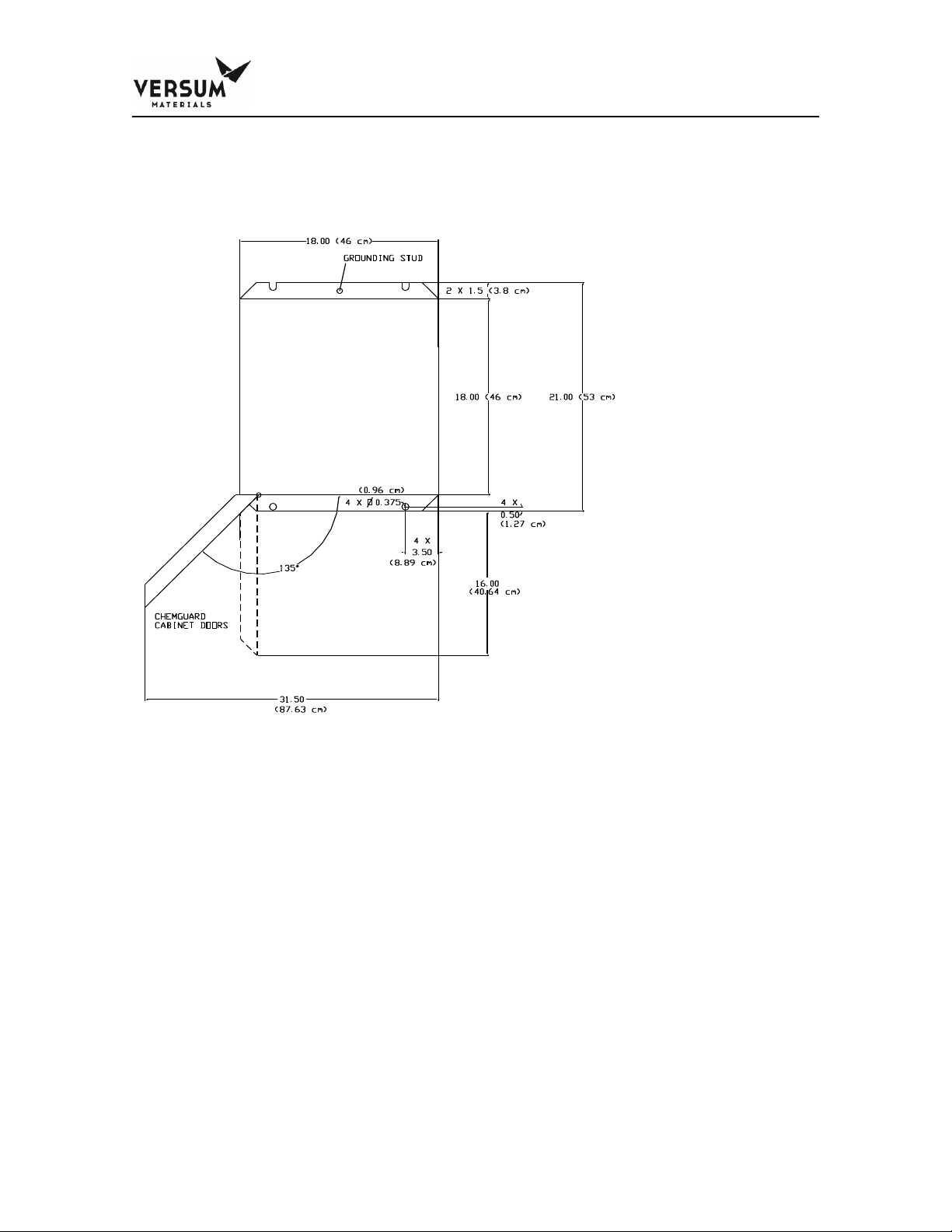
3. The ChemGuard® CG050 must be grounded in accordance with Article 250 Grounding, The National Electrical Code 2003. Refer to Figure 2-1 for the
location of the grounding lug. Versum Materials, Inc. recommends a ground
resistance of <1.0 Ohms.
Chapter 2 - Site Preparation
MNL000623.doc Revision 0
06/25/2019
Chemical Equipment
© Versum Materials US, LLC. as of the revision and date shown. All rights reserved.
Confidential and Proprietary Data
Page 2 - 4
Versum Materials Confidential
Figure 2-1:
Earthquake Bolt-Down Pattern with Front Door Clearances
2.2 Facility Requirements
When selecting a location for the unit, ensure that the following facilities are
available to make connections on top of the cabinet.
• Environmental
• Electrical
• Supply gases
• Venturi Vacuum
Supply
• Exhaust and Vent
• Chemical Delivery Line
• Bulk Chemical Refill Line (from
BCD200, CG010 or CG310)
• Chemical Outlet
Chapter 2 - Site Preparation
_______________________________________________________________________________________________________________
MNL000623.doc Revision 0 06/25/2019
Chemical Equipment
© Versum Materials US, LLC. as of the revision and date shown. All rights reserved.
Confidential and Proprietary Data
Page 2 - 5
Versum Materials Confidential
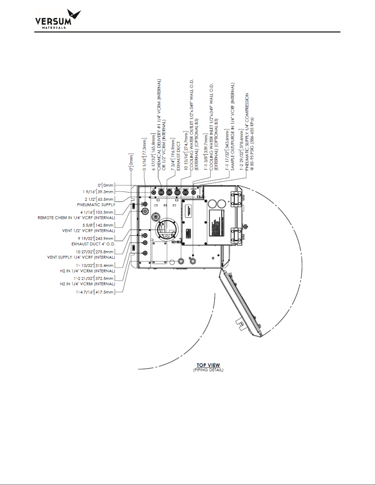
Figure 2-2:
CG050 GEN III Cabinet Connections, Top View
Chapter 2 - Site Preparation
_______________________________________________________________________________________________________________
MNL000623.doc Revision 0 06/25/2019
Chemical Equipment
© Versum Materials US, LLC. as of the revision and date shown. All rights reserved.
Confidential and Proprietary Data
Page 2 - 6
Versum Materials Confidential
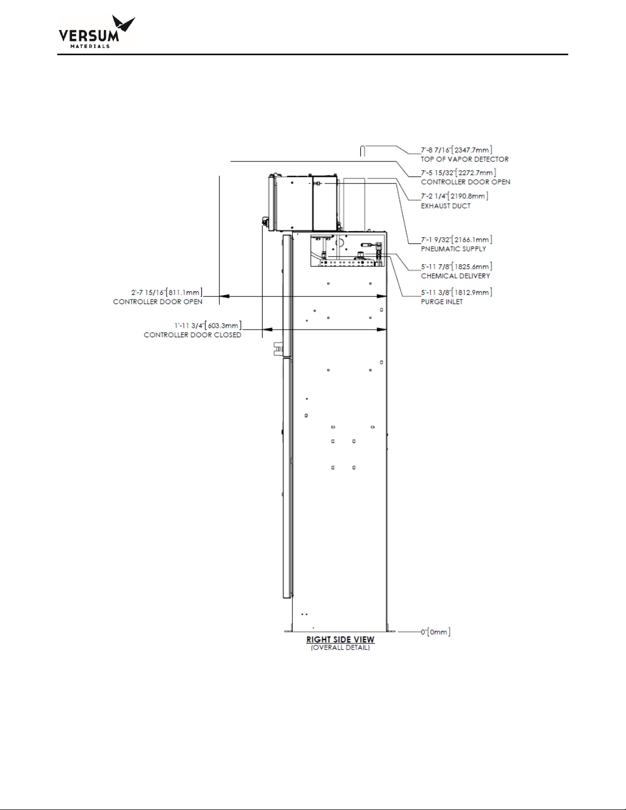
Figure 2-3:
CG050 GEN III Cabinet Connections, Right Side View
Chapter 2 - Site Preparation
_______________________________________________________________________________________________________________
MNL000623.doc Revision 0 06/25/2019
Chemical Equipment
© Versum Materials US, LLC. as of the revision and date shown. All rights reserved.
Confidential and Proprietary Data
Page 2 - 7
Versum Materials Confidential
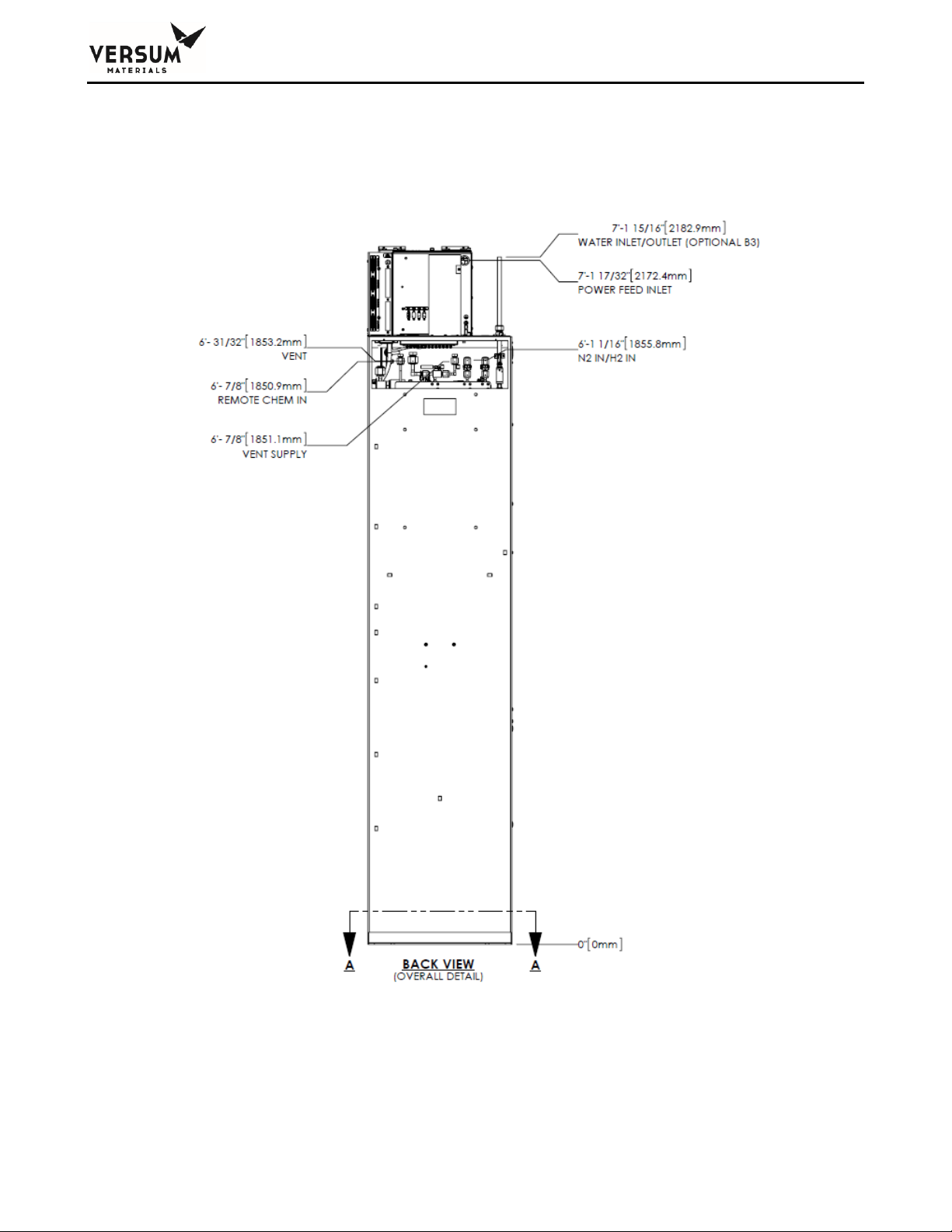
Figure 2-4:
CG050 GEN III Cabinet Connections, Back View
Chapter 2 - Site Preparation
_______________________________________________________________________________________________________________
MNL000623.doc Revision 0 06/25/2019
Chemical Equipment
© Versum Materials US, LLC. as of the revision and date shown. All rights reserved.
Confidential and Proprietary Data
Page 2 - 8
Versum Materials Confidential
2.2.1 Environmental Requirements
The customer is responsible for compliance with applicable environmental laws and
regulations, including local governing agencies and state/local laws (i.e. Clean Water Act,
Clean Air Act, Hazardous Waste Laws).
Table 2-2: Environmental Requirements
CONDITION
RANGE
Environmental
Operating Temperature: 0ºC to 40ºC
Humidity: 5% to 95% RH, non-condensing
Temperature must be compatible with chemical used.
Lighting
Minimum of 300 lux of illumination
2.2.2 Electrical Requirements
Versum Materials, Inc. recommends connection to an Uninterrupted Power Supply (UPS) and
a Ground-Fault circuit Interrupter (GFCI). Versum Materials, Inc. recommends that customer
electrically ground the ChemGuard® CG050 cabinet and plumbing.
SEMI S2 requires a lockout type circuit breaker setup for the AC power. OSHA standards
require customer to install lockout-type, 10K interrupt current (AIC) circuit breaker for AC
power. Recommend placement of breaker 1 – 10 meters (3 – 32 ft.) from BCD.
Per SEMI S2 requirements, all electrical work for ChemGuard® CG050 GEN III is Type 1 and
Type 2.
Type 1 = Equipment fully de-energized
Type 2 = Equipment is energized
S2 requires a lockout type circuit breaker setup for the AC power.
WARNING:
Live circuits are covered and/or insulated, Lockout / Tagout is required while work is performed at a remote
location to preclude accidental shock.
Chapter 2 - Site Preparation
_______________________________________________________________________________________________________________
MNL000623.doc Revision 0 06/25/2019
Chemical Equipment
© Versum Materials US, LLC. as of the revision and date shown. All rights reserved.
Confidential and Proprietary Data
Page 2 - 9
Versum Materials Confidential
Table 2-3: Electrical Requirements
CONDITION
RANGE
AC Power
100 - 240 VAC, 100 W @ 50 - 60 Hz; Single-Phase, 3 wires;
Neutral solidly grounded
125 VAC, 1000 W @ 50 - 60 Hz; Single-Phase, 3 wires;
Neutral solidly grounded, with Degasser Vacuum Pump option
2.2.3 Process Tool Interface and Life Safety Interconnect
The external interface cable hookup between ChemGuard® CG050 product line and OEM
Tool or Site Area Monitor System is customer responsibility. It is recommended to use multiconductors shield cable with twisted pairs, 22-20 AWG, 7x30 stranded, rated 300-600V RMS,
minimum 7-10 pairs (14-20 conductors) per interface.
Table 2-4: Digital I/O
DIGITAL INPUTS
DIGITAL OUTPUTS
Input current, On
4.07 mA min.5.3 mA
max.
Resistive
Load
1.0 A @ 30 VDC,
0.5 A @ 120 VDC
Input voltage, On
24.0 VDC ±20%
Switching
Power
30 W max.
Input current, Off
100 µA max.
Contact
material
Silver alloy, goldetched clad
Input voltage, Off
1.0 VDC max.
Protection
36V Zener
2.2.4 Supply Gases
The customer is required to supply all gases, filters, check-valves, and regulators. Ensure
that the required gases are available in close proximity to the ChemGuard® CG050
installation site. (see Chapter 3 for further details).
Ensure there are shutoff valves and filters for gas lines feeding the ChemGuard® CG050.
Ensure the correct gases are used for the process chemical and the properties of the gas are
correct for the process chemical (i.e. dry N2). (See Table 2-5).
To reduce the potential of flow fluctuations, the end-user must properly design the facilities
for the ChemGuard® CG050, i.e. incoming gas supplies and chemical delivery line layouts
with adequate line size, vertical rise, horizontal length between the ChemGuard® CG050 and
the process tool(s).
Chapter 2 - Site Preparation
_______________________________________________________________________________________________________________
MNL000623.doc Revision 0 06/25/2019
Chemical Equipment
© Versum Materials US, LLC. as of the revision and date shown. All rights reserved.
Confidential and Proprietary Data
Page 2 - 10
Versum Materials Confidential
To avoid potential process failures here are some guidelines the end users should consider
when facilitate ChemGuard® CG050 cabinets at central location.
• ChemGuard® CG050 cabinets centrally located and within close proximity to the
process tool (s) to minimize the vertical and horizontal length of the chemical delivery
lines.
• The incoming main gas supply to multiple ChemGuard® CG050 cabinets should be
properly sized to provide adequate pressure and flow before branching out to multiple
ChemGuard® CG050 cabinet connection points.
• After the main gas supply has been branched off to the individual ChemGuard®
CG050 cabinets, Individual gas supply lines are equipped with individual regulators,
check valves and isolation valves which have been properly sized to meet the
pressure and flow requirements of the process tool (s).
A gas filter is required on the houseline supplying the ChemGuard® CG050 push gas.
Failure to install a filter will void regulator and valve warranty if failed component found to
have particles embedded on the seat. See Addendum B for recommended setup.
Minimum filter specifications:
• Filter = 0.003 micron.
• Flow = 50 slpm.
• Material = Electropolished 316L Stainless Steel.
• Membrane = 316L Stainless Steel or PTFE.
• Leak Tested = 100% Helium leak tested to 5x10⁻⁹ atm cc/sec (3.8x10⁻⁹ Torr L/sec).
WARNING:
DO NOT deliver process/purge gases from a high pressure gas cylinder source. The supply gases must be
delivered from the house line gas source regulated to no more than 120 psig with flow not greater than
250 slpm.
A pneumatic supply of inert gas without oxygen is recommended for the controller. It is
strongly advised to not use clean dry air for pneumatic supply. The pneumatic supply may be
shared in the controller between the pneumatic solenoids and the enclosure
inerting/pressurizing service (Z-purge). Based on results from DC power harness testing,
clean dry air may promote the corrosion of electrical connectors for interconnecting power
Chapter 2 - Site Preparation
_______________________________________________________________________________________________________________
MNL000623.doc Revision 0 06/25/2019
Chemical Equipment
© Versum Materials US, LLC. as of the revision and date shown. All rights reserved.
Confidential and Proprietary Data
Page 2 - 11
Versum Materials Confidential
cables. The presence of oxygen enhances the corrosion effect and may result in deterioration
of controller performance.
Table 2-5: Supply Gases
H2 IN:
Process Supply
Gas
Hydrogen gas is Ultra High Pure semiconductor-grade recommended. Water
content < 10 ppb and O2 content < 2ppm.
Recommended to use Inert Gas Purifier model # SS2500KFI4RR or equivalent.
Required to install a 0.003 micron gas filter.
Regulated to 620 70 kPa (90 10 psig, 105 psiA)
Cabinet 6.35 mm ( ¼ in.) male VCR connection
Connects to H2 IN port (See Figure 2-2)
For moisture sensitive chemicals, gas requirements are as follows:
Recommended the Water content < 10 ppb and O2 content < 2ppm.
The customer is required to supply all gases with shut-off valves, regulators,
check-valves, filters and/or gas purifier in-line feeding the ChemGuard. Ensure
the required gases are available in close proximity to the ChemGuard installation
site.
WARNING: DO NOT connect high pressure gas cylinder directly to the cabinet
process/purge gas ports.
N2 IN:
Process Purge
Supply Gas
Nitrogen gas is Ultra High Pure semiconductor-grade recommended. Water
content < 10 ppb and O2 content < 2ppm.
Recommended to use Inert Gas Purifier model # SS2500KFI4RR or equivalent.
Required to install a 0.003 micron gas filter.
Install regulator at N2 IN supply port and regulate to 620 70 kPa (90 10 psig,
105 psiA)
Cabinet 6.35 mm ( ¼ in.) male VCR connection
Connects to N2 IN port (See Figure 2-2)
For moisture sensitive chemicals, gas requirements are as follows:
Recommended the Water content < 10 ppb and O2 content < 2ppm.
The customer is required to supply all gases with shut-off valves, regulators,
check-valves, filters and/or gas purifier in-line feeding the ChemGuard. Ensure
the required gases are available in close proximity to the ChemGuard installation
site.
WARNING: DO NOT connect high pressure gas cylinder directly to the cabinet
process/purge gas ports.
80 PSI 60 SLPM:
Venturi Vacuum
Supply Gas
Recommended teeing off the N2 Process Purge Gas Supply, see specifications
above
Install regulator at 80 PSI 60 SLPM supply port and regulate to 551 kPa (80 psig,
95 psiA) at 60 liters per minute
Cabinet 6.35 mm ( ¼ in.) female VCR connection
Connect to 80 PSI 60 SLPM port (See Figure 2-2)
NOTE: N2 @ 551 kPA results in 100 Torr vacuum with a, minimum 9.4 mm
Chapter 2 - Site Preparation
_______________________________________________________________________________________________________________
MNL000623.doc Revision 0 06/25/2019
Chemical Equipment
© Versum Materials US, LLC. as of the revision and date shown. All rights reserved.
Confidential and Proprietary Data
Page 2 - 12
Versum Materials Confidential
(3/8 in.) vent line
The customer is required to supply all gases with shut-off valves, regulators,
check-valves, filters and/or gas purifier in-line feeding the ChemGuard. Ensure
the required gases are available in close proximity to the ChemGuard installation
site.
SAMPLE
OUT/PURGE IN:
Purge Gas for
Outlet Manifold
Recommended teeing off the N2 Process Purge Gas Supply, see specifications
above
Install regulator at SAMPLE OUT/PURGE IN port and regulate to 140-275 kPa
(20-40 psig)
Cabinet 6.35 mm (¼ in.) female VCR connection
Connects to SAMPLE OUT/PURGE IN port (See Figure 2-2)
The customer is required to supply all gases with shut-off valves, regulators,
check-valves, filters and/or gas purifier in-line feeding the ChemGuard. Ensure
the required gases are available in close proximity to the ChemGuard installation
site.
NOTE: The Output Manifold allows the cabinet to feed the gas mixture to the
process tool as well as a sample/purge IN port simultaneously. Manual
sample/purge port is also available. The house line can be plumb and ready to
use by opening either of the manual valves
PNEUMATIC
SUPPLY
Nitrogen gas is semiconductor-grade or better is recommended.
Regulated to 620 70 kPa (90 10 psig)
Cabinet 6.35 mm ( ¼ in.) Swagelok connection
Connects to PNEUMATIC port, coarse filter recommended (See Figure 3-2)
A pneumatic supply of inert gas without oxygen is recommended for our
controllers. It is strongly advised to not use clean dry air for pneumatic
supply. The pneumatic supply may be shared in the controller between the
pneumatic solenoids and the enclosure inerting/pressurizing service (Z-purge).
Based on results from DC power harness testing, clean dry air may promote the
corrosion of electrical connectors for interconnecting power cables. The presence
of oxygen enhances the corrosion effect and may result in deterioration of
controller performance.
The customer is required to supply all gases with shut-off valves, regulators,
check-valves, filters and/or gas purifier in-line feeding the ChemGuard. Ensure
the required gases are available in close proximity to the ChemGuard installation
site.
Chapter 2 - Site Preparation
_______________________________________________________________________________________________________________
MNL000623.doc Revision 0 06/25/2019
Chemical Equipment
© Versum Materials US, LLC. as of the revision and date shown. All rights reserved.
Confidential and Proprietary Data
Page 2 - 13
Versum Materials Confidential
2.2.5 Exhaust and Vent Requirements
NOTE: Vent line can be installed to the facility exhaust if exhaust is connected to the
appropriate abatement system for the chemical used. Versum Materials, Inc.
recommends facility exhaust controls/abatement in lieu of on-board (localized)
controls/abatement system.
The reservoir vent function allows removal of pressure from the Reservoir Container. The
vent should be connected to the appropriate abatement system for chemical used. Ventilation
measurements should be made at a distance of four (4) duct diameters from the cabinet.
Versum Materials, Inc. recommends that ducting be made from zinc-plated steel, with
operation at static pressure of 0.7 in. of water.
NOTE: If your installation has the combustible, lower explosion limit (LEL) vapor-detector
option, see facilities requirements and Appendix F.
WARNING: Venturi exhaust
contains chemical vapor. Exhaust
must be connected to the
appropriate abatement system for
chemical used.
WARNUNG: Die Abgase
enthalten chemische Dämpfe.
Pumpenabgase müssen über ein
für das jeweilig Chemikal
geeignetes Abgassystem
abgeführt warden.
AVERTISSEMENT: Le tuyau
d’échappement de la pompe
contient des vapeurs chimiques.
Le tuyau d’échappement doit être
connecté à un système de
réduction adéquat au produit
chimique utilize
Chapter 2 - Site Preparation
_______________________________________________________________________________________________________________
MNL000623.doc Revision 0 06/25/2019
Chemical Equipment
© Versum Materials US, LLC. as of the revision and date shown. All rights reserved.
Confidential and Proprietary Data
Page 2 - 14
Versum Materials Confidential
Table 2-6: Exhaust and Vent Requirements
EXHAUST
101.6 mm (4 in.) diameter circular duct
Cabinet Exhaust Flow/Pressure Set Point: 850 Liter/minute (30 CFM) minimum
recommended
Connect to the appropriate abatement system for chemical used.
It is recommended to install the Exhaust line perpendicular and/or above the main
abatement duct. DO NOT ENTER BELOW THE MAIN ABATEMENT DUCT TO AVOID
LIQUID TRAP
VENT:
Venturi
Vacuum
Exhaust
Connect to the appropriate abatement system for chemical used
Cabinet 12.70 mm (½ in.) female VCR connection
Connects to VENT port (See Figure 2-2)
Vent line is to be connected directly to the main abatement duct and not the
ChemGuard exhaust duct.
It is recommended to install the Vent line perpendicular and/or above the main
abatement duct. DO NOT ENTER BELOW THE MAIN ABATEMENT DUCT TO AVOID
LIQUID TRAP
2.2.6 Chemical Vapor Delivery Line Requirements
The end user must have knowledge of process flow requirements, prepare flow calculations
for sufficient flow and have a carefully designed layout plan for the installation of the
ChemGuard® CG050 cabinet – preferably at a central location where the facilities will meet the
process tool requirements. Proper facilitation and installation will reduce and avoid potential
failures, tool downtime and rework costs.
Chemical delivery line to each process tool(s) should be designed and install with minimum
distance in vertical rise (height) and horizontal length between ChemGuard® CG050 cabinet
and the process tool (s) to meet process operating pressure and flow rate required of the
process tool (s). Refer to Chemical Delivery Line Requirements Postion paper _ DOC000140
NOTE: All chemical delivery line requirements are the customer’s responsibility. Versum
Materials, Inc. recommends installing coaxial Chemical Delivery Lines. Versum
Materials, Inc. recommends customer install a lockable shutoff valve on the
chemical delivery line, to comply with OSHA lockout/tagout requirements.
The customer provides the chemical delivery line. All bends should meet SEMATECH
standards for bend radius.
The chemical line should be helium leak-checked, purged, cleaned and certified prior to
installing and chemical introduction.
The chemical delivery line is connected to the chemical output manifold and is then directed
to the Process Tool’s chemical input manifold.
Chapter 2 - Site Preparation
_______________________________________________________________________________________________________________
MNL000623.doc Revision 0 06/25/2019
Chemical Equipment
© Versum Materials US, LLC. as of the revision and date shown. All rights reserved.
Confidential and Proprietary Data
Page 2 - 15
Versum Materials Confidential
Table 2-7: Chemical Delivery Line Requirements
CHEMICAL
DELIVERY
#1:
Vapor Flow
out to Tool
6.35 mm (¼ in.) male VCR connection
316L stainless steel, electro-polished line.
Connects to Chem Delivery #1 port (See Figure 2-2)
Bends should meet SEMATECH standards for bend radius. Versum Materials, Inc.
recommends inside electro-polish rating 10RA maximum.
Chemical Line should be Helium leak-checked, purged, and cleaned before installing
ChemGuard.
Optional Outer Coaxial Line (if required by customer or local regulations): 12.7 mm (½
in.) stainless steel.
Optional
Outer Coaxial
Line
Optional Outer Coaxial Line (if required by customer or local regulations): 12.7 mm (½ in.)
stainless steel.
Bends should meet SEMATECH standards for bend radius.
Specification for Outer Lines
• Stainless steel line
• The line should be welded
• Sharp edges should be removed and de-burred at breaks in the line to prevent stainless
steel inner line from being scratched or torn when routing through the outer line.
2.2.7 Installing the Optional Coaxial Chemical Delivery Lines
The Optional Coaxial Chemical Delivery Lines comprised of:
• Outer line, 12.7 mm (1/2 in.) stainless steel line.
• Inner line, 6.35 mm (1/4 in.) stainless steel line.
Specification for outer lines
• Stainless steel line
• The line should be welded
• Sharp edges should be removed and de-burred at breaks in the line to prevent
stainless steel inner line from being scratched or torn when routing through the outer
line.
2.2.8 Chemical Bulk Refill Line (from BCD200, CG010 or CG310)
The chemical refill line is an additional line, routed on top of the ChemGuard® CG050. It
allows the BULK reservoir container to be filled from an external source (i.e., ChemGuard®
BCD200, CG010 or CG310 cabinet).
Chapter 2 - Site Preparation
_______________________________________________________________________________________________________________
MNL000623.doc Revision 0 06/25/2019
Chemical Equipment
© Versum Materials US, LLC. as of the revision and date shown. All rights reserved.
Confidential and Proprietary Data
Page 2 - 16
Versum Materials Confidential
Table 2-8: Chemical Bulk Refill Line Requirements
REMOTE
CHEM IN:
Chemical
Bulk Refill
Line from
the
BCD200,
CG010 or
CG310
6.35 mm (¼ in.) female VCR connection
316L stainless steel, electro-polished line
Connects to REMOTE CHEM IN port (See Figure 2-2)
Bends should meet SEMATECH standards for bend radius. Versum Materials, Inc.
recommends inside electro-polish rating 10RA maximum.
Chemical Refill Line should be Helium leak-checked, purged, and cleaned before
installing ChemGuard.
Optional Outer Coaxial Line (if required by customer or local regulations): 12.7 mm (½
in.) stainless steel.
2.2.9 Sample/Purge Output Manifold
The Output Manifold allows the cabinet to feed the gas mixture to the process tool as well as
a sample/purge port simultaneously. Manual sample/purge port is also available. The house
line can be plumb and ready to use by opening either of the manual valves.
2.2.10 Coolant Supply/Return (optional)
The ChemGuard® CG050 is configured with a standard coolant supply and return lines with
overpressure protection, shutoff, and drain capability built into the cabinet. The temperature
of the bubbler is typically maintained at 18° C.
Table 2-9: Coolant Supply/Return Requirements
COOLANT
SUPPLY /
RETURN
Cabinet 12.70 mm (1/2 in.) Female NPT connection (See Figure 2-2)
Flow: 7.6 liters per minute (2 US gpm)
Pressure: Up to 2.75 barg (40 psig)
2.3 Tag and Lockout Routine
When performing certain maintenance procedures described in this manual, electrical power
to the ChemGuard® CG050 must be de-energized, using site lockout/tag out procedures.
Consult your company’s safety procedures for tagging and lockout instructions to be followed
when performing such maintenance.
It is the customer’s responsibility to ensure compliance with local electrical regulations
external to the equipment.
Chapter 2 - Site Preparation
_______________________________________________________________________________________________________________
MNL000623.doc Revision 0 06/25/2019
Chemical Equipment
© Versum Materials US, LLC. as of the revision and date shown. All rights reserved.
Confidential and Proprietary Data
Page 2 - 17
Versum Materials Confidential
Sequence of Lockout or Tagout System Procedure
1. Notify all affected employees that a lockout or tagout system is going to be utilized and
the reason therefore. The authorized employee shall know the type and magnitude of
energy that the machine or equipment utilizes and shall understand the hazards thereof.
2. If the machine or equipment is operating, shut it down by the normal stopping procedure
(depress stop button, open toggle switch, etc.).
3. Operate the switch, valve, or other energy isolating device(s) so that the equipment is
isolated from its energy source(s). Stored energy (such as that in springs, elevated
machine members, rotating flywheels, hydraulic systems, and air, gas, steam or water
pressure, etc.) must be dissipated or restrained by methods such as repositioning,
blocking, bleeding down, etc. (Type(s) of stored energy methods to dissipate or
restrain).
4. Lockout and/or tagout the energy isolating devices with assigned individual lock(s) or
tag(s) (Method(s) selected, i.e., locks, tags, additional safety measures, etc.)
5. After ensuring that no personnel are exposed, and as a check on having disconnected
the energy sources, operate the push button or other normal operating controls to make
certain the equipment will not operate (Type(s) of equipment checked to ensure
disconnections).
CAUTION
Return operating control(s) to neutral or off position after the test.
6. The equipment is now locked or tagged out.
2.4 Spill Cleanup Routine
In dealing with chemical spills/mitigating releases, always use proper personal protective
equipment, including gloves, face and eye protection, respirators, and protective clothing.
Due to various factors in each spill incident, it has been determined unsafe to provide generic
spill instructions for each type of chemical delivered by ChemGuard® CG050 cabinets. For
example, two spills of the same type of chemical could have two different spill procedures.
Therefore, in the event of a spill, we recommend immediately contacting your chemical
provider for specific chemical spill recommendations and environmental regulatory

Chapter 2 - Site Preparation
_______________________________________________________________________________________________________________
MNL000623.doc Revision 0 06/25/2019
Chemical Equipment
© Versum Materials US, LLC. as of the revision and date shown. All rights reserved.
Confidential and Proprietary Data
Page 2 - 18
Versum Materials Confidential
information. It is the responsibility of the customer to follow their EH&S procedures for
hazardous material cleanup.
In addition, consult your company’s environmental hazard/safety procedures for specific
instructions to be followed in the event of a chemical spill from ChemGuard® CG050 GEN III.

Chapter 3 - Installation
MNL000624.doc Revision 0
06/25/2019
Chemical Equipment
© Versum Materials US, LLC. as of the revision and date shown. All rights reserved.
Confidential and Proprietary Data
Page 3 - 1
Versum Materials Confidential
Chapter 3
Installation
Section 1 Introduction
Section 2 Reference Documents
Section 3 Installation
Section 4 Installing the ChemGuard® CG050 Cabinet
Section 5 Connecting ChemGuard® Gas Lines
Section 6 Chemical Delivery Line Requirements
Section 7 Installing ChemGuard® Bulk Scale
Section 8 Communications
Section 9 Start-Up and Initialization
Section 10 System Configuration
Section 11 Manual Mode
Section 12 Regulator Adjustment
Section 13 Finishing the ChemGuard® Installation

Chapter 3 - Installation
MNL000624.doc Revision 0
06/25/2019
Chemical Equipment
© Versum Materials US, LLC. as of the revision and date shown. All rights reserved.
Confidential and Proprietary Data
Page 3 - 2
Versum Materials Confidential
NOTE: Maintenance personnel shall make use of a step stool or small
ladder to safely access the ChemGuard® GEN III controller. Operating personnel
shall make use of a step stool to access the touch screen monitor as required.
3.1 Introduction
This chapter describes the installation of ChemGuard® CG050 GEN III cabinet.
Because each customer application may vary, these instructions are provided as a
guideline and should not be considered as comprehensive.
Please do not begin installing the ChemGuard® unless trained individuals are
present.
The ChemGuard® CG050 comes pre-calibrated and cabinet-tested. The
ChemGuard® Bulk Scale, dual float spill detector, combustible vapor detector
(option) and UVIR (option) are setup prior to leaving the factory. These items
should not require calibration during installation. Please contact Versum Materials,
Inc. if any of these components do not function properly.
NOTE: When highly flammable chemicals are used and present within
the equipment you must:
• Ensure the all connections made to the cabinet are leak tight.
• Use an inert gas purge to dilute the concentration of highly
flammable vapors in the exhaust header to which the vent
piping is connected.
• Use an inert gas purge to the vacuum pump gas ballast
connection.
3.2 Reference Documents
For Installation and P&ID system drawings, facilities inspection, pre-startup and
commissioning procedure and check-off/sign-off lists refer to;
• SW017054_Installation Drawing
• DOC000191 for the ChemGuard® CG050 GEN III P&ID Drawings
• V-TSA060_ChemGuard® Chemical Fill Matrix

Chapter 3 - Installation
MNL000624.doc Revision 0
06/25/2019
Chemical Equipment
© Versum Materials US, LLC. as of the revision and date shown. All rights reserved.
Confidential and Proprietary Data
Page 3 - 3
Versum Materials Confidential
3.3 Installation
3.3.1 Pre-installation
This chapter describes items that should be identified and resolved prior to
installing ChemGuard®.
The end user must have knowledge of process flow requirements, prepare flow
calculations for sufficient flow and have a carefully designed layout plan for the
installation of the ChemGuard® cabinet – preferably at a central location where
the facilities will meet the process tool requirements. Proper facilitation and
installation will reduce and avoid potential failures, tool downtime and rework
costs.
Chemical delivery line to each process tool(s) should be designed and install with
minimum distance in vertical rise (height) and horizontal length between
ChemGuard® cabinet and the process tool (s) to meet process operating pressure
and flow rate required of the process tool (s).
• The maximum range that a standard ChemGuard® can deliver chemical is
dependent on the chemical and the pressure of the push gas. Contact
Versum Materials, Inc. for any specific delivery requirements beyond 250
meters of horizontal run and 10 meters of vertical run. These distances
could be increased contingent on bends and valve count in the system.
• Install ChemGuard® using the earthquake bolt down points. Verify that the
location has the stability and strength to permit the installation of support
bolts.
• Verify AC power is available for ChemGuard®. Power requirements are
described in Chapter 2.
• Verify all required gases are delivered to an area near the final position of
ChemGuard®. Refer to Chapter 2.
NOTE: All chemical delivery line requirements are the customer’s
responsibility.
• Gases required for ChemGuard® cabinet operation are described in
Chapter 2.
• The ChemGuard® CG050 GEN III cabinet uses venturi vacuum as the
vacuum source so no vacuum pump is required. The vapor pressure of the
chemical used in the ChemGuard® CG050 GEN III cabinet is high enough

Chapter 3 - Installation
MNL000624.doc Revision 0
06/25/2019
Chemical Equipment
© Versum Materials US, LLC. as of the revision and date shown. All rights reserved.
Confidential and Proprietary Data
Page 3 - 4
Versum Materials Confidential
for the venturi vacuum to completely remove all chemical vapors from the
lines during maintenance operations.
• The ChemGuard® requires an exhaust flow of 30 CFM. In addition to
cabinet exhaust, ChemGuard® contains a reservoir vent function that
permits the removal of pressure from the reservoir container. This vent
should be connected to the appropriate abatement system for the chemical
used.
• Coaxial chemical delivery lines are recommended for all process chemicals.
In the event that a leak or rupture occurs in the main delivery line, the liquid
will be contained and be prevented from entering the environment.
• The liquid from any leak will be contained in the ChemGuard® cabinet and
be detected by the spill detector, and container then relieved to prevent any
further spillage.
3.3.2 Available Configurations
The ChemGuard® CG050 GEN III cabinet is used in an epitaxial process.
Hydrogen gas is “bubbled” thru an onboard container typically containing
Trichlorosilane, (TCS) and vapor is then delivered to a Process Tool. This
application is limited to one ChemGuard® per tool or chamber.
3.4 Installing the ChemGuard® CG050 Cabinet
Verify that the cabinet is in a level location with enough clearance around it so that
its doors can be fully opened and so that it can be serviced easily.
Set the ChemGuard® cabinet over the bolt-down points and attach securely.
Per current United States UBC and SEMI requirements, floor bolts must be at
least Grade 5 (metric Grade 8.8), at a recommended minimum length of 2.5 in.
(6.35 cm).
The ChemGuard® must be grounded in accordance with Article 250 - Grounding,
The National Electrical Code 1993. See Figure 2-1 for the location of the
grounding lug. Versum Materials, Inc. recommends a ground resistance of <1
Ohms.
3.4.1 Electrical Connections
Versum Materials, Inc. recommends that the customer electrically ground
ChemGuard® cabinet and plumbing. OSHA standards require customer to install
lockout-type circuit breaker for AC power. Per SEMI S2-93A requirements, all
electrical work for ChemGuard® GEN III is Type 1 and Type 2.
 Loading...