

Versum Materials GASGUARD AP11 BSGS eV Asia, BULKGUARD eV, GASGUARD AP11 BSGS eV, BULKGUARD eV NA/EU Installation, Operation & Maintenance Manual
Page 1

Installation / Operation / Maintenance
Manual
GASGUARD®
AP11 BSGS eV (Asia) /
BULKGUARD® eV (NA/EU)
Manual Part Number: 481319
Edition: Rev-1
© Versum Materials, Inc. as of the revision and date shown. All rights reserved.
Confidential and Proprietary Data
Page 2

The information and data contained herein are proprietary to Versum Materials, Inc. and
are not to be copied, reproduced, duplicated, or disclosed to others, in whole or in part,
without prior written consent of Versum Materials, Inc. The information and data should
be available only to those with a need to know. Versum Materials, Inc. makes no
representation that the information and data is appropriate for the recipient, and each
recipient needs to independently evaluate the appropriateness of the information and data
for its use.
This Installation and Operation Manual is subject to change without notification. For
current technical information please call Product Support at (866)624-7677 from
continental U.S., or write Versum Materials, Inc., 1919 Vultee Street, Allentown, PA
18103, Attention: Product Support.
Printed in the U.S.A.
_______________________________________________________________________________________________________________
MNL000529 Revision 1 03/28/2018
© Versum Materials, Inc. as of the revision and date shown. All rights reserved.
Page C - 2
Confidential and Proprietary Data
Page 3

WARRANTY
Versum Materials, Inc. (hereinafter referred to as "Versum Materials") warrants that:
(A) Each new Versum Materials Delivery System is free from defects in material and
workmanship under normal use and service for a period of one year from the date of
delivery by Versum Materials to the first purchaser.
(B) Each new accessory is free from defects in material and workmanship under
normal use and service for a period of one (1) year from the date of delivery by Versum
Materials to the first purchaser.
If any product requires service during the applicable warranty period, the purchaser
should communicate directly with Versum Materials to determine appropriate repair.
Repair or replacement will be carried out at Versum Materials expense subject to the
terms of this warranty. It is the responsibility of the customer to perform routine
maintenance and periodic calibration.
In no event shall Versum Materials be liable for any incidental, indirect or consequential
damages in connection with the purchase or use of any Versum Materials product. This
warranty shall not apply to, and Versum Materials shall not be responsible for, any loss
arising in connection with the purchase or use of any Versum Materials product which
has been repaired by anyone other than an authorized Versum Materials service
representative or altered in any way so as, in Versum Materials judgment, to affect its
stability or reliability, or which has been subject to misuse or negligence or accident, or
which has the unit or lot number altered, effaced or removed, or which has been used
otherwise than in accordance with the instructions furnished by Versum Materials.
This warranty is in lieu of all other warranties, express or implied, and all other
obligations or liabilities on Versum Materials part, and Versum Materials neither assumes
nor authorizes any representative or other person to assume for it any other liability in
connection with the sale of Versum Materials equipment.
VERSUM MATERIALS DISCLAIMS ALL OTHER WARRANTIES, EXPRESS
OR IMPLIED, INCLUDING ANY WARRANTY OF MERCHANTABILITY OR
OF FITNESS FOR A PARTICULAR PURPOSE OR APPLICATION.
Address:
Versum Materials, Inc.
1919 Vultee Street
Allentown, PA 18103, U.S.A
_______________________________________________________________________________________________________________
MNL000529 Revision 1 03/28/2018
© Versum Materials, Inc. as of the revision and date shown. All rights reserved.
Page C - 3
Confidential and Proprietary Data
Page 4

Revision Control Summary
Chapter Revision File Name
Chapter 1 – Safety Warnings
Rev-7 MNL000127.doc
Label updates
Chapter 2 – Installation
Rev-1 MNL000530.doc
Adding in Process Outlet C and D
Chapter 3 – Module Specifications
Rev-1 MNL000531.doc
Adding in Process Outlet C and D
Chapter 4 – Intentionally Left Blank
Rev-0 MNL000532.doc
Initial Release
Chapter 5 – Intentionally Left Blank
Rev-0 MNL000533.doc
Initial Release
Chapter 6 – Intentionally Left Blank
Rev-0 MNL000534.doc
Initial Release
Chapter 7 – System Description
Rev-1 MNL000535.doc
Adding new optional components
Chapter 8 – Operating Procedures
Rev-1 MNL000536.doc
Software procedure updates
Chapter 9 – Troubleshooting
Rev-0 MNL000537.doc
Initial Release
Chapter 10 – Maintenance
Rev-1 MNL000538.doc
Adding EFS
_______________________________________________________________________________________________________________
MNL000529 Revision 1 03/28/2018
© Versum Materials, Inc. as of the revision and date shown. All rights reserved.
Page C - 4
Confidential and Proprietary Data
Page 5

Appendix A – Installation Drawing Package
Rev-1 MNL000539.doc
Updates for Cyl Flag, alarm matrix, PFD’s
Appendix B – Spare Parts List
Rev-1 MNL000540.doc
Updated Electrical Spares
Appendix C – PED Assessment
Rev-2 MNL000140.doc
Updated Company Name and Logo
Appendix D – Pre-Facilitation Checklist
Rev-0 MNL000541.doc
Initial Release
Appendix E – Startup and Commissioning Checklist
Rev-1 MNL000542.doc
Add EFS
Appendix F – ORI Checklist
Rev-0 MNL000543.doc
Initial Release
Appendix G – UV/IR Detector
Rev-0 MNL000544.doc
Initial Release
Appendix H – USB Barcode Reader
Rev-0 MNL000545.doc
Initial Release
Appendix I – Y-Cylinder Heaters Description
Rev-0 MNL000546.doc
Initial Release
_______________________________________________________________________________________________________________
MNL000529 Revision 1 03/28/2018
© Versum Materials, Inc. as of the revision and date shown. All rights reserved.
Page C - 5
Confidential and Proprietary Data
Page 6

TABLE OF CONTENTS
Chapter 1 Safety Warnings
Section 1 Introduction .................................................................... 1-2
Section 2 Important Safety Warnings ............................................ 1-5
Section 3 Inert Gas Hazards ........................................................... 1-6
Section 4 Pressurized Fluids/Gases ................................................ 1-7
Section 5 Electrical Hazard ............................................................ 1-7
Section 6 Falling Equipment Hazard ............................................. 1-8
Section 7 Gas Cylinder Handling Hazard ...................................... 1-8
Section 8 Pinch Hazard .................................................................. 1-9
Section 9 Personal Protective Equipment ...................................... 1-9
Section 10 Hazard Warnings ............................................................ 1-12
Section 11 Typical Minimal Lockout or Tagout System Procedures 1-22
Section 12 Safety Signs and Labels ................................................. 1-27
Section 13 Equipment Safety Features ............................................ 1-36
Section 14 Safety Literature for Handling and Use of Gas Cylinders 1-38
Section 15 Safety Literature for Handling of Nitrogen Supply ....... 1-38
Chapter 2 Installation
Section 1 Receiving Inspection ...................................................... 2-2
Section 2 Unpacking and Handling ................................................ 2-2
Section 3 Module Installation ........................................................ 2-3
Section 4 Piping Connections ........................................................ 2-8
Section 5 Electrical and Pneumatic Connections ........................... 2-17
Section 6 Explosive Atmosphere (ATEX) Installations… ............. 2-46
Chapter 3 Module Specifications
Chapter 4 Intentionally Left Blank
Chapter 5 Intentionally Left Blank
Chapter 6 Intentionally Left Blank
Chapter 7 System Description
Section 1 System and Components ................................................ 7-2
Section 2 AP11 Controller ............................................................. 7-24
Section 3 Power I/O Enclosures ..................................................... 7-34
_______________________________________________________________________________________________________________
MNL000529 Revision 1 03/28/2018
© Versum Materials, Inc. as of the revision and date shown. All rights reserved.
Page C - 6
Confidential and Proprietary Data
Page 7

Chapter 8 Operating Procedures
Section 1 Emergency Stop ............................................................. 8-2
Section 2 Starting a New System ................................................... 8-3
Section 3 System Shutdown and Startup ....................................... 8-11
Section 4 AP11 Controller Operations ........................................... 8-13
Section 4A Pre-Purge ........................................................................ 8-15
Section 4B Change Source Container ............................................... 8-20
Section 4C Post-Purge ...................................................................... 8-28
Section 4D Process Gas Conditioning .............................................. 8-33
Section 4E Process Gas Flow ........................................................... 8-36
Section 4F Stop and Restart Process Gas Flow ................................ 8-39
Section 4G Idle Mode ....................................................................... 8-45
Section 4H Manual Mode ................................................................. 8-46
Section 4I Tube Switching .............................................................. 8-51
Section 4J Change Y-Container or Drum Source ............................ 8-56
Section 4K Change ISO Container or Tube Trailer Source .............. 8-61
Section 5 AP11 Configuration Menu .............................................. 8-64
Chapter 9 Troubleshooting
Section 1 System Errors ................................................................. 9-2
Section 2 Typical Alarms ............................................................... 9-8
Section 3 J-T Process Heater Reset Procedure .............................. 9-15
Chapter 10 Maintenance
Section 1 Routine Maintenance ..................................................... 10-2
Section 2 Mechanical Integrity ...................................................... 10-8
Section 3 Electrical Maintenance and Test Procedures .................. 10-13
Section 4 Electrical Components Life Expectancy ......................... 10-15
_______________________________________________________________________________________________________________
MNL000529 Revision 1 03/28/2018
© Versum Materials, Inc. as of the revision and date shown. All rights reserved.
Page C - 7
Confidential and Proprietary Data
Page 8

Appendix A Installation Drawing Package
Appendix B Spare Parts List
Section 1 Mechanical Spares ......................................................... APP B-2
Section 2 Electrical Spares ............................................................. APP B-3
Appendix C PED Assessment
Appendix D Pre-Facilitation Checklist
Appendix E Startup and Commissioning Checklist
Appendix F Operational Readiness Inspection Checklist
Appendix G UVIR Detector
Appendix H USB Barcode Reader
Appendix I Y-Cylinder Heaters Description
_______________________________________________________________________________________________________________
MNL000529 Revision 1 03/28/2018
© Versum Materials, Inc. as of the revision and date shown. All rights reserved.
Page C - 8
Confidential and Proprietary Data
Page 9

Chapter 1
Safety Warnings
Section 1 Introduction
Section 2 Important Safety Warnings
Section 3 Inert Gas Hazards
Section 4 Pressurized Fluids / Gases
Section 5 Electrical Hazard
Section 6 Falling Equipment Hazard
Section 7 Gas Cylinder Handling Hazard
Section 8 Pinch Hazard
Section 9 Personal Protective Equipment
Section 10 Hazard Warnings
Section 11 Typical Minimal Lockout or Tagout System
Procedures
Section 12 Safety Signs and Labels
Section 13 Equipment Safety Features
Section 14 Safety Literature for Handling and Use of Gas
Cylinders
Section 15 Safety Literature for Handling and Use of Instrument
Nitrogen Supply
_______________________________________________________________________________________________________________
MNL000127 Revision 7 07/27/2016
Gas Equipment
© Versum Materials, Inc. as of the revision and date shown. All rights reserved.
Page 1 - 1
Confidential and Proprietary Data
Page 10
Chapter 1 - Safety Warnings
Please read the following safety warnings carefully before installing the equipment.
1.1 Introduction
This section is meant to communicate to the user any hazards involved with the equipment.
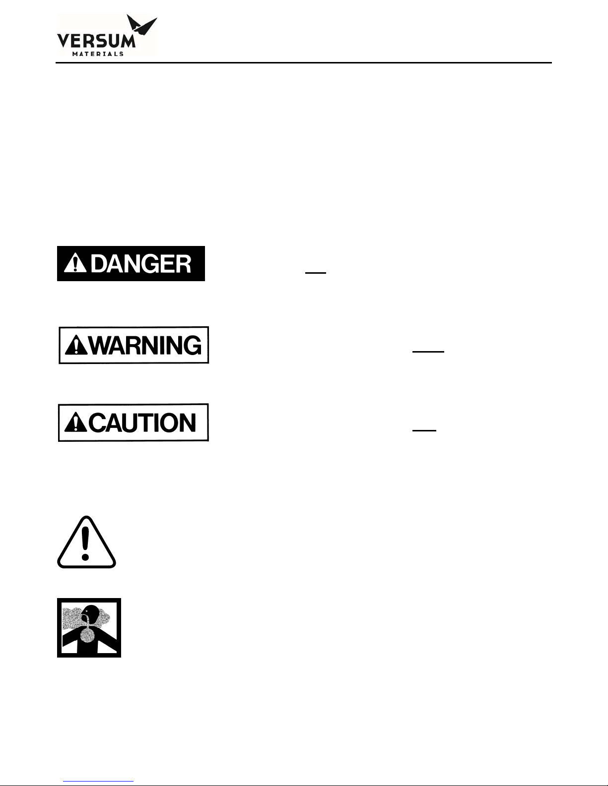
The following paragraphs will define the hazard warnings used and describe the icons found in various
sections of the manual and on the equipment. The hazard warning labels used in the manual will
correlate with those used on the equipment.
1.1.1 Level or Intensity of Hazard
Indicates an immediate hazard, which if
not avoided, will result in death or
serious injury.
Indicates a potentially hazardous
situation, which if not avoided, could
result in death or serious injury.
1.1.2 Hazard Types (Symbols)
This symbol is a safety alert symbol.
This symbol represents asphyxiant, toxic or corrosive
gases. Gases used with the GASGUARD® can cause
personal injury or death.
Indicates a potentially hazardous
situation, which if not avoided, may
result in a minor or moderate injury. It
may also be use to alert against unsafe
practices.
_______________________________________________________________________________________________________________
MNL000127 Revision 8 07/27/2016
Gas Equipment
© Versum Materials, Inc. as of the revision and date shown. All rights reserved.
Page 1 - 2
Confidential and Proprietary Data
Page 11

Chapter 1 - Safety Warnings
This symbol can represent one or more of the following
conditions:
Explosive gases! Gases used with the GASGUARD® can
cause an explosion when combined with air.
The formation for explosive gas mixtures of flammable gas
and air when exposed to an ignition source.
Pyrophoric gases which will ignite spontaneously without
the presence of an ignition source when exposed to air.
Energy release which may result from pneumatic or
hydraulic pressure rapidly escaping from a portion of the
equipment.
This symbol represents flammable gases. Gases used with
the GASGUARD® can cause flammable atmospheres.
This symbol represents PPE (Personal Protective
Equipment). Proper PPE shall be worn when working
with this system.
This symbol represents electrical shock hazard.
This symbol warns of potential strain or injury when
lifting cylinders.
_______________________________________________________________________________________________________________
MNL000127 Revision 8 07/27/2016
Gas Equipment
© Versum Materials, Inc. as of the revision and date shown. All rights reserved.
Page 1 - 3
Confidential and Proprietary Data
Page 12
Chapter 1 - Safety Warnings
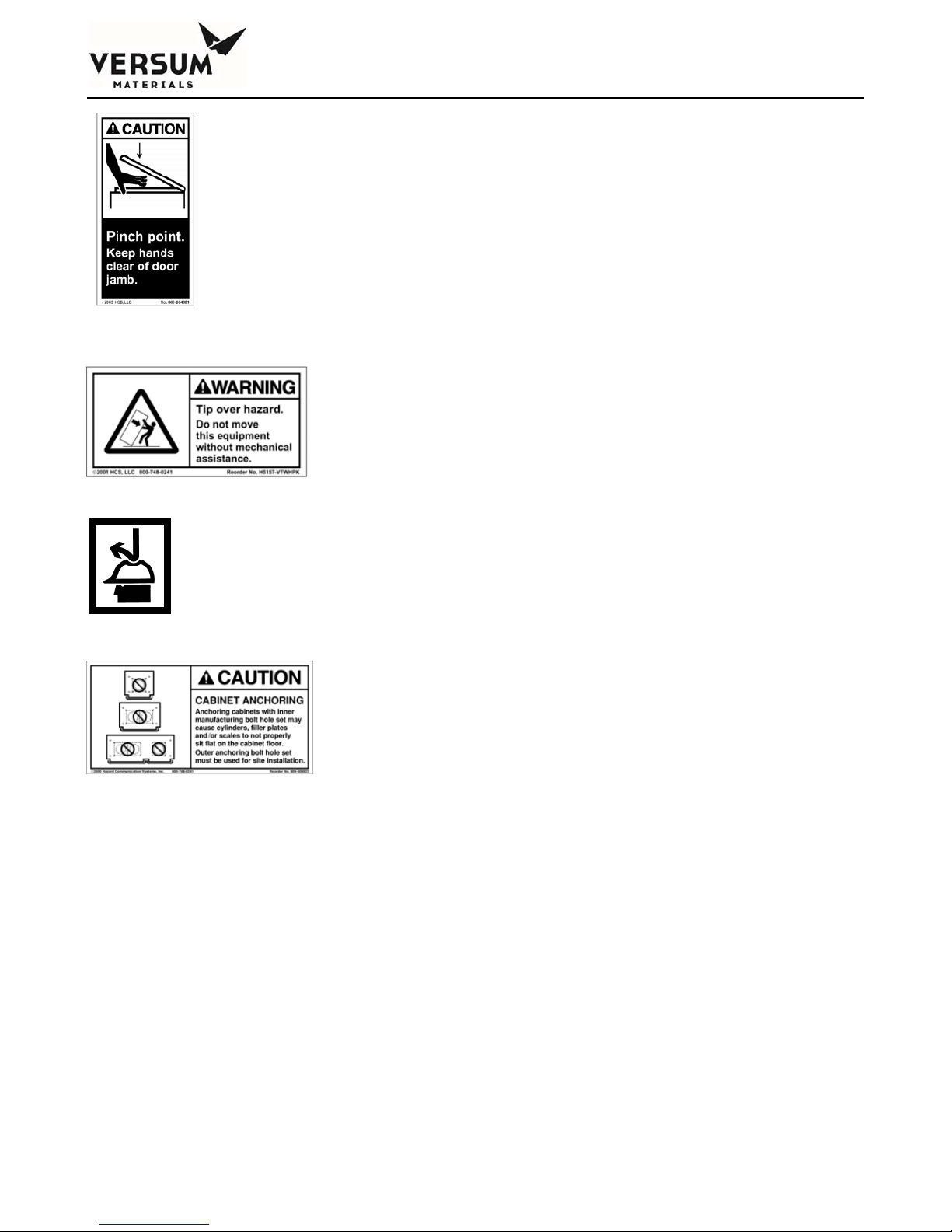
This symbol warns of a pinch hazard. This hazard exists
on cabinet doors equipped with automatic closers.
This symbol warns of the possibility of the
source system tipping over if it is not installed
properly. Personal injury could result.
This symbol indicates the need for head protection.
This symbol cautions against the improper
anchoring of cabinets.
_______________________________________________________________________________________________________________
MNL000127 Revision 8 07/27/2016
Gas Equipment
© Versum Materials, Inc. as of the revision and date shown. All rights reserved.
Page 1 - 4
Confidential and Proprietary Data
Page 13
Chapter 1 - Safety Warnings
1.2 Important Safety Warnings
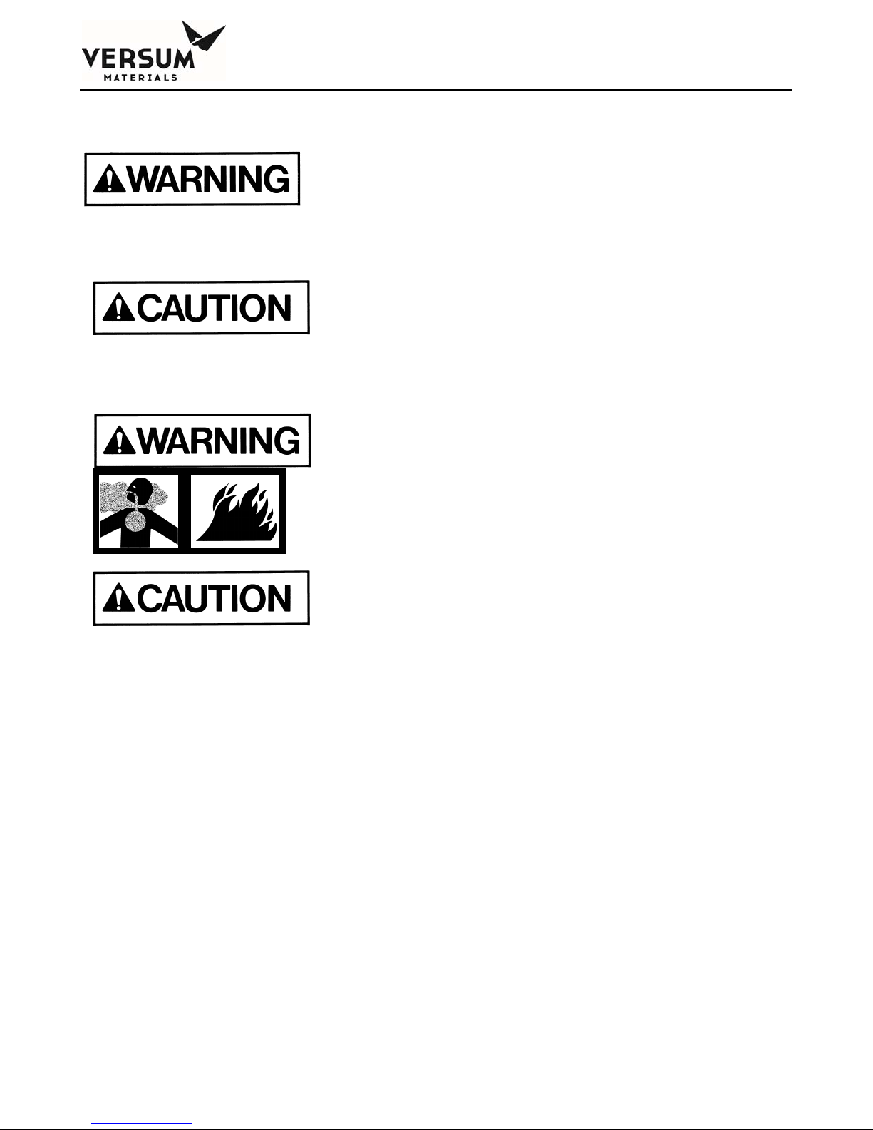
Failure to read, understand and follow the
safety information found in this section
could result in personal injury and death.
The operator must read and understand
this safety section before operating the
system. All operating and maintenance
personnel must receive training and
instruction by Versum Materials, Inc.
All cylinder storage areas must be
continually monitored with an air quality
monitor to prevent the danger of a
hazardous atmosphere.
Before using the system, review your
company's requirements for use of toxic,
corrosive, flammable, pyrophoric, oxidizers
and inert gas cylinders and electrically
powered equipment. You must be
thoroughly trained in your company's
safety procedures and safety equipment
(self-contained breathing apparatus,
emergency shutdown systems, plant alarm
locations, etc.)
_______________________________________________________________________________________________________________
MNL000127 Revision 8 07/27/2016
Gas Equipment
© Versum Materials, Inc. as of the revision and date shown. All rights reserved.
Page 1 - 5
Confidential and Proprietary Data
Page 14
Chapter 1 - Safety Warnings
1.3 Inert Gas Hazards
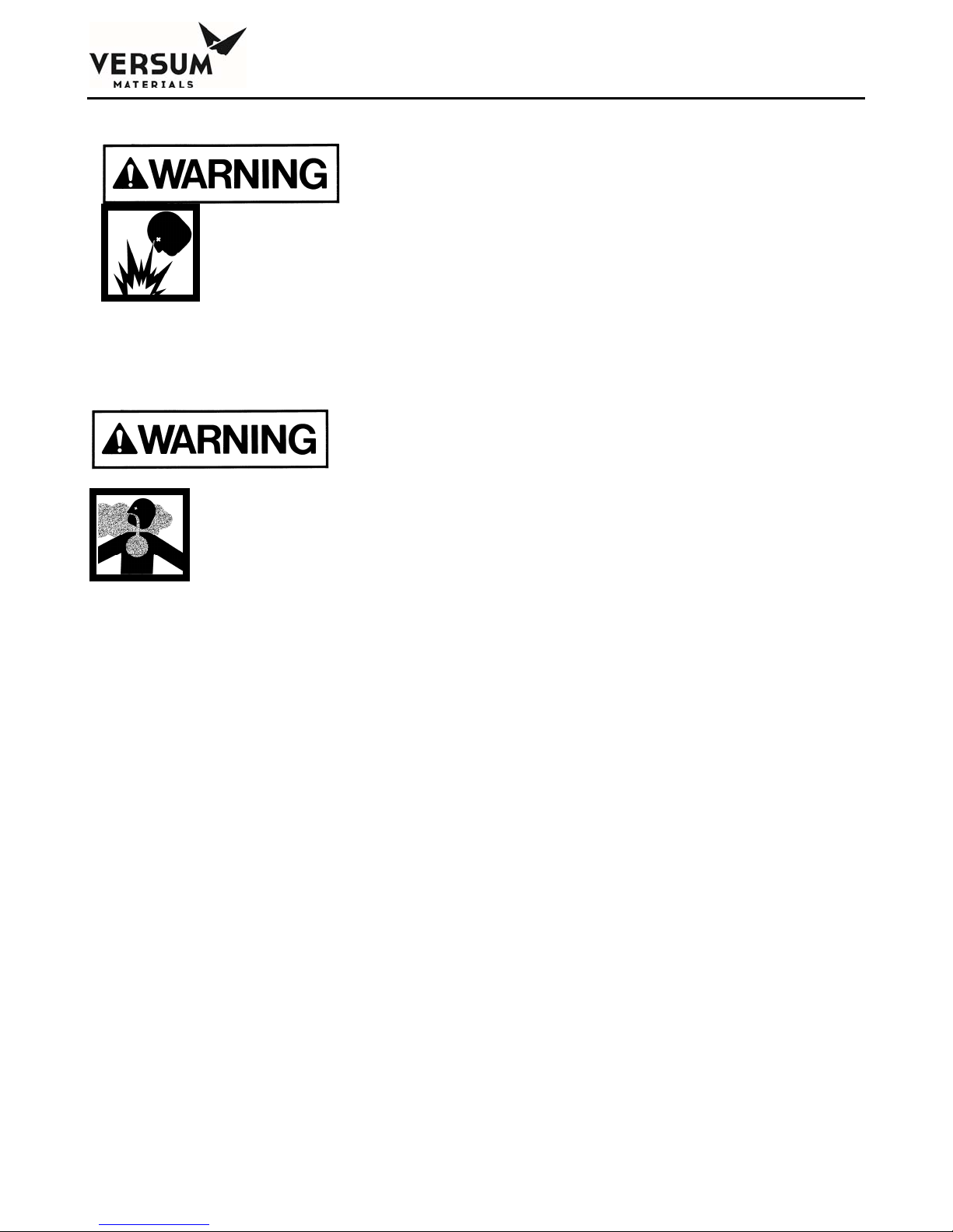
Do not use this device in any manner other
than specified in this manual.
Do not make any changes to the equipment
independently. INJURY or DEATH may
result from unauthorized modifications.
All modifications to equipment MUST be
approved in writing by an Versum
Materials, Inc.' Representative.
High concentrations of nitrogen, helium, or
other inert gases can cause an oxygen
deficient atmosphere in a confined area
which can cause DEATH. All personnel
must read and understand the material
safety data sheet(s) (MSDS) for the specific
gas(es) being used.
Oxygen concentrations of 19.5% or less can greatly increase the hazard of asphyxiation to personnel.
Before working in an area where nitrogen, helium or other inert gases could be present, check the area
with an oxygen monitor to be sure the oxygen concentration is between 19.5% and 23%. While
working in the area, the oxygen concentration needs to be monitored with a continuous oxygen
monitor. Always provide adequate ventilation in the work area to decrease the risk of an oxygen
deficient atmosphere.
Personnel in an oxygen deficient atmosphere will not realize they are being asphyxiated. Breathing of
pure inert gases will cause immediate unconsciousness. Symptoms of asphyxia include:
Rapid breathing
Nausea
Vomiting
Inability to move
Convulsive movements
Collapse
Abnormal pulse
Rapid fatigue
_______________________________________________________________________________________________________________
MNL000127 Revision 8 07/27/2016
Gas Equipment
© Versum Materials, Inc. as of the revision and date shown. All rights reserved.
Page 1 - 6
Confidential and Proprietary Data
Page 15

Chapter 1 - Safety Warnings
Faulty judgment
Insensitivity to pain
Abnormal emotions
Remove any personnel in an oxygen deficient atmosphere to fresh air. Get medical attention
immediately. Positive pressure breathing apparatus must be worn by any rescuers entering a
suspected oxygen deficient atmosphere.
Nitrogen gas may accumulate in low or confined areas. All requirements of OSHA 1910.146
(Confined Space Guidelines) must be met when inert gases may be present in confined spaces. Self
contained breathing apparatus is required (cartridge or filter type gas masks cannot be used). See the
information on personal protective equipment in this section for details.
When entering a confined area or area which may contain high inert gas concentrations, a "Buddy
System" must be used. One person should remain outside the suspect area, but within view of the
other person. This method ensures that the other person can respond in the event of an emergency.
1.4 Pressurized Fluids / Gases
Pressurized gas and water sprinkler lines
can injure personnel and damage
equipment. Never tighten or loosen a fitting
when it is under pressure.
The house nitrogen supply lines can contain pressures of 100+ psig (6.9+ barg). The water sprinkler
lines contain pressures of 30 psig (2.1 barg). Exercise care when working around these lines. Ensure
that pressure has been vented before breaking any connection. Tag out and lock out the line before
doing any work. Follow Typical Minimal Lockout or Tagout System Procedures described by
Occupational Safety and Health Admin., Labor Para. 1910.147.
1.5 Electrical Hazard
Electric shock can cause personal injury or death.
_______________________________________________________________________________________________________________
MNL000127 Revision 8 07/27/2016
Gas Equipment
© Versum Materials, Inc. as of the revision and date shown. All rights reserved.
Page 1 - 7
Confidential and Proprietary Data
Page 16

Chapter 1 - Safety Warnings
The control circuits for the system use 115/220 VAC, 50/60 Hz. Do not attempt to work on the system
without first turning the power off and tagging out and locking out the electrical supply disconnect
switch per plant lock out procedures. Follow the Typical Minimal Lockout or Tagout System
Procedures described by Occupational Safety and Health Admin., Labor Para. 1910.147.
1.6 Falling Equipment Hazard
This system is a top heavy device. If it is not
properly installed, it could fall and injure,
crush or kill personnel working in the area.
When moving and installing the system, extreme care needs to be taken to support it properly. Due to
the top heavy nature of the system, when moving or if not installed properly, it could tip over, injuring,
crushing or possibly killing personnel in the area. Moving and setting equipment shall be done only by
those persons having proper training and qualification in lifting and rigging.
1.7 Gas Cylinder Handling Hazard
Improper handling and storage of
compressed and liquefied gas cylinders could
cause injury or death.
Restrain gas cylinders during storage and use. Keep protective cap on cylinder when not dispensing
gas. Lifting gas cylinders could cause strain or injury. See Safetygrams found in the Safety section of
the Operation Manual.
_______________________________________________________________________________________________________________
MNL000127 Revision 8 07/27/2016
Gas Equipment
© Versum Materials, Inc. as of the revision and date shown. All rights reserved.
Page 1 - 8
Confidential and Proprietary Data
Page 17

Chapter 1 - Safety Warnings
1.8 Pinch Hazard
A pinch hazard exists on cabinet doors
equipped with automatic closers.
1.9 Personal Protective Equipment
Personal protective equipment, as defined in
this section, must be worn when working
with this system.
Personal protective equipment is designed to protect personnel from inadvertent risk. The listed
personal protective equipment must be worn regardless of operator or technician level of training and
qualifications.
The minimum personal protective equipment required for operating and maintaining the
GASGUARD® system is dependent on the hazard category of the gas(es) being used. When a gas
meets more than one hazard category, the PPE for the most hazardous category must be used. Refer to
the hazard warnings in Section 1.10 for the hazards of the gas(es) being used.
In addition to the personal protective equipment, the following safety equipment is highly
recommended and is required when VERSUM MATERIALS, INC. personnel operate this equipment.
This equipment should be supplied by the customer prior to operating the GASGUARD® system.
Safety shower
Emergency phones
Eye wash
Gas leak detection system for gases to be used (ex: MDA)
The gas leak detection system must warn personnel (through visible and audible alarms located
near the gas cabinet) of a hazardous atmosphere. The gas sensor(s) need to be set up to alarm
_______________________________________________________________________________________________________________
MNL000127 Revision 8 07/27/2016
Gas Equipment
© Versum Materials, Inc. as of the revision and date shown. All rights reserved.
Page 1 - 9
Confidential and Proprietary Data
Page 18

Chapter 1 - Safety Warnings
at the lowest level of hazard of exposure. Upon activation of an alarm, follow the established
shutdown procedures for your system.
Scrubber with a pollution abatement system sized for maximum potential upset flow of
hazardous gas.
Adequate ventilation as described in section 3.7.
If you are unsure what personal protective
equipment list to follow for the gases being
used, DO NOT continue. Failure to
understand the hazards and use the proper
personal protective equipment may cause
INJURY or DEATH. Contact Versum
Materials, Inc. for the gas category.
Personal Protective Equipment for the gas categories follows:
Personal Protective Equipment for Toxics
Toxic gas leak detection (ex. MDA)
Self contained positive pressure breathing apparatus
Long sleeved Nomex suit
Safety glasses with side shields
Leather gloves
Safety shoes
NOTE: Most highly toxics (diborane, germane phosphine) are also
flammable. Nomex suit is not required for non-flammable toxics (ex:
nitrogen dioxide, boron trifluoride). All gases in Chapter 1 Section 12
using the warning sign with POISON GAS on the left and
FLAMMABLE GAS on the right REQUIRE the Nomex suit.
Personal Protective Equipment for Corrosives
Corrosive gas leak detector (ex. MDA)
Self contained positive pressure breathing apparatus
Level C acid suit (jacket with bib overalls)
_______________________________________________________________________________________________________________
MNL000127 Revision 8 07/27/2016
Gas Equipment
© Versum Materials, Inc. as of the revision and date shown. All rights reserved.
Page 1 - 10
Confidential and Proprietary Data
Page 19

Chapter 1 - Safety Warnings
Safety glasses with side shields
Leather gloves
Safety shoes
NOTE: Either air quality monitoring or self contained breathing
apparatus is required for corrosive gases. Versum Materials, Inc.
recommends the use of both. It is not required to use both, however at
least one MUST be used at all times.
Personal Protective Equipment for Pyrophorics
Pyrophoric gas leak detection (ex: MDA)
Hard hat (fire hat with brim recommended)
Long sleeved Nomex suit
Face shield
Safety glasses with side shields
Leather gloves
Safety shoes
Personal Protective Equipment for Flammables
Hard hat (fire hat with brim recommended)
Long sleeved Nomex suit
Face shield
Safety glasses with side shields
Leather gloves
Safety shoes
Personal Protective Equipment for Inerts
Oxygen depletion monitor
Safety glasses with side shields
Leather gloves
Safety shoes
_______________________________________________________________________________________________________________
MNL000127 Revision 8 07/27/2016
Gas Equipment
© Versum Materials, Inc. as of the revision and date shown. All rights reserved.
Page 1 - 11
Confidential and Proprietary Data
Page 20

Chapter 1 - Safety Warnings
1.10 Hazard Warnings
The following hazard warnings detail system hazards. Follow the warnings to avoid personal injury or
death. Do not work on the system before reading and understanding the following warnings. The
hazard warnings include:
Toxic Gases Hazards
Corrosive Gases Hazards
Flammable and Pyrophoric Gases Hazards
Oxidizer Hazards
Inert Gas Hazards
Pressurized Gases
Cylinder Handling Hazards
Electrical Hazards
Not all of the gas related hazards may apply to your system. For example, you may not be using any
gases in the oxidizer class.
Some gases have more than one hazard. For
example, fluorine is toxic, corrosive and also an
oxidizer.
The Pressurized Gases Cylinder Handling Hazards and Electrical Hazard warnings apply to all
GASGUARD® systems.
The following is general information on
typical gas hazards. It is not a substitute for
training and use of Material Safety Data
Sheets by all operators.
_______________________________________________________________________________________________________________
MNL000127 Revision 8 07/27/2016
Gas Equipment
© Versum Materials, Inc. as of the revision and date shown. All rights reserved.
Page 1 - 12
Confidential and Proprietary Data
Page 21

Chapter 1 - Safety Warnings
1.10.1 Toxic Gas Hazards
Many of the gases used in the GASGUARD®
system could cause personal INJURY OR
DEATH at very low concentrations.
Many of these gases provide no physical warning signs (i.e. coughing, throat irritation, burning
sensations, and shortness of breath) to alert personnel of exposure to toxic levels.
Personal protective equipment required for use with toxic gases is detailed in Chapter 1 Section 9 of
this manual.
A list of most of the toxic gases used in the GASGUARD® system follows:
Ammonia Hydrogen fluoride
Arsine Hydrogen sulfide
Boron trichloride Methyl chloride
Boron trifluoride Nitrogen dioxide
Carbon monoxide Nitrogen trifluoride
Chlorine Phosphine
Chlorine trifluoride Phosphine mixtures
Diborane Phosphorous pentafluoride
Diborane mixtures Silane
Dichlorosilane Silicon tetrachloride
Disilane Silicon tetrafluoride
Fluorine Sulfur tetrafluoride
Germane Trichlorosilane
Hydrogen bromide Tungsten hexafluoride
Hydrogen chloride
_______________________________________________________________________________________________________________
MNL000127 Revision 8 07/27/2016
Gas Equipment
© Versum Materials, Inc. as of the revision and date shown. All rights reserved.
Page 1 - 13
Confidential and Proprietary Data
Page 22

Chapter 1 - Safety Warnings
1.10.2 Corrosive Gas Hazards
Corrosives such as chlorine, fluorine and
ammonia will irritate and burn human tissue.
They can cause personal INJURY and DEATH.
Exposure to very small concentrations of corrosive gases can cause severe irritation of the eyes and
respiratory system. At higher concentrations, they can cause severe personal injury or death.
Chapter 1 Section 9 of this manual lists the personal protective equipment required for use with
corrosive gases.
A list of most of the corrosive gases used in the GASGUARD® system follows:
Ammonia Hydrogen chloride
Boron trichloride Hydrogen fluoride
Boron trifluoride Hydrogen sulfide
Chlorine Nitrogen dioxide
Chlorine trifluoride Phosphorous pentafluoride
Dichlorosilane Silicon tetrachloride
Fluorine Silicon tetrafluoride
Hydrogen bromide Tungsten hexafluoride
1.10.3 Flammable and Pyrophoric Gas Hazards
Flammable and pyrophoric gases could cause
fire, explosions, personal injury or death.
_______________________________________________________________________________________________________________
MNL000127 Revision 8 07/27/2016
Gas Equipment
© Versum Materials, Inc. as of the revision and date shown. All rights reserved.
Page 1 - 14
Confidential and Proprietary Data
Page 23

Chapter 1 - Safety Warnings
Pyrophoric gases will spontaneously ignite in air
Pyrophoric gases do not need a source of ignition to burn. However, low concentrations may
accumulate without pyrophoric ignition (i.e. silane can accumulate up to a concentration of 2 molar
percent [number of moles of silane per fixed volume of air] before spontaneous ignition occurs).
Pyrophoric gases will ignite in the presence of oxygen.
Flammable mixtures can burn or explode
Fire and explosion hazards can be controlled by preventing the formation of combustible fuel-oxidant
mixtures and by eliminating sources of ignition such as sparks, open flames or other heat sources.
Flammable mixtures will burn when ignited and can explode when the concentration is above the
lower explosive limit (LEL) and below the upper explosive limit (UEL) for that specific gas. Some
flammable gases may accumulate as pockets in enclosed areas and subsequently explode if an ignition
source is present. A flammable gas also presents an asphyxiating hazard in sufficient quantities to
reduce oxygen concentration below 19.5%, however fire/explosion is typically the primary hazard.
Adequate ventilation is necessary
Adequate ventilation helps reduce the possible formation of flammable mixtures in the event of a
flammable gas leak. See tables in Chapter 3 Section 7 which list the exhaust requirements per
enclosure size for all gases.
NOTE: To avoid any possible hazardous reactions (i.e. fire, explosion,
extremely corrosive or toxic mixtures) never vent incompatible gases out the
same duct!
Continually monitor the atmosphere
Continually monitoring the atmosphere with a gas leak detector will alert the operator to a flammable
or explosive atmosphere in the area.
NOTE: The installation of a hydride detector is strongly recommended for
silane and other pyrophoric gases to detect leaks or pockets of gas that may not
spontaneously ignite!
Versum Materials, Inc. strongly recommend installation of a hydride detector to detect gas pocketing
of pyrophoric gases.
_______________________________________________________________________________________________________________
MNL000127 Revision 8 07/27/2016
Gas Equipment
© Versum Materials, Inc. as of the revision and date shown. All rights reserved.
Page 1 - 15
Confidential and Proprietary Data
Page 24

Chapter 1 - Safety Warnings
Guidelines to avoid forming combustible mixtures
Avoid forming combustible mixtures by adhering to the following:
Do not admit flammable gases into an area that contains oxygen/air. Do not admit
oxygen/air into an area that contains flammable gases.
Maintain a small positive pressure in systems to prevent air from leaking into them when
the equipment is shut down.
Avoid venting of flammable gases through vents that do not contain an inert atmosphere.
Personal protective equipment required for use with pyrophoric and flammable gases is listed in
Chapter 1 Section 9. Note that the personal protective equipment (PPE) for pyrophorics differs from
the flammables. Be sure to use the proper PPE.
A list of most of the pyrophoric gases used in the GASGUARD® system follows:
Diborane Phosphine
Disilane Silane
A list of most of the flammable gases used in the GASGUARD® system follows:
Acetylene Germane
Ammonia Hydrogen
Arsine Hydrogen mixtures
Carbon monoxide Hydrogen sulfide
Diborane Methane
Diborane mixtures Methyl chloride
Dichlorosilane Methyl fluoride
Disilane Trichlorosilane
1.10.4 Oxygen and Other Oxidizer Hazards
Systems using oxygen or other oxidizers
(i.e. nitrous oxide, fluorine) have specific
guidelines for specifying equipment, materials
of construction and system cleanliness. Failure
to comply with materials of construction and
system cleanliness could result in injury or
death.
_______________________________________________________________________________________________________________
MNL000127 Revision 8 07/27/2016
Gas Equipment
© Versum Materials, Inc. as of the revision and date shown. All rights reserved.
Page 1 - 16
Confidential and Proprietary Data
Page 25

Chapter 1 - Safety Warnings
Follow safe practices when using oxygen or oxidizers (chlorine and fluorine)
Oxygen concentrations in excess of 23% significantly increase the hazard exposure to personnel and
equipment. Those materials which burn in air will burn more violently and explosively in
oxygen/oxidizer enriched atmospheres. Guidelines for oxygen systems are found in CGA Pamphlet G-
4.4. (Contact your gas supplier or the Compressed Gas Association to order CGA Pamphlets.) Only
those personnel who have read and understand the hazards of oxygen or oxidizers and safe practices
for these systems should be permitted to operate and maintain the system.
Use only equipment specifically designed for oxygen or oxidizer service.
Inappropriate materials of construction increase the danger of ignition of pipelines and controls. Pipe
sizing is just as important to ensure all velocity restrictions for oxygen or oxidizers are met. Do not
substitute components or equipment without considering these hazards. Refer to CGA Pamphlet G-4.4
for guidelines and specifications of oxygen systems. (Contact your gas supplier or the Compressed
Gas Association to order CGA Pamphlets.)
Maintain oxygen cleanliness at all times.
All equipment and piping in contact with oxygen or oxidizers must be cleaned to specifications
outlined in CGA Pamphlet G-4.1. (Contact your gas supplier or the Compressed Gas Association to
order CGA Pamphlets.) Failure to clean components and piping increases the danger of ignition and
fire. Note that the cleaning solvent must be thoroughly removed before the equipment can be placed
into service. Maintain cleanliness during assembly, installation, and repair.
No open flames, smoking, or sparks permitted near oxygen equipment.
Since many materials will burn in oxygen/oxidizer enriched atmospheres, the best method in
preventing fires is to eliminate sources of ignition. Where this control equipment is being used or
where concentrations of oxygen are greater than 23%, avoid open flames, sparks, or sources of heat.
Never weld on a pressurized line flowing oxygen or an oxidizer. Make sure signs are posted warning
personnel that oxygen or oxidizers are in use.
Do not substitute oxygen for compressed air.
Substituting oxygen for compressed air is dangerous. Explosions can occur when oxygen is
substituted for air. Chances are the instrument air equipment is not compatible or cleaned for oxygen
service. Oxygen used to clean off equipment or clothing could come in contact with a source of
ignition (spark, flame, or other) and ignite. In some cases, the elevated oxygen levels could linger
even after the source has been shut off. Never tie into an oxygen system for personal breathing
purposes.
_______________________________________________________________________________________________________________
MNL000127 Revision 8 07/27/2016
Gas Equipment
© Versum Materials, Inc. as of the revision and date shown. All rights reserved.
Page 1 - 17
Confidential and Proprietary Data
Page 26

Chapter 1 - Safety Warnings
A list of most of the oxidizers used in the GASGUARD® system follows:
Chlorine Nitrogen trifluoride
Chlorine trifluoride Nitrous oxide
Fluorine Oxygen
1.10.5 Inert Gas Hazards
High concentrations of nitrogen, helium, or
other inert gases will cause an oxygen deficient
atmosphere in a confined area which can cause
DEATH. All personnel must read and
understand the Material Safety Data Sheet(s)
Oxygen concentrations of 19.5% or less can greatly increase the hazard of asphyxiation to personnel.
Before working in an area where nitrogen, helium or other inert gases could be present, check the area
with an oxygen monitor to be sure the oxygen concentration is between 19.5% and 23%. While
working in the area, the oxygen concentration needs to be monitored with a continuous oxygen
monitor. Always provide adequate ventilation in the work area to decrease the risk of an oxygen
deficient atmosphere. Read VERSUM MATERIALS, INC. Safetygram 17 "Dangers of Oxygen
Deficient Atmospheres" included in the safety literature in Section 1.14 of this manual.
(MSDS) for the specific gas(es) being used.
Any time an oxygen deficient atmosphere is suspected, the proper personal protective equipment must
be used. See the information on personal protective equipment in Chapter 1 Section 9 for details.
Personnel in an oxygen deficient atmosphere will not realize they are being asphyxiated. Breathing of
pure inert gases will cause immediate unconsciousness.
Symptoms of asphyxia include:
Rapid breathing
Nausea
Vomiting
Inability to move
Convulsive movements
Collapse
Abnormal pulse
_______________________________________________________________________________________________________________
MNL000127 Revision 8 07/27/2016
Gas Equipment
© Versum Materials, Inc. as of the revision and date shown. All rights reserved.
Page 1 - 18
Confidential and Proprietary Data
Page 27

Chapter 1 - Safety Warnings
Rapid fatigue
Faulty judgment
Insensitivity to pain
Abnormal emotions
Remove any personnel in an oxygen deficient atmosphere to fresh air. Get medical attention
immediately. Use cardiopulmonary resuscitation if the victim is not breathing. Positive pressure
breathing apparatus must be worn by any rescuers entering a suspected oxygen deficient
atmosphere.
Nitrogen gas may accumulate in low or confined areas. All requirements of OSHA 1910.146
(Confined Space Guidelines. ) must be met when working with inert gases in confined spaces. Self
contained breathing apparatus is required (cartridge or filter type gas masks cannot be used). See the
information on personal protective equipment in this section for details.
When entering a confined area or area which may contain high inert gas concentrations, a "Buddy
System" must be used. One person should remain outside the suspect area, but within view of the
other person. This method ensures that the other person can respond in the event of an emergency.
Personal protective equipment required for use with inerts is listed in Chapter 1 Section 9.
A list of inert gases used in the GASGUARD® system follows:
Argon Halocarbon 115
Carbon Dioxide Halocarbon 116
Halocarbon 11 Helium
Halocarbon 12 Krypton
Halocarbon 13 Neon
Halocarbon 14 Nitrogen
Halocarbon 22 Perfluoropropane
Halocarbon 23 Sulfur Hexafluoride
Halocarbon 113 Xenon
_______________________________________________________________________________________________________________
MNL000127 Revision 8 07/27/2016
Gas Equipment
© Versum Materials, Inc. as of the revision and date shown. All rights reserved.
Page 1 - 19
Confidential and Proprietary Data
Page 28
Chapter 1 - Safety Warnings
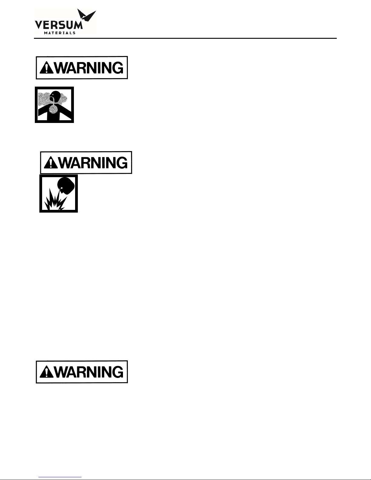
1.10.6 Pressurized Gases
Any gas, in addition to those listed above,
used in the GASGUARD® system could
potentially displace the oxygen in the air
and cause asphyxiation.
Pressurized gas lines could injure personnel
and damage equipment. Never tighten or
loosen a fitting when it is under pressure.
The process and purge gas cylinders can contain pressures up to 2650 psig in the USA. In Europe,
cylinders can contain pressures up to 200 barg. A leak from a loose mechanical fitting, component or a
ruptured/failed component can expose the operator to a high pressure gas stream or projectile. Read
the cylinder handling warnings in Chapter 1 Section 1.10.7 and the safety literature on cylinder
handling in Chapter 1 Section 13.
The house nitrogen supply lines can contain pressures of 100+ psig (7+ barg). Exercise care when
working around these lines. Insure that pressure has been vented before breaking any connection. Tag
out and lock out the line before doing any work. Follow Typical Minimal Lockout or Tagout System
Procedures described by Occupational Safety and Health Admin., Labor Para. 1910.147 found in
Section 1.11.
1.10.7 Cylinder Handling Hazards
High pressure gas cylinders could be
extremely hazardous when not handled
properly.
Proper training, maintenance, leak testing and mechanical connection procedures can prevent operators
from being exposed to high pressure gas streams. Use the cylinder change out procedures in Chapter
8 Section 8.3.2, "Process Cylinder Procedures."
_______________________________________________________________________________________________________________
MNL000127 Revision 8 07/27/2016
Gas Equipment
© Versum Materials, Inc. as of the revision and date shown. All rights reserved.
Page 1 - 20
Confidential and Proprietary Data
Page 29

Chapter 1 - Safety Warnings
Do not use a wrench or other device to close diaphragm type cylinder valves. This could
cause diaphragm rupture and valve failure which could result in personal injury or death.
Contact your gas supplier for the maximum torque (ft./lbs. or N/m) allowed on diaphragm
type cylinder valves. Certain gases are supplied with cylinder valves without handwheels.
Use only the tool specified by your gas supplier to open and close diaphragm type cylinder
valves to avoid over torquing these valves.
If a cylinder valve protection cap is extremely difficult to remove, do not apply excessive
force or pry the cap loose. Attach a label to the cylinder identifying the problem and notify
the personnel responsible for returning cylinders about the defective cylinder. Obtain
another cylinder. Do not attempt to open a frozen cap as this would damage the cylinder
valve and could result in personal injury or death.
Do not rotate the cylinder using the cylinder valve handle. This may open the cylinder valve
and cause a high pressure gas leak.
NEVER replace the gas specified for use in the source system with another type of gas
cylinder. Incompatible gases could cause fires, explosions or extremely corrosive or toxic
mixtures which can cause personal injury or death. If another type of gas is required for
use in the gas source system, contact Versum Materials, Inc. immediately.
A valve outlet sealing cap must be supplied on all toxic, corrosive and pyrophoric gases.
Consult your gas supplier if there is no sealing cap on any of the above types of gas
cylinders.
Cylinder valves are available with removable flow restrictor orifices in the valve outlet for
use with gas cylinders. This flow restrictor orifice significantly limits the rate of release of
gas from the valve outlet during transportation, storage and use, due to a valve or system
failure. Verify that your gases are supplied in cylinders with valves that have the
appropriate flow restrictor orifice. Note that there are different size flow restrictor orifices
available. Verify that the correct size is being used for your specific situation. A quality
control program should be established to assure that your supplier has installed the correct
flow restrictor orifice in the valve outlet after the filling operation has been completed.
_______________________________________________________________________________________________________________
MNL000127 Revision 8 07/27/2016
Gas Equipment
© Versum Materials, Inc. as of the revision and date shown. All rights reserved.
Page 1 - 21
Confidential and Proprietary Data
Page 30

Chapter 1 - Safety Warnings
1.10.8 Electrical Hazards
Electric shock could cause personal injury
or death.
The control circuits for the system use 115/220 VAC, 50/60 Hz. Do not attempt to work on the system
without first turning the power off and tagging out and locking out the electrical supply disconnect
switch per plant lock out procedures. Follow the Typical Minimal Lockout or Tagout System
Procedures described by Occupational Safety and Health Admin., Labor Para. 1910.147 found in
Chapter 1 Section 11 of this manual.
1.10.9 Purge Gas Backstream Hazard
Avoid low pressure condition in purge gas
cylinder to prevent a backstream hazard.
The purge gas system incorporates a pressure indicating gage which will provide the means of
displaying a low purge gas cylinder pressure condition (usually 200 psig [14 barg] minimum). The
cylinder should be changed out at this point to prevent process gas from backstreaming into the purge
gas cylinder.
1.11 Typical Minimal Lockout or Tagout System Procedures
NOTE: The following OSHA document is included to help you develop a lockout/tagout procedure
for the GASGUARD® System. A written procedure is required for any work performed under
lockout/tagout. It must be reviewed, approved and understood by all participants who are trained to
perform the work. (Occupational Safety and Health Admin., Labor Para. 1910.147)
Although OSHA does not have jurisdiction outside the United States of America, it is Versum
Materials, Inc. recommendation that Lockout, or Tagout procedures be followed, except where local
laws are more stringent.
General
Lockout is the preferred method of isolating machines or equipment from energy sources. To assist
employers in developing a procedure which meets the requirements of the standard, the following
_______________________________________________________________________________________________________________
MNL000127 Revision 8 07/27/2016
Gas Equipment
© Versum Materials, Inc. as of the revision and date shown. All rights reserved.
Page 1 - 22
Confidential and Proprietary Data
Page 31

Chapter 1 - Safety Warnings
simple procedure is provided for use in both lockout and tagout programs. This procedure may be used
when there are a limited number of types of machines or equipment or there is a single power source.
For a more complex system, a more comprehensive procedure will need to be developed, documented
and utilized.
Lockout (or Tagout) Procedure for (Name of Company)
Purpose
This procedure establishes the minimum requirements for the lockout or tagout of energy isolating
devices. It shall be used to ensure that the machine or equipment is isolated from all potentially
dangerous energy, and locked out or tagged out before employees perform any servicing or
maintenance activities where the unexpected energization, start-up or release of stored energy could
cause injury (Type(s) and Magnitude(s) of Energy Hazards).
_______________________________________________________________________________________________________________
MNL000127 Revision 8 07/27/2016
Gas Equipment
© Versum Materials, Inc. as of the revision and date shown. All rights reserved.
Page 1 - 23
Confidential and Proprietary Data
Page 32

Chapter 1 - Safety Warnings
Responsibility
Appropriate employees shall be instructed in the safety significance of the lockout (or tagout)
procedure (Name(s)/Job title(s) of employees authorized to lockout or tagout). Each new or transferred
affected employee and other employees whose work operations are or may be in the area shall be
instructed in the purpose and use of the lockout or tagout procedure (Name(s)/Job title(s) of affected
employees and how to notify).
Preparation for Lockout or Tagout
Make a survey to locate and identify all isolating devices to be certain which switch(s), valve(s) or
other energy isolating devices apply to the equipment to be locked or tagged out. More than one energy
source (electrical, mechanical, or others) may be involved. (Type(s) of energy isolating means).
Sequence of Lockout or Tagout System Procedure
1. Notify all affected employees that a lockout or tagout system is going to be utilized and the reason
therefore. The authorized employee shall know the type and magnitude of energy that the machine
or equipment utilizes and shall understand the hazards thereof.
2. If the machine or equipment is operating, shut it down by the normal stopping procedure (depress
stop button, open toggle switch, etc.).
3. Operate the switch, valve, or other energy isolating device(s) so that the equipment is isolated from
its energy source(s). Stored energy (such as that in springs, elevated machine members, rotating
flywheels, hydraulic systems, and air, gas, steam or water pressure, etc.) must be dissipated or
restrained by methods such as repositioning, blocking, bleeding down, etc. (Type(s) of stored
energy methods to dissipate or restrain).
4. Lockout and/or tagout the energy isolating devices with assigned individual lock(s) or tag(s)
(Method(s) selected, i.e., locks, tags, additional safety measures, etc.)
5. After ensuring that no personnel are exposed, and as a check on having disconnected the energy
sources, operate the push button or other normal operating controls to make certain the equipment
will not operate (Type(s) of equipment checked to ensure disconnections).
Return operating control(s) to neutral or off
position after the test.
6. The equipment is now locked or tagged out.
_______________________________________________________________________________________________________________
MNL000127 Revision 8 07/27/2016
Gas Equipment
© Versum Materials, Inc. as of the revision and date shown. All rights reserved.
Page 1 - 24
Confidential and Proprietary Data
Page 33

Chapter 1 - Safety Warnings
Restoring Machines or Equipment to Normal Production Operations
1. After the servicing and/or maintenance are complete and equipment is ready for normal production
operations, check the area around the machines or equipment to ensure that no one is exposed.
2. After all tools have been removed from the machine or equipment, guards have been reinstalled
and employees are in the clear, remove all lockout or tagout devices. Operate the energy isolating
devices to restore energy to the machine or equipment.
Procedure Involving More Than One Person
In the preceding steps, if more than one individual is required to lockout or tagout equipment, each
shall place his/her own personal lockout device on the energy isolating devices(s). When an energy
isolating device cannot accept multiple locks or tags, a multiple lockout or tagout device (HASP) may
be used. If lockout is used, a single lock may be used to lockout the machine or equipment with the key
being placed in a lockout box or cabinet which allows the use of multiple locks to secure it. Each
employee will then use his/her own lock to secure the box or cabinet. As each person no longer needs
to maintain his/her lockout protection, that person will remove his/her lock from the box or cabinet
(Name(s)/Job title(s) of employees authorized for group lockout or tagout).
_______________________________________________________________________________________________________________
MNL000127 Revision 8 07/27/2016
Gas Equipment
© Versum Materials, Inc. as of the revision and date shown. All rights reserved.
Page 1 - 25
Confidential and Proprietary Data
Page 34

Chapter 1 - Safety Warnings
Basic Rules for Using Lockout or Tagout System Procedure
All equipment shall be locked or tagged out to protect against accidental or inadvertent operating when
such operation could cause injury to personnel. Do not attempt to operate any switch, valve or other
energy isolating device where it is locked or tagged.
Entry No. Description
1. Name of Company
2. Type(s) and Magnitude(s) of energy and hazards
3. Name(s)/Job title(s) of employees authorized to lockout or
tagout
4. Name(s)/Job title(s) of affected employees and how to
notify
5. Type(s) and Location of energy isolating means
6. Type(s) of stored energy
7. Method(s) selected, i.e. locks, tags, additional safety
measure, etc.
8. Type(s) of equipment checked to ensure disconnections
9. Name(s)/Job title(s) of employees authorized for group
lockout or tagout
1910.147 29 CFR Ch.XVII (7-1-90)
_______________________________________________________________________________________________________________
MNL000127 Revision 8 07/27/2016
Gas Equipment
© Versum Materials, Inc. as of the revision and date shown. All rights reserved.
Page 1 - 26
Confidential and Proprietary Data
Page 35
Chapter 1 - Safety Warnings
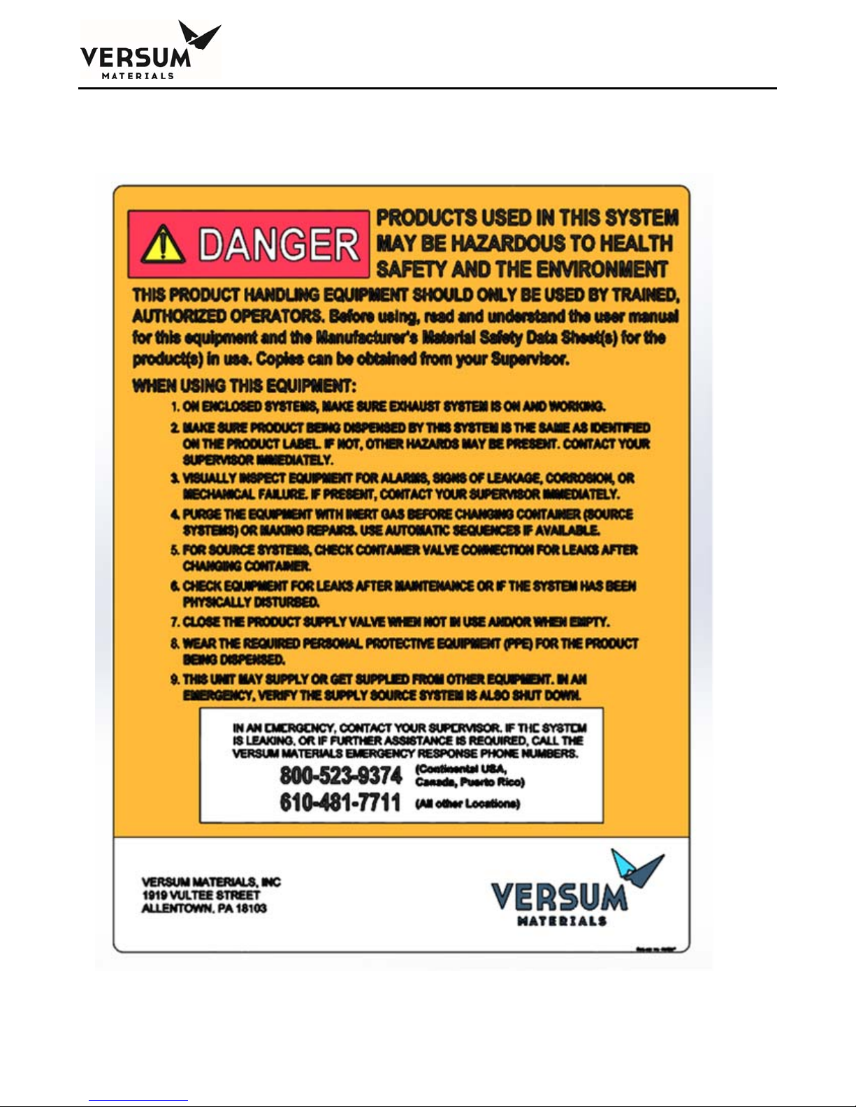
1.12 Safety Signs and Labels
The following sign is located on the exterior door of the GASGUARD® cabinet.
_______________________________________________________________________________________________________________
MNL000127 Revision 8 07/27/2016
Gas Equipment
© Versum Materials, Inc. as of the revision and date shown. All rights reserved.
Page 1 - 27
Confidential and Proprietary Data
Page 36
Chapter 1 - Safety Warnings
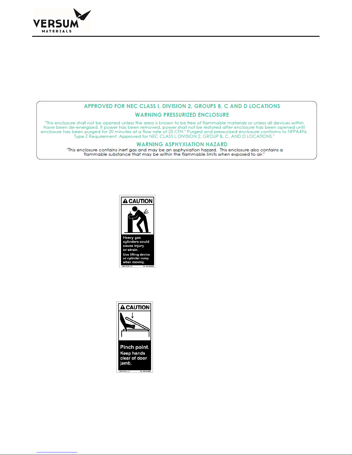
The following sign is located on the GASGUARD® controller. This label is required if the
GASGUARD® Source System is located in a Class I, Division II rated area (United States) or in a
Group 2, Category 3 ATEX rated area (Europe). Acetylene systems will have the same label as shown
below, but they will be approved for NEC Class I, Division 2, Groups A, B, C, and D Locations.
The following label appears inside cabinets containing cylinders. It is located on the inside door,
approximately at eye level. It is also located on the cylinder strap on both cabinets and racks.
The following label appears inside doors of cabinets.
_______________________________________________________________________________________________________________
MNL000127 Revision 8 07/27/2016
Gas Equipment
© Versum Materials, Inc. as of the revision and date shown. All rights reserved.
Page 1 - 28
Confidential and Proprietary Data
Page 37
Chapter 1 - Safety Warnings
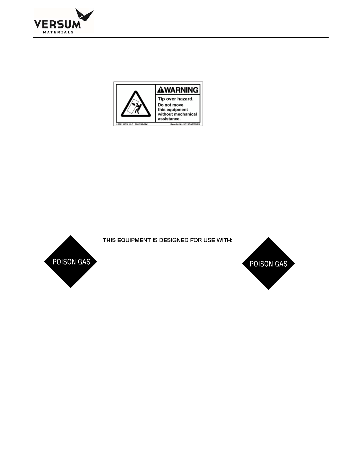
The following label appears on cabinets. It is located on the back of the cabinet, approximately 12”
(305 mm) from the top.
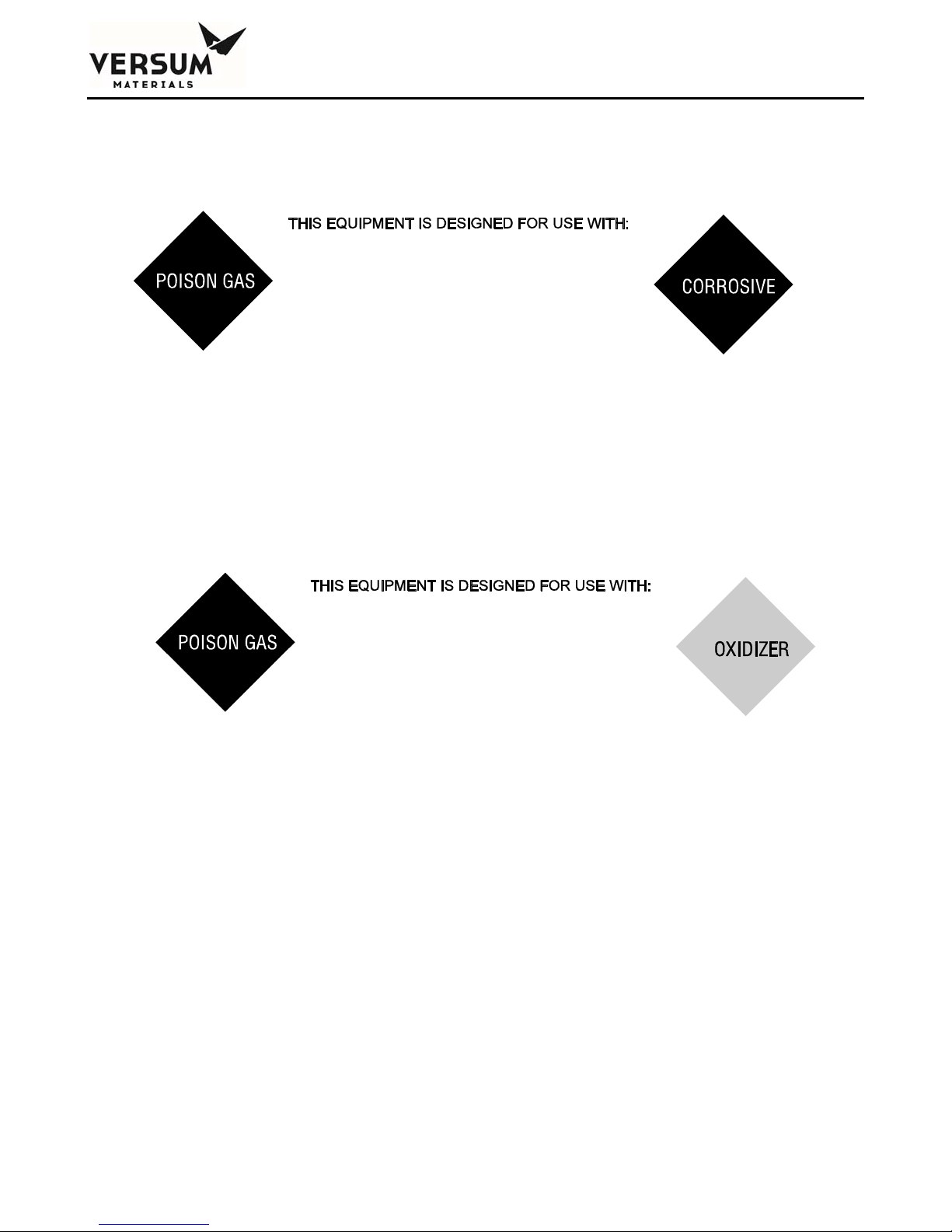
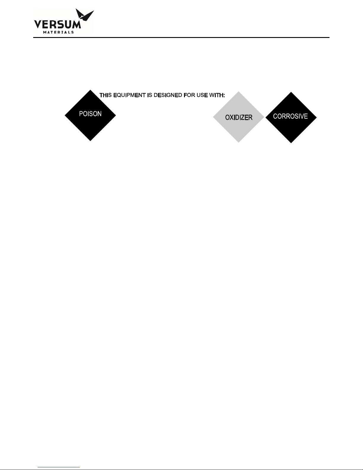
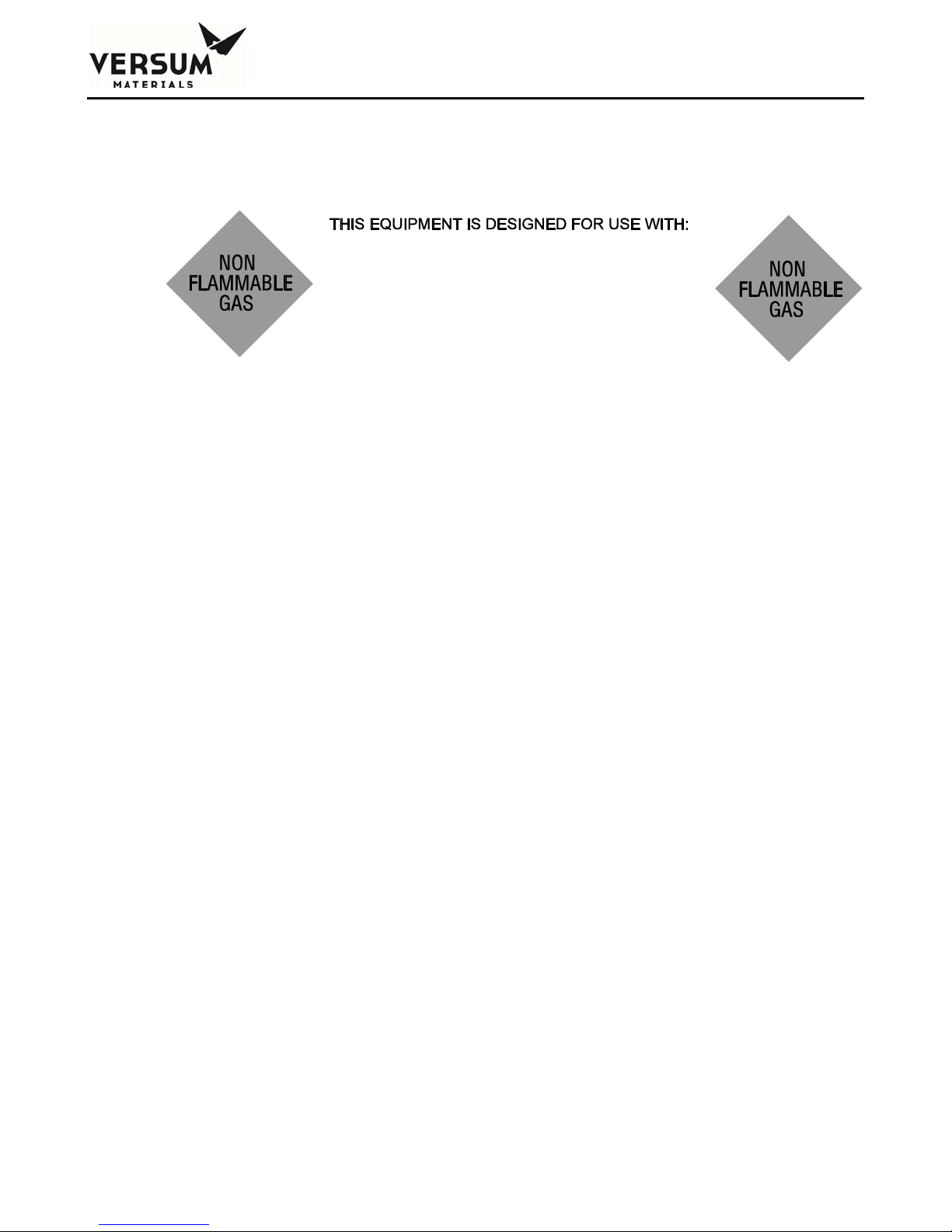
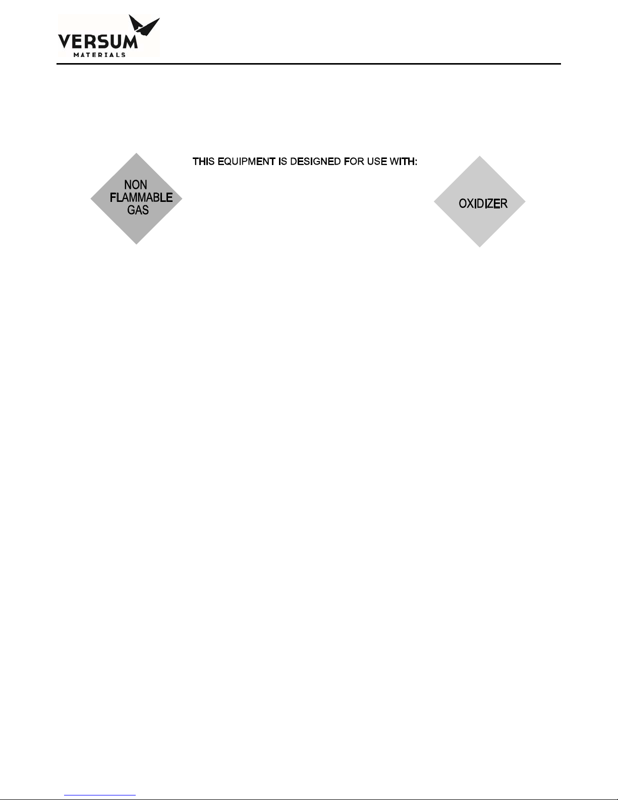
The following eleven labels are specific to the gases being used. They are located on the door of the
GASGUARD® cabinet. They are identical to the labels on the process gas cylinder in the
GASGUARD® cabinet to provide verification that the correct process gas is being installed and used.
NOTE: The signs shown below are United States DOT classifications. They are not
to be used to classify gas hazards. Refer to the appropriate MSDS provided with the
system documentation.
The following label would be used with the gases listed below it:
Boron trifluoride Phosphorous pentafluoride
Chlorine Sulfur dioxide
Carbon tetrachloride Sulfur tetrafluoride
Nitrogen dioxide Tungsten hexafluoride
Nitric oxide
_______________________________________________________________________________________________________________
MNL000127 Revision 8 07/27/2016
Gas Equipment
© Versum Materials, Inc. as of the revision and date shown. All rights reserved.
Page 1 - 29
Confidential and Proprietary Data
Page 38
Chapter 1 - Safety Warnings
The following label would be used with the gases listed below it:
Boron trichloride Hydrogen fluoride
Hydrogen bromide Silicon tetrafluoride
Hydrogen chloride
The following label would be used with the gases listed below it:
Fluorine Fluorine mixtures
_______________________________________________________________________________________________________________
MNL000127 Revision 8 07/27/2016
Gas Equipment
© Versum Materials, Inc. as of the revision and date shown. All rights reserved.
Page 1 - 30
Confidential and Proprietary Data
Page 39

Chapter 1 - Safety Warnings
The following label would be used with the gases listed below it:
Acetylene Hydrogen mixtures
Butane Isobutane
Disilane Isobutylene
Deuterium Methane
Ethane Methyl chloride
Ethanol mixtures Methyl silane
Ethylene Propane
Halocarbon 32 Silane
Halocarbon 41 Silane mixtures
Hydrogen
_______________________________________________________________________________________________________________
MNL000127 Revision 8 07/27/2016
Gas Equipment
© Versum Materials, Inc. as of the revision and date shown. All rights reserved.
Page 1 - 31
Confidential and Proprietary Data
Page 40

Chapter 1 - Safety Warnings
The following label would be used with the gases listed below it:
Arsine mixtures Germane
Carbon monoxide Hydrogen selenide
Diborane mixtures Hydrogen sulfide
Dichlorosilane Phosphine mixtures
Diethyl telluride
The following label would be used with the gases listed below it:
Silicon tetrachloride
_______________________________________________________________________________________________________________
MNL000127 Revision 8 07/27/2016
Gas Equipment
© Versum Materials, Inc. as of the revision and date shown. All rights reserved.
Page 1 - 32
Confidential and Proprietary Data
Page 41
Chapter 1 - Safety Warnings
The following label would be used with the gases listed below it:
Chlorine trifluoride
_______________________________________________________________________________________________________________
MNL000127 Revision 8 07/27/2016
Gas Equipment
© Versum Materials, Inc. as of the revision and date shown. All rights reserved.
Page 1 - 33
Confidential and Proprietary Data
Page 42
Chapter 1 - Safety Warnings
The following label would be used with the gases listed below it:
Ammonia Halocarbon 125
Argon Halocarbon 128
Carbon dioxide Halocarbon C141B
Halocarbon 11 Halocarbon C318
Halocarbon 12 Helium
Halocarbon 13 Krypton
Halocarbon 13B1 Neon
Halocarbon 14 Nitrogen
Halocarbon 21 Nitrous oxide
Halocarbon 22 Perfluoropropane
Halocarbon 23 Sulfur hexafluoride
Halocarbon 113 Teteafluoroethane
Halocarbon 115 Xenon
Halocarbon 116
_______________________________________________________________________________________________________________
MNL000127 Revision 8 07/27/2016
Gas Equipment
© Versum Materials, Inc. as of the revision and date shown. All rights reserved.
Page 1 - 34
Confidential and Proprietary Data
Page 43
Chapter 1 - Safety Warnings
The following label would be used with the gases listed below it:
Oxygen Nitrogen trifluoride
Oxygen mixtures Nitrogen trifluoride mixtures
_______________________________________________________________________________________________________________
MNL000127 Revision 8 07/27/2016
Gas Equipment
© Versum Materials, Inc. as of the revision and date shown. All rights reserved.
Page 1 - 35
Confidential and Proprietary Data
Page 44

Chapter 1 - Safety Warnings
1.13 Equipment Safety Features
Dependent on the design of your specific system, the following safety features may be incorporated
into the GASGUARD® system:
Warning labels and gas identification labels are placed on the outside door of each cabinet (see
Chapter 1 Section 12).
The gas cabinet has a self-closing cabinet door with locking mechanism.
A sprinkler head is installed in HPM gas cabinets, unless water reactivity is a superseding hazard
for the specific gas.
Cabinet doors have self-closing 1/4" thick wire reinforced safety glass windows.
Fault and Shutdown alarms notify the operator through the alarm horn, light and alarm label on the
controller of a problem with the system. In addition, the Shutdown alarms close all pneumatic
valves and abort the controller program.
Excess flow sensors are installed, when required, to shut off the flow of gas in the event of
downstream equipment failure.
An exhaust monitor verifies ventilation through the cabinet.
The system may utilize a positive shutoff regulator. This type of regulator is designed to close
tightly if the pressure builds above the setpoint because the diaphragm is mechanically connected
to the valve poppet. Be aware that the regulator may leak if the regulator seat is damaged,
corroded or soiled.
A flow restricting orifice may be installed in the cylinder valve. This flow restricting orifice
significantly reduces the flow of gas in the event of a failure in the downstream equipment.
An ultraviolet infrared (UV/IR) detector or temperature switch installed for pyrophoric gas
systems.
A UV/IR detector and delayed start feature is provided on source systems for SiH4 and certain
SiH4 mixes.
A temperature switch is recommended for flammable and strong oxidizer gas systems.
Pressure relief valves may be incorporated into the design to prevent overpressurization of the
process line and downstream equipment and to protect the inert purge system.
Manual operation access is denied during the presence of a shutdown alarm.
An "EMERGENCY STOP" pushbutton is located on the controller panel.
_______________________________________________________________________________________________________________
MNL000127 Revision 8 07/27/2016
Gas Equipment
© Versum Materials, Inc. as of the revision and date shown. All rights reserved.
Page 1 - 36
Confidential and Proprietary Data
Page 45

Chapter 1 - Safety Warnings
A password security system prevents unauthorized personnel to operate or modify the
GASGUARD® controller menu.
Customer I/O capability to accept a remote shutdown or gas detection signal.
_______________________________________________________________________________________________________________
MNL000127 Revision 8 07/27/2016
Gas Equipment
© Versum Materials, Inc. as of the revision and date shown. All rights reserved.
Page 1 - 37
Confidential and Proprietary Data
Page 46

Chapter 1 - Safety Warnings
1.14 Safety Literature for Handling and Use of Gas Cylinders
The following safety literature must be read and understood.
VERSUM MATERIALS, INC.
Safetygram 10
VERSUM MATERIALS, INC.
Safetygram 11
VERSUM MATERIALS, INC.
Handling, Storage and Use of Compressed Gas
Cylinders
Emergency Action in Handling Leaking Compressed
Gas Cylinders
Don't Turn a Cylinder into a Rocket
Safetygram 14
VERSUM MATERIALS, INC.
Cylinder Safety Devices
Safetygram 15
VERSUM MATERIALS, INC.
Safetygram 23
Cylinder Valves
Material Safety Data Sheets for all gases used in system (Please contact your gas
supplier to obtain the appropriate MSDS documents).
1.15 Safety Literature for Handling and Use of Instrument Nitrogen Supply
The safety literature listed below must be read and understood.
VERSUM
MATERIALS, INC.
Safetygram 2
VERSUM MATERIALS, INC. Safetygram
17
Nitrogen Material Safety Data Sheet (Included as Appendix B)
_______________________________________________________________________________________________________________
MNL000127 Revision 8 07/27/2016
Gas Equipment
© Versum Materials, Inc. as of the revision and date shown. All rights reserved.
Page 1 - 38
Gaseous Nitrogen
Dangers of Oxygen Deficient Atmospheres
Confidential and Proprietary Data
Page 47

Chapter 2
Installation
Section 1 Receiving Inspection
Section 2 Unpacking and Handling
Section 3 Module Installation
Section 4 Piping Connections
Section 5 Electrical and Pneumatic Connections
Section 6 Explosive Atmosphere (ATEX) Installations
_______________________________________________________________________________________________________________
MNL000530 Revision 1 03/15/2018
BSGS eV / BULKGUARD eV
© Versum Materials, Inc. as of the revision and date shown. All rights reserved.
Page 2 - 1
Confidential and Proprietary Data
Page 48
Chapter 2 - Installation
1.0 Receiving Inspection
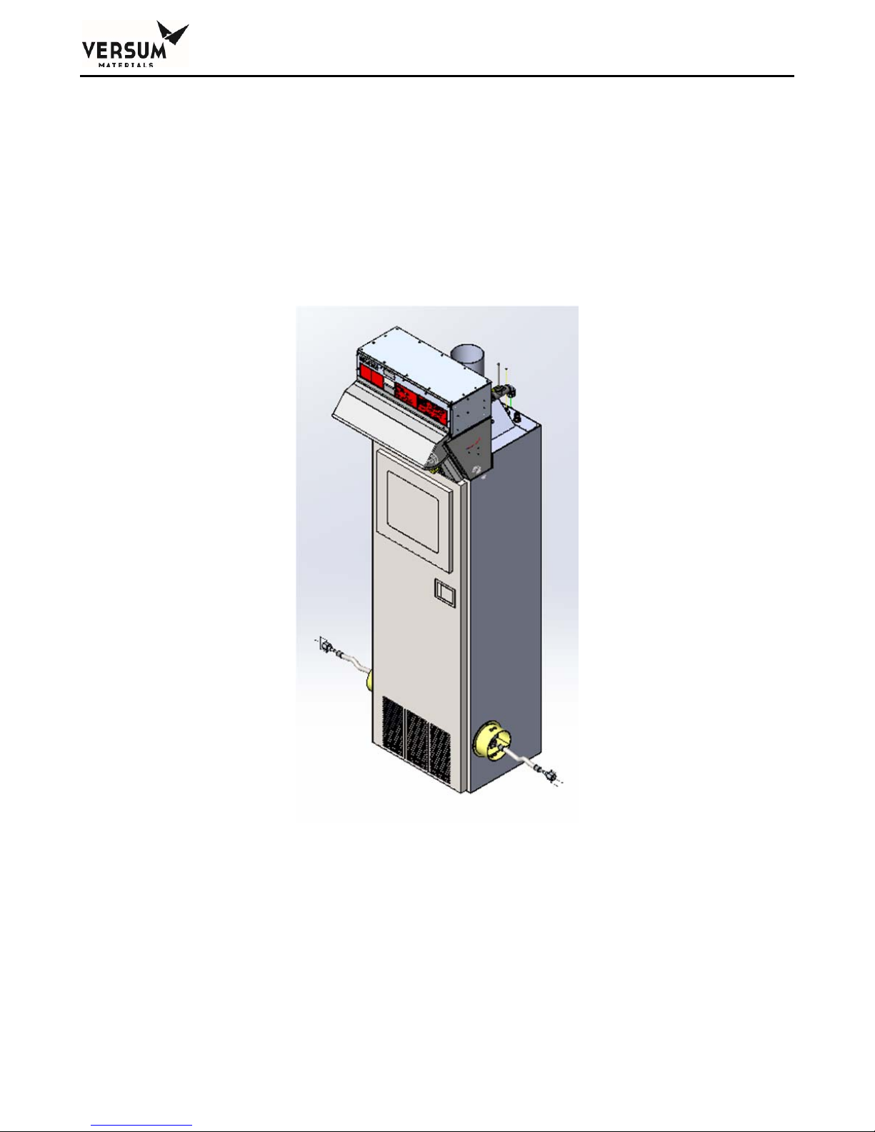
The BSGS eV / BULKGUARD eV module is shipped in a large wooden crate. When the crate
is delivered to the site, ensure that the shipping manifest properly documents the shipment. Verify that
the delivery date, time, and the item delivered are accurately shown on the shipping manifest. Look for
signs of any damage that may have occurred during shipment. Note on the bill of lading any manifest
discrepancies and any significant crate damage found. Alert your Versum Materials, Inc.
representative of any damage that has occurred.
2.0 Unpacking and Handling
The BSGS eV / BULKGUARD eV module is shipped inside a large box designed to protect the
unit from minor shipping damage. Extreme care should be taken in handling the large crate since the
equipment can be damaged if it is tipped on its side or dropped. The equipment should not be removed
from its crate until it has been moved by forklift to a location near its final installation area.
Approximate weight of the crated module is 700 lbs (320 kg).
_______________________________________________________________________________________________________________
MNL000530 Revision 1 03/15/2018
BSGS eV / BULKGUARD eV
© Versum Materials, Inc. as of the revision and date shown. All rights reserved.
Page 2 - 2
Confidential and Proprietary Data
Page 49

Chapter 2 - Installation
1. Once the module is moved to near its final location, remove the
walls and roof of the box.
Inspect the equipment for shipping damage.
The outside of the equipment cabinet should be checked for scratches, dents, or
damaged external piping.
The door of the module should be opened and the piping system should be carefully
inspected for damage.
The front door of the AP11 controller and eV ECC should be opened to check for
damaged electrical components.
NOTE: Any damage observed on the equipment must be immediately reported to the
shipping company and to the Versum Materials, Inc. factory.
2. Using a forklift, lift the equipment off the crate and carefully set it on the floor.
3. Move the unit to its final location.
3.0 Module Installation
All equipment must be installed in accordance with the following drawings and codes.
BSGS eV / BULKGUARD eV module drawings included in Appendix A – Installation Drawing
Package.
Seismic Codes per ASME, UBC, or applicable local codes.
NOTE: It is the responsibility of the owner to ensure that all equipment modules are
mounted in accordance with all applicable civil and seismic codes.
Additional considerations and notes:
1. BSGS eV / BULKGUARD eV modules and source containers (Y containers, Drums, Trailers,
etc.) must be sited per Code requirements and Versum Materials, Inc. criteria away from fire
and combustible sources. Contact your Versum Materials, Inc. representative for assistance
with siting criteria.
_______________________________________________________________________________________________________________
MNL000530 Revision 1 03/15/2018
BSGS eV / BULKGUARD eV
© Versum Materials, Inc. as of the revision and date shown. All rights reserved.
Page 2 - 3
Confidential and Proprietary Data
Page 50
Chapter 2 - Installation
2. An overhead roof or canopy is recommended for source vessels and BSGS eV / BULKGUARD
eV equipment. Although the equipment is designed to NEMA 3R, it is recommended that it is
protected against direct rain. It should also be noted that snow and ice accumulation could
make weight scale readings inaccurate. A roof overhead will also protect operators and the
container process connection during container changes in inclement weather.
3. The eV ECC located on top of the module should not be installed in direct sunlight. Heat from
solar gain is the primary reason for increased electrical enclosure temperature. Overexposure
to high temperature over time will reduce component longevity.
4. The mounting location for all equipment modules should be clean and level. It is recommended
that the equipment modules be placed on concrete pads prepared per applicable local codes.
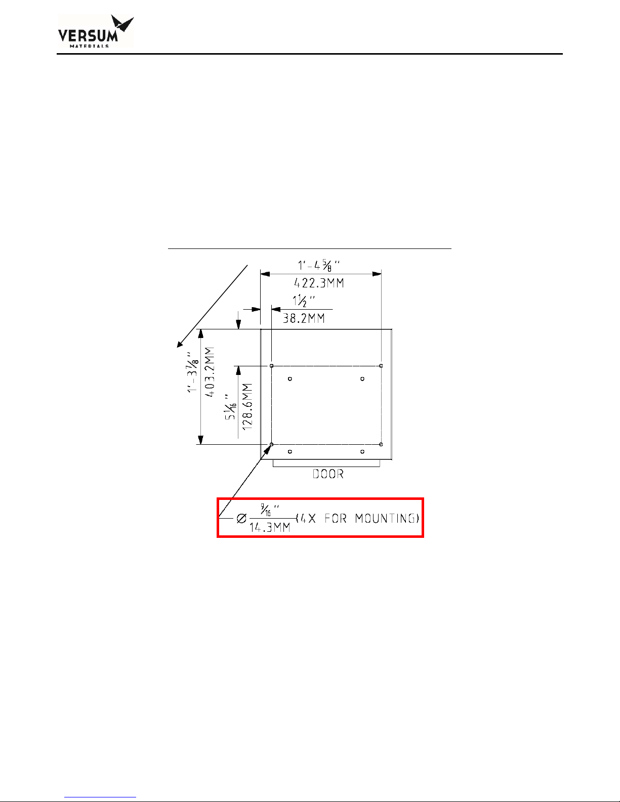
5. The floor outline dimensions and mounting hole locations are shown in Figure 2-1 below:
Figure 2-1. Rack Mounting Hole Locations in Floor
6. There shall be no obstructions in front of any access covers, including controller, electrical
enclosures, or piping cabinet.
7. Final equipment layout and mounting locations are the responsibility of the owner. It is
recommended that the process gas container be located to the back of the module to allow easy
access to the display and piping system components. See Appendix A – Installation Drawing
Package, BSGS eV / BULKGUARD eV Pigtail assembly installation drawings.
_______________________________________________________________________________________________________________
MNL000530 Revision 1 03/15/2018
Page 2 - 4
BSGS eV / BULKGUARD eV
© Versum Materials, Inc. as of the revision and date shown. All rights reserved.
Confidential and Proprietary Data
Page 51

Chapter 2 - Installation
8. If the painted surfaces of the enclosure cabinets are nicked or scratched during handling and
installation, they must be painted to prevent rust from forming. Touch up paint is not provided
with the equipment. Touch up paint must be purchased from a local paint supplier. The Paint
Specification is included in Chapter 3 - Module Specifications.
9. Supporting the source container piping and source container ventilation duct is the
responsibility of the owner. The piping should be supported to prevent the accidental opening
of the face seal connection. See Appendix A – Installation Drawing Package, BSGS eV /
BULKGUARD eV pigtail installation drawings for general routing and support information.
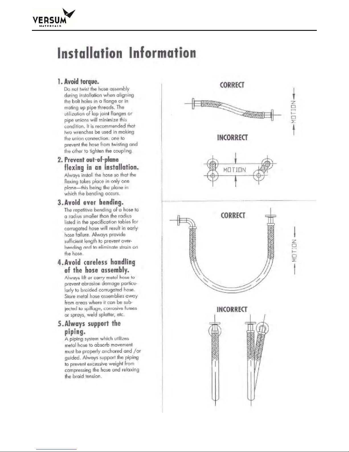
10. ½” process gas flex hoses supplied by Versum Materials, Inc. for approved gases, provide a
more forgiving means of connecting process gas piping to a source container with respect to
container location, but do have limitations. The following 2 pages are a list of those limitations
and recommendations for proper installation.
_______________________________________________________________________________________________________________
MNL000530 Revision 1 03/15/2018
BSGS eV / BULKGUARD eV
© Versum Materials, Inc. as of the revision and date shown. All rights reserved.
Page 2 - 5
Confidential and Proprietary Data
Page 52
Chapter 2 - Installation
_______________________________________________________________________________________________________________
MNL000530 Revision 1 03/15/2018
11.
Page 2 - 6
BSGS eV / BULKGUARD eV
© Versum Materials, Inc. as of the revision and date shown. All rights reserved.
Confidential and Proprietary Data
Page 53
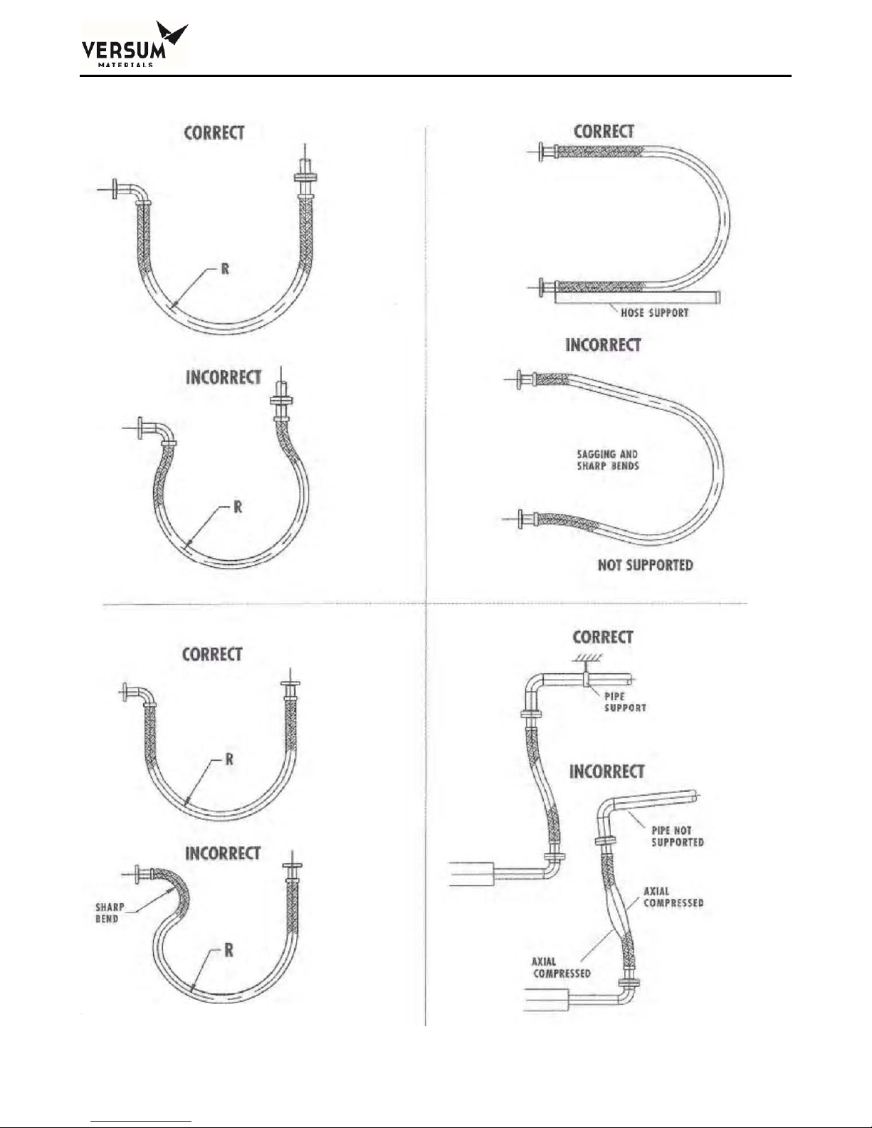
Chapter 2 - Installation
_______________________________________________________________________________________________________________
MNL000530 Revision 1 03/15/2018
BSGS eV / BULKGUARD eV
© Versum Materials, Inc. as of the revision and date shown. All rights reserved.
Page 2 - 7
Confidential and Proprietary Data
Page 54

Chapter 2 - Installation
FlexHoseSpecifications
Nominal
Diameter
(inches)
1/2 12 1 0.79 1.34 2973 6104 0.24
Actual
I.D.
(mm)
Number
of
Braids
Nominal
O.D.
(inches)
Minimum
Bend
Radius
(inches)
Maximum
Working
Pressure@
70degF
(psig)
Burst
Pressure@
70degF
(psig)
Weightper
foot
(lbs.)
4.0 Piping Connections
All tubing connections to the module should be designed and installed following all local piping codes
and should comply with the intent of ASME B31.3 "Chemical Plant and Petroleum Refinery Piping."
Tubing must be sized to flow the maximum amount of gas required by the process system. Tubing is
normally constructed of 316L stainless steel, but is Hastelloy C-22 on Hydrogen Chloride (HCl)
modules.
All piping must be installed in accordance with the installation drawings located in Appendix A of this
manual.
Connection Points
All tubing connections are made at either the top rear of the module or within the source inlet cutouts
located on the lower sidewalls of the module. All tube ends have been faced and are ready for welding
to facility piping. Welding should be performed using established high purity welding techniques.
Verify all tubing connections with the flow schematic, or installation drawing prior to welding.
Piping connection points for each piece of equipment can be found in the drawings located in
Appendix A of this manual.
Process piping connections are double bagged and taped at the factory prior to shipment. Vent piping
connections are single bagged and taped. Tube ends have been faced and are ready for welding.
_______________________________________________________________________________________________________________
MNL000530 Revision 1 03/15/2018
BSGS eV / BULKGUARD eV
© Versum Materials, Inc. as of the revision and date shown. All rights reserved.
Page 2 - 8
Confidential and Proprietary Data
Page 55
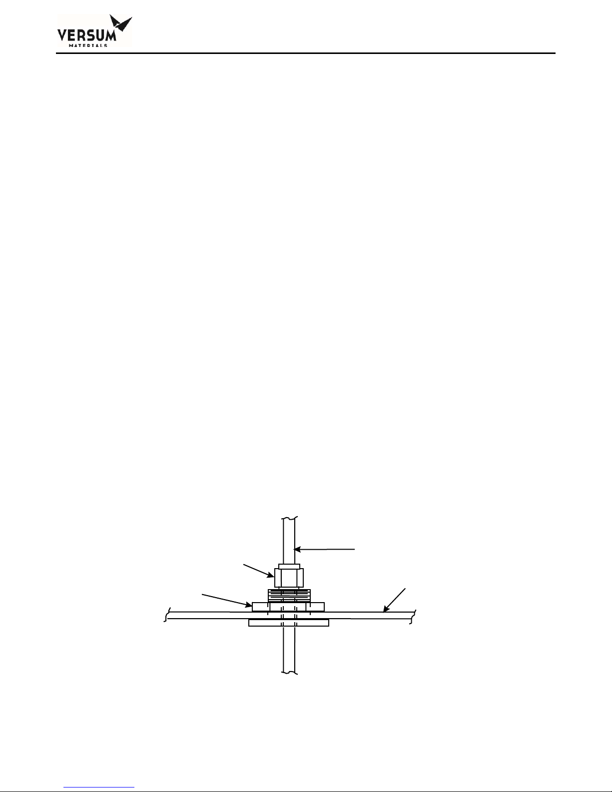
Chapter 2 - Installation
N
Depending on the configuration, the following facility tubing connections may be supplied with a
module:
Process outlet A: 1/2" (12.7 mm) diameter, 0.049" (1.2 mm) wall thickness
Optional coax 3/4" (19 mm) diameter, 0.065” (1.6 mm) wall thickness
Process outlet B/C/D (opt): 1/2" (12.7 mm) diameter, 0.049" (1.2 mm) wall thickness
Optional coax 3/4" (19 mm) diameter, 0.065” (1.6 mm) wall thickness
NOTE – Optional process C and D are shipped with external open-ended piping spools
installed to provide stability during shipment. These process lines must be capped if they are
not facilitated at the customer site.
Purge and High Pressure Leak Check (HPLT) Gas Inlet:
1/4" (6.4 mm) diameter, 0.035" (0.9 mm) wall thickness
Venturi inlet: 1/4" (6.4 mm) diameter, 0.035" (0.9 mm) wall thickness
Vent outlet: 3/8" (9.5 mm) diameter, 0.035" (0.9 mm) wall thickness
Bonnet Vent outlet (up to four lines):
1/4" (6.4 mm) diameter, 0.035" (0.9 mm) wall thickness
Enclosure Exhaust: 6" (152.4 mm) outside diameter duct
Pneumatics and Z-Purge: ¼” (6.3 mm) outside diameter compression fitting.
The process line connections can be furnished in one of two configurations: Standard Bulkhead or
Coaxial Bulkhead. All other connections, such as purge, Venturi inlet, and vent, will be furnished with
standard bulkheads.
The standard bulkhead permits a single process out line to penetrate the enclosure, while providing an
acceptable seal for enclosure ventilation purposes. Figure 2-2 shows a standard bulkhead.
Compression Fitting
Grips OD of Tube
ut
_______________________________________________________________________________________________________________
MNL000530 Revision 1 03/15/2018
Page 2 - 9
BSGS eV / BULKGUARD eV
© Versum Materials, Inc. as of the revision and date shown. All rights reserved.
1/2 TOD Gas Line
Continuous (Passes Through
Bulkhead)
Cabinet Top
Figure 2-2. Standard Bulkhead
Confidential and Proprietary Data
Page 56
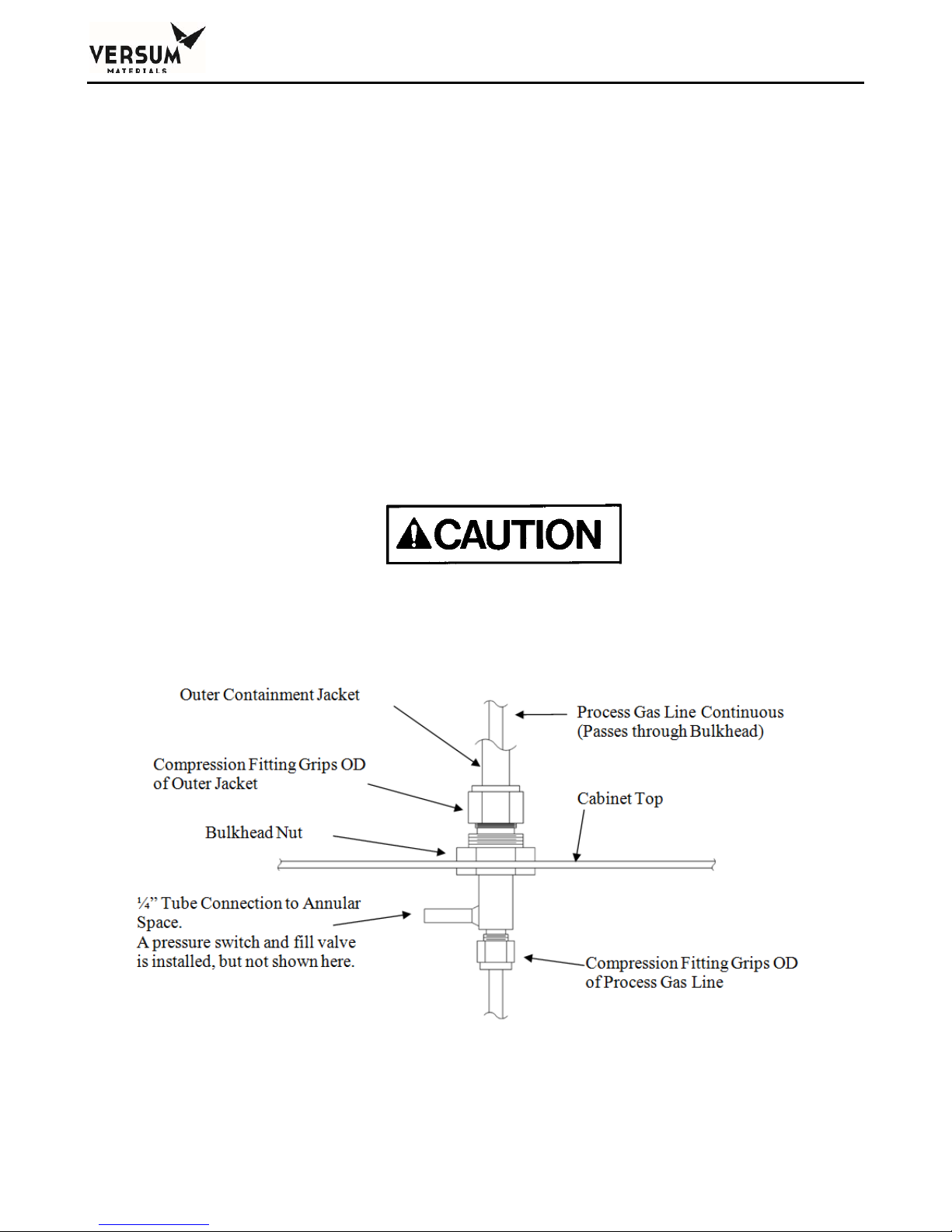
Chapter 2 - Installation
The optional coaxial bulkhead permits a single process out line to penetrate the enclosure, while
providing an acceptable seal for enclosure ventilation purposes. In addition, the coaxial bulkhead
provides a termination point for an outer secondary containment tube. The outer secondary
containment tube, or jacket, is connected directly to the coaxial bulkhead. The outer secondary
containment continues through the coaxial bulkhead and terminates as a branch on the coaxial
bulkhead inside the enclosure.
On the branch of the coaxial bulkhead inside the enclosure, a pressure switch and manual isolation
valve is installed to facilitate the fill and monitoring of the coaxial annular space. The pressure decay
technique is used for coaxial annular space monitoring and requires the annular space to be pressurized
with inert gas (typically nitrogen) above the pressure switch setpoint, in this case, 120 psig. If a leak
develops to atmosphere from the coaxial jacket, an alarm displays on the controller, identifying the
coaxial jacket that is leaking. Similarly, if a leak develops from the process pipe into the coax annular
space, the same alarm displays on the controller identifying the coaxial jacket that is leaking. Figure 23 shows a coaxial bulkhead.
For coax tubing on silane lines, the pressure decay method with an inert gas (NOT AIR)
must be used.
Figure 2-3. Coaxial Bulkhead (optional)
_______________________________________________________________________________________________________________
MNL000530 Revision 1 03/15/2018
BSGS eV / BULKGUARD eV
© Versum Materials, Inc. as of the revision and date shown. All rights reserved.
Page 2 - 10
Confidential and Proprietary Data
Page 57

Chapter 2 - Installation
Vent Lines
Vent lines must be piped to a safe location away from personnel exposure per owner site requirements.
The vent discharge opening should be constructed to prevent blockage from weather and animals. Vent
gases will be introduced into the vent line during routine purging cycles.
If treatment is required in order to abate the process gas, the vent line must be piped directly to an
acceptable pollution abatement system designed for the specific gas being vented. Process gas will be
introduced into the vent line during the "Pre-Purge" and “Post-Purge” sequences, when the process gas
pigtail is being purged prior to process gas cylinder removal and following gas removal, respectively.
At this time, 106-127 CFH (50-60 LPM) of nitrogen is also being sent into the line through the vacuum
Venturi loop. The purging sequences typically run approximately 30-45 minutes. Process gas is also
introduced during the
following the post-purge sequence and prior to on-line mode.
During a container change, it can be expected that the following masses of gas will be vented from a
BSGS eV / BULKGUARD eV module:
Pre-purge operating sequence: Total process gas mass vented:
Pre-purge operating sequence. Total mass of N2 vented:
Cylinder change sequence HPLT. Total mass of 10% He/N2 mix vented = 0.2 lb.
Post purge operating sequence. Total mass of N
_______________________________________________________________________________________________________________
MNL000530 Revision 1 03/15/2018
BSGS eV / BULKGUARD eV
Page 2 - 11
“Conditioning” sequence where process gas is cycled through the pigtail,
0.1 lb. SiH
0.1 lb. NH3
0.2 lb. NF3
0.1 lb. N2O
0.1 lb. HCl
0.1 lb. CO2
SiH4 requires 120 purge cycles, 2.4 lb.
NH3 requires 90 purge cycles, 1.8 lb.
NF3 requires 75 purge cycles, 1.5 lb.
N2O requires 75 purge cycles, 1.5 lb.
HCl requires 90 purge cycles, 1.8 lb.
CO
requires 75 purges cycles, 1.5 lb.
2
SiH
requires 120 purge cycles, 2.4 lb.
4
NH3 requires 90 purge cycles, 1.8 lb.
NF
requires 75 purge cycles, 1.5 lb.
3
N2O requires 75 purge cycles, 1.5 lb.
HCl requires 90 purge cycles, 1.8 lb.
CO2 requires 75 purges cycles, 1.5 lb.
© Versum Materials, Inc. as of the revision and date shown. All rights reserved.
4
vented.
2
Confidential and Proprietary Data
Page 58
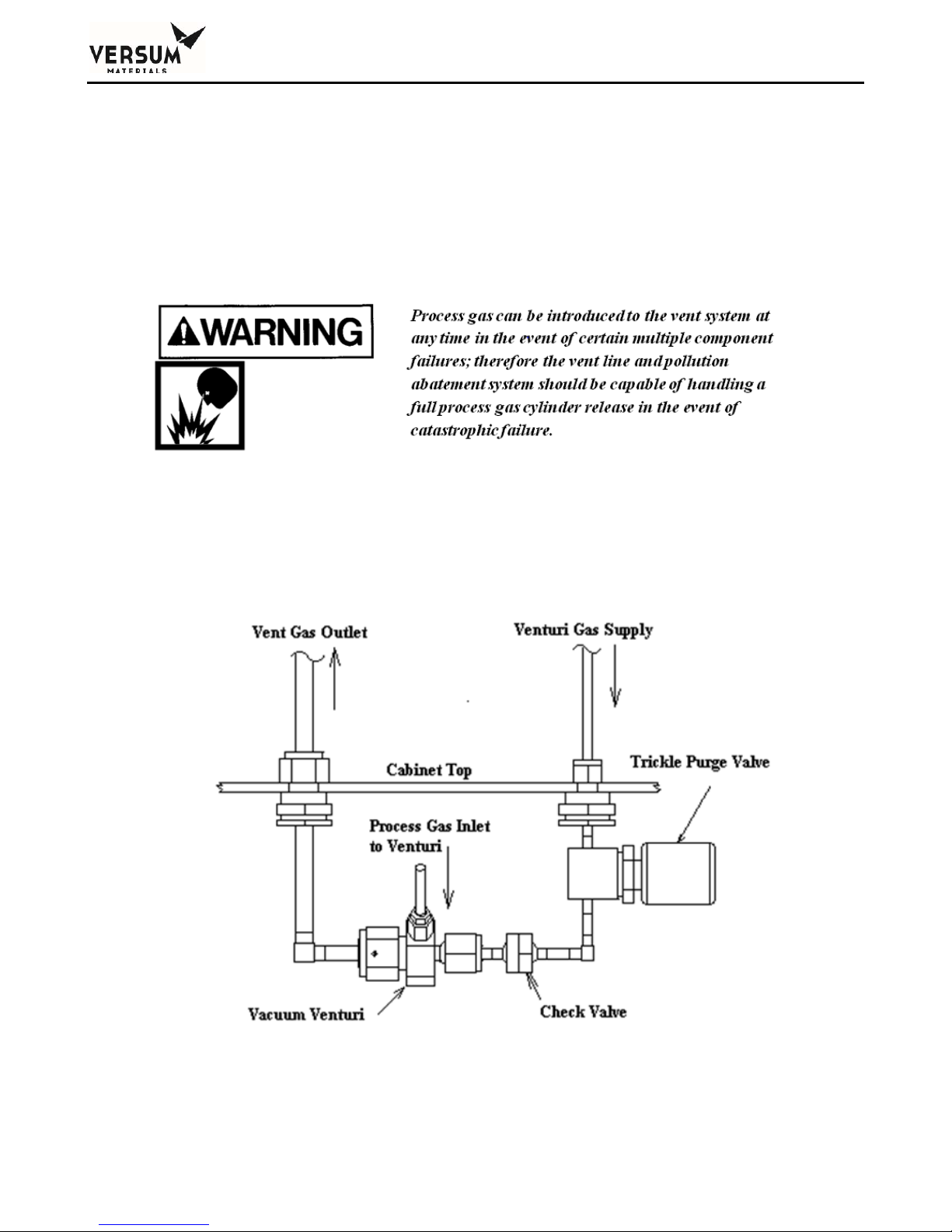
Chapter 2 - Installation
Condition operating sequence. Total mass vented during 5 conditioning cycles is:
4 lb. SiH4
0.2 lb. NH3
2
3
O
6 lb. NF
8 lb. N
7 lb. HCl
8 lb. CO2
A nitrogen trickle purge is constantly bled into the vent line to maintain an inert atmosphere when
hazardous gases are being used. For this reason, a trickle purge valve is furnished with a trickle purge
orifice. The flow rate of this trickle purge is approximately 4-10 CFH (2-5 LPM). The module
employs a vacuum Venturi module that integrates a vacuum Venturi, check valve, and trickle purge
valve into a single unit. Figure 2-4 depicts a typical trickle purge assembly that isn’t integrated into a
module for clarity.
Figure 2-4. Typical Trickle Purge Assembly
_______________________________________________________________________________________________________________
MNL000530 Revision 1 03/15/2018
BSGS eV / BULKGUARD eV
© Versum Materials, Inc. as of the revision and date shown. All rights reserved.
Page 2 - 12
Confidential and Proprietary Data
Page 59

Chapter 2 - Installation
Versum Materials, Inc. strongly recommends a separate Venturi supply source rather than a
houseline source. Most process cylinder pressures are significantly higher than houseline operating
pressures. If multiple failures of certain process panel components occur, there is a remote possibility
of back contamination of the houseline source connected to the vacuum Venturi.
When multiple gases are to be vented, ensure compatibility before plumbing vents together. Contact
your Versum Materials, Inc. representative for this information.
The Venturi line requires 80-90 psig (5.5-6.2 barg) of nitrogen to adequately produce the vacuum
needed during purge cycles. The supply is usually taken from a bulk liquid source, but it can also
originate from a cylinder manifold system. The vacuum generator will demand a flow of 106-127
CFH (50-60 LPM) of nitrogen during purge cycles.
Vacuum Venturi Vent Line Sizing
The vacuum Venturi is extremely susceptible to vent line back pressure and cannot tolerate more
than 0.5 psi back pressure. If back pressure exceeds 0.5 psi, the AP11 controller will fail and abort
the purge sequence on insufficient vacuum. It will be impossible to continue until the restriction is
eliminated. The recommended vent line sizes below should be used when installing the vacuum
Venturi vent line. Transitions to larger tubing should be made within 1 ft. of the piping enclosure.
Recommended Vent Line Sizes:
Line Length Minimum Recommended Tube Diameter
1 ft. through 5 ft. 1/2" tube
5 ft. through 100 ft. 3/4" tube
100 ft. through 400 ft. 1" tube
Over 400 ft. 1-1/2" tube
The Venturi vent line must be piped to a safe location away from personnel exposure. It is
recommended that the customer consult and design the vent system to all applicable codes. The
emergency vent discharge opening should be constructed to prevent blockage from weather and
animals. Vent gases will be introduced into the emergency vent lines whenever a purge or conditioning
sequence is run. Do not combine vent lines, instead, route individual vent lines to an appropriately
sized vent header.
_______________________________________________________________________________________________________________
MNL000530 Revision 1 03/15/2018
BSGS eV / BULKGUARD eV
© Versum Materials, Inc. as of the revision and date shown. All rights reserved.
Page 2 - 13
Confidential and Proprietary Data
Page 60
Chapter 2 - Installation
Bonnet Vent Line
The Bonnet Vent must be kept open to allow gas to escape. It must not be sealed or routed into other
vent lines. The bonnet vent discharge opening should be constructed to prevent blockage from
weather, animals, and insects, but not prevent gas from escaping. If the standard outlet location is
directed in an unsafe manner (i.e. towards flammable construction materials, personnel walkways, etc.)
or presents another potentially unsafe situation the outlet must be rerouted to a safe location during
installation. Gas detectors and/or UV/IR detectors should be used in the surrounding area to monitor
for a potential leak.
Purge and High Pressure Leak Check (HPLT) Supply Line
The purge and HPLT supply line must be connected to a dedicated purge source, and leak check
source. The pressure required during cylinder purging is 80-90 psig (5.5-6.2 barg). An HPLT pressure
of 950-965 psig (65.5-66.5 barg) is required for silane (SiH4), nitrous oxide (N2O), nitrogen trifluoride
(NF3), hydrogen chloride (HCl), and carbon dioxide (CO2) process gases. For ammonia (NH3) process
gas, an HPLT pressure of 190-205 psig (13.1-14.1 barg) is required. Sufficient over pressure
protection must be provided. Versum Materials, Inc. recommends a safety relief valve set at a
maximum of 200 psig (13.8 barg) for the purge supply, and safety relief valve set at a maximum of
1200 psig (82.7 barg) for silane (SiH4), nitrous oxide (N2O), nitrogen trifluoride (NF3), hydrogen
chloride (HCl), and carbon dioxide (CO2) HPLT supply. For ammonia (NH3) process gas, a safety
relief valve set at a maximum of 250 psig (82.7 barg) is required. If a purge module has been
purchased from Versum Materials, Inc., relief devices will be included.
Purge and High Pressure Leak Check (HPLT) Backflow Prevention
All Purge and High Pressure Leak Check (HPLT) system must include backflow prevention in the
form of a check valve. This will prevent process gas from migrating back into the purge panels and
piping.
Enclosure Exhaust
Many BSGS eV / BULKGUARD eV modules are supplied with process piping inside an exhausted
enclosure. Modules that have been configured with a ventilation flow switch (a pitot tube will be
located inside the 6” vent stack), will require 200 CFM (5663 LPM) exhaust ventilation and -0.1” (-.25
mm) water column static pressure by the customer, whether located indoors or outdoors.
_______________________________________________________________________________________________________________
MNL000530 Revision 1 03/15/2018
BSGS eV / BULKGUARD eV
© Versum Materials, Inc. as of the revision and date shown. All rights reserved.
Page 2 - 14
Purge gas sources used for the BSGS eV / Bulkguard eV must
not be shared with other BSGS eV / Bulkguard eV modules if
the gas types are incompatible. Purge gas must not be supplied
from a low pressure bulk gas source.
Confidential and Proprietary Data
Page 61

Chapter 2 - Installation
With the exception of nitrous oxide (N2O), modules with exhausted enclosures that haven’t been
configured with a ventilation flow switch are for inert gases, and don’t require exhaust ventilation if
located outdoors. In this case, the 6” (152.4 mm) diameter duct at the top of the piping enclosure may
be capped. If, however, the enclosure will be located indoors, it is recommended that the enclosure be
ventilated at 75 CFM (2124 LPM) minimum. Ifexhaust ventilation is not provided for indoor inert
modules (enclosure or open-air rack), then Versum Materials, Inc. recommends that forced mechanical
ventilation be provided for the room per local code or regulatory requirements. A typical room
ventilation requirement for indoor inert gas systems is to provide room ventilation at 6 air changes per
hour, or 1 CFM/ft.2 (2.6 LPM/meter2) of floor space, whichever is smaller. Also, customers should
determine if additional safeguards are warranted, such as room O2 monitoring with local and remote
alarms on low O
concentration (i.e. less than 19.5% O2 detected in the room).
2
Nitrous oxide (N
O) modules equipped with exhausted enclosures must be ventilated to 75 CFM (2124
2
LPM) minimum whether located indoors or outdoors to extract excess heat generated by the JT heater.
Silane (SiH4) modules are supplied without an exhausted enclosure and must be located outdoors.
Heat Trace and Insulation
All source containers that are heated (including Y containers, drums, tonners, and ISO containers)
must have heat trace and insulated piping at least from the source container to the process regulators.
If the source container is heated and the piping isn’t maintained at the same temperature, liquefaction
can occur and create operational problems up to and including a module shutdown. Heat trace and
insulation may also be required for the houseline, from the process regulator to the facility entrance,
depending on ambient temperature. If in doubt, consult your Versum Materials, Inc. representative.
If the BSGS eV / BULKGUARD eV module has been ordered with source heater capability, panel
heat trace and insulation will have been partially installed at the factory. The module is shipped with a
bag of pre-cut, short black insulating material. This insulation is to be field installed over the piping
VCR joints AFTER the joints are field pressure and leak tested.
Depending upon the module configuration, inlet flex hoses may also be factory heat traced and
insulated. If the pigtail is field piped, then the customer is responsible for installing heat trace and
insulation from the DISS connection to the module. The heat trace will be supplied by the factory,
coiled at the pigtail inlet to the piping cabinet but acquiring and installing the insulation (as per the
installation drawings in Appendix A) will be customer scope.
Heat trace installation details are called out in the electrical installation drawing, located in Appendix
A of this manual. Versum Materials, Inc. recommends ½” Buna-N/PVC rubber insulation for all field
installed insulation.
NOTE: Field-installed heat trace and insulation should be installed after the pipeline has been pressure
and leak tested.
_______________________________________________________________________________________________________________
MNL000530 Revision 1 03/15/2018
BSGS eV / BULKGUARD eV
© Versum Materials, Inc. as of the revision and date shown. All rights reserved.
Page 2 - 15
Confidential and Proprietary Data
Page 62

Chapter 2 - Installation
If additional heat trace is required in the field, the recommended material is Delta-Therm PT3SB Heat
Trace Cable. This cable is constant-Watt (12 watts /ft at 240 VAC), so a controller will need to be
installed to regulate heat trace temperature. Versum Materials, Inc. does not recommend selfregulating heat trace because heat trace temperature cannot be changed if process conditions change.
Piping System Testing
Prior to the electrical start-up of the system, all field installed process piping should be tested. Factory
installed piping has been tested prior to shipment and is shipped under positive Argon pressure. Verify
that the Argon pressure has been maintained at greater than or equal to 15 psig (1 bar g). If positive
pressure has not been maintained, contact the Versum Materials, Inc. representative.
It is also recommended that the module be pressure and leak tested before process gas is introduced.
VCR joins may have loosened during shipment. MAWP of the piping systems within the module are
as follows:
High pressure process piping, from PT-1 to PCV-1, purge inlet CV-9/CV4 to V-13, and
V-13 to MV29.
o Process gases: Silane (SiH
), nitrous oxide (N2O), nitrogen trifluoride (NF3), and
4
carbon dioxide (CO2): 3000 psig MAWP.
o Process gases: Hydrogen chloride (HCl): 1300 psig MAWP.
o Process gases: Ammonia (NH
): 250 psig MAWP.
3
o Other gases: contact your Versum Materials, Inc. representative
Low pressure process piping from PCV-1 to MV-38.
o Process gases: All: 250 psig MAWP.
After all the piping joints have passed the pressure and leak tests, install the factory supplied pre-cut,
short black insulating material over the VCR joints. If the bag has been misplaced, ½” thick flexible
Buna-N/PCV clamshell foam rubber insulation can be purchased by the installer locally.
_______________________________________________________________________________________________________________
MNL000530 Revision 1 03/15/2018
BSGS eV / BULKGUARD eV
© Versum Materials, Inc. as of the revision and date shown. All rights reserved.
Page 2 - 16
Confidential and Proprietary Data
Page 63

Chapter 2 - Installation
5.0 Elecrical and Pneumatic Connections
All electrical connections must comply with Article 300 - Wiring Methods and Article 500 Hazardous (Classified) Locations of the National Electric Code (NEC), and NFPA 70 if installed in the
United States. Reference to the use of this equipment in Hazardous Locations only applies to
installations located within the United States of America. BSGS eV / BULKGUARD eV modules are
designed for use in Explosive Atmosphere Directive (ATEX) locations.
All electrical and pneumatic connections and lines must be installed in accordance with the following
drawings.
“Electrical Details for Typical Installation” located in Appendix A.
“Installation, BSGS eV / BULKGUARD eV Rack” located in Appendix A.
Sealing hubs and low point drains and other means of providing a watertight seal shall be utilized for
outdoor installations. It is also recommended to use poured seals and nitrogen purge for outdoor
applications to minimize effects of moisture on the controller. Additional specifications will have to
be followed for installation within electrically classified areas.
Grounding Method
The equipment must be grounded in accordance with Article 250 - Grounding in the National
Electrical Code, if installed in the United States. The customer is responsible for connections to earth
ground. A ground connection is supplied in the controller for this purpose.
On the plenum of the gas cabinet there is an additional split bolt terminal for connection hookup to the
facilities grounding network. Figure 2.5 shows a suggested grounding method for a typical system.
This drawing may not be applicable to your specific system.
_______________________________________________________________________________________________________________
MNL000530 Revision 1 03/15/2018
BSGS eV / BULKGUARD eV
© Versum Materials, Inc. as of the revision and date shown. All rights reserved.
Page 2 - 17
Confidential and Proprietary Data
Page 64
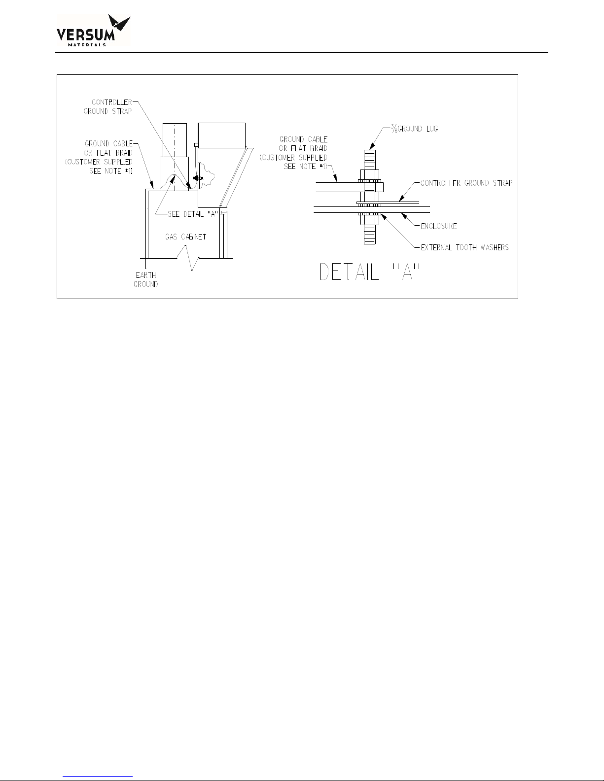
Chapter 2 - Installation
p
NOTE 1: USE #4 AWG (25 mm) WIRE FOR NON-EMI/RFI SYSTEMS.
USE ALPHA #1239, 1-3/8” (35 mm) FLAT BRAID OR EQUIVALENT FOR EMI/RFI
PROTECTED SYSTEMS. TOTAL LENGTH NOT TO EXCEED 10’ –0” (3 M).
eVECC
tional)
(o
AP11
Figure 2.5: Suggested Grounding Method
Use of #4 AWG ground wire will not maintain CE marking. Use Alpha #1239, 1-3/8” flat braid or
equivalent for CE marked systems (total length not to exceed 10 feet or 3 meters).
After grounding the overall resistance must be measured. This resistance for the equipment ground to
the grounding electrode should not exceed one ohm (1). Check the effectiveness of grounding by
using a ground resistance meter (i.e., an AEMC clamp on ground resistance tester or equivalent).
Power Supply Connection – AP11 with eV ECC
BSGS eV / BULKGUARD eV modules are normally equipped with an eV ECC located on top of the
AP11 controller. When equipped with an eV ECC, the BSGS eV / Bulkguard eV has two power feed
options: single feed (both AP11 and eV ECC powered by a single feed) and dual feed (AP11 and eV
ECC powered by separate feeds). Details of the termination points are shown in the electrical
installation drawing, Appendix A of this manual.
Each BSGS eV / BULKGUARD® eV system should be installed with an independent external circuit
interrupting device to remove power from the unit when maintenance on the controller is required and
should be Lockout/Tagout capable. This device should be rated as a minimum at 240 volts, 40 amps,
50/60 Hz and 10,000 rms symmetrical ampere interrupting capacity. The device should be accessible
to the operators, marked as the disconnecting device for the gas cabinet, and must have the on/off
position clearly marked for the operator, and should be near the gas cabinet.
Disconnect switches shall meet the requirements of IEC 60947-1 and IEC 60947-3 and the disconnect
switch must not interrupt the protective earth conductor.
_______________________________________________________________________________________________________________
MNL000530 Revision 1 03/15/2018
Page 2 - 18
BSGS eV / BULKGUARD eV
© Versum Materials, Inc. as of the revision and date shown. All rights reserved.
Confidential and Proprietary Data
Page 65
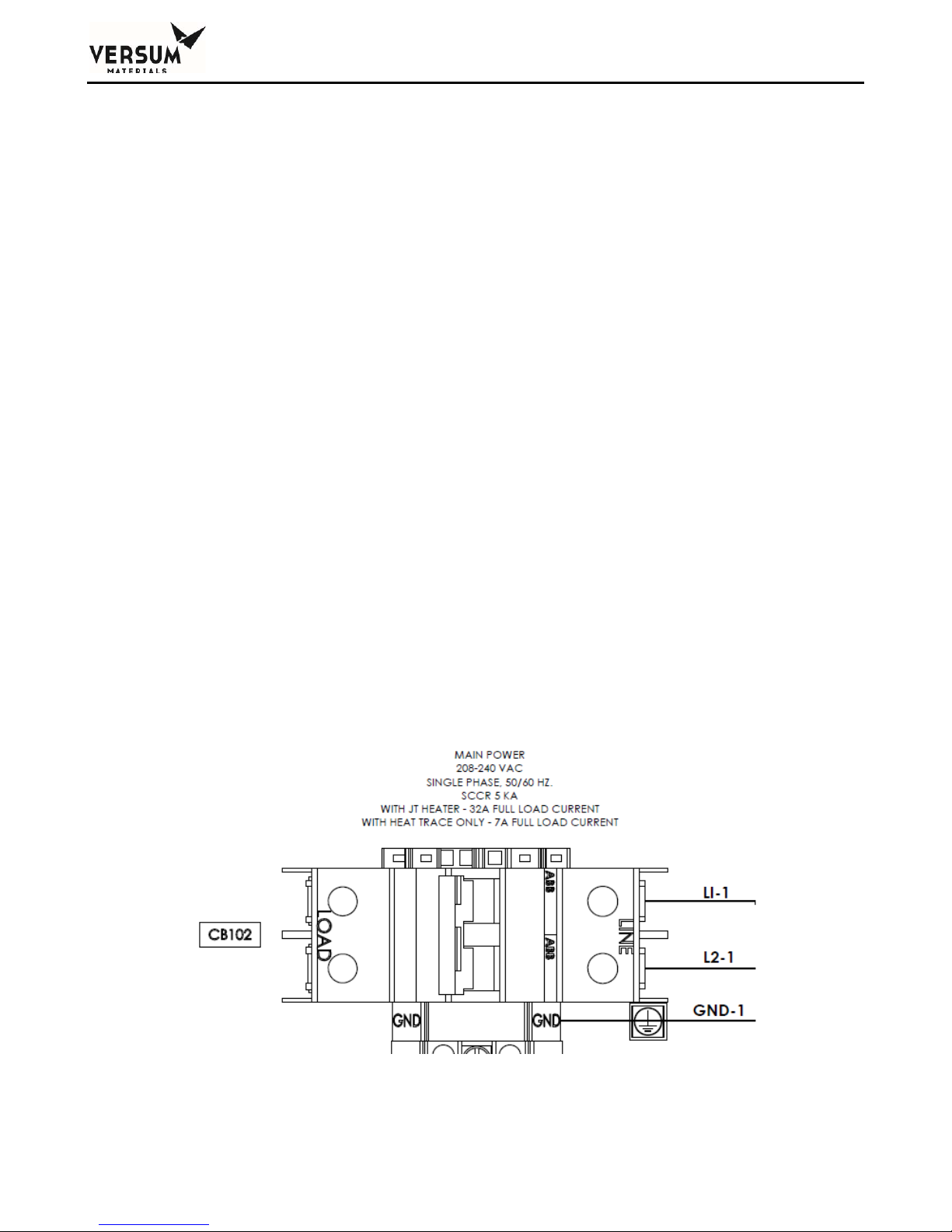
Chapter 2 - Installation
Power Requirements: Single Power Feed – JT heater with heat trace
208-240 VAC, 32A, 50/60Hz, 3 wire
Power Requirements: Single Power Feed – Heat trace with no JT heater
208-240 VAC, 7A, 50/60Hz, 3 wire
Power Requirements: Controller Powered Separate – JT heater with heat trace
Heaters: 208-240 VAC, 32A, 50/60Hz, 3 wire
Controller: 100-240 VAC @ 150 VA maximum, 50/60Hz, 3 wire
Power Requirements: Controller Powered Separate – Heat trace with no JT heater
Heaters: 208-240 VAC, 7A, 50/60Hz, 3 wire
Controller: 100-240 VAC @ 150 VA maximum, 50/60Hz, 3 wire
Acceptable wire gauge:
Single power feed: 14-4 AWG
OR
Heater Power: 14-4 AWG
Controller Power: 14-10 AWG
Use at least 75C rated wiring for the mains supply.
Replaceable fuses:
F1, F2, F3, and F4, located on the power board in the top of the AP11 controller, are 4A super
quick acting fuses.
FS-405, located in the eV ECC adjacent the DC power supply, is a 2A medium time delay fuse.
FS-406, FS-407, and FS-408 are 500 mA medium time delay fuses.
See the Spare Parts List in Appendix B for Manufacturer and part numbers and specifications.
_______________________________________________________________________________________________________________
MNL000530 Revision 1 03/15/2018
BSGS eV / BULKGUARD eV
© Versum Materials, Inc. as of the revision and date shown. All rights reserved.
Page 2 - 19
Figure 2-6: Power Connections
Confidential and Proprietary Data
Page 66
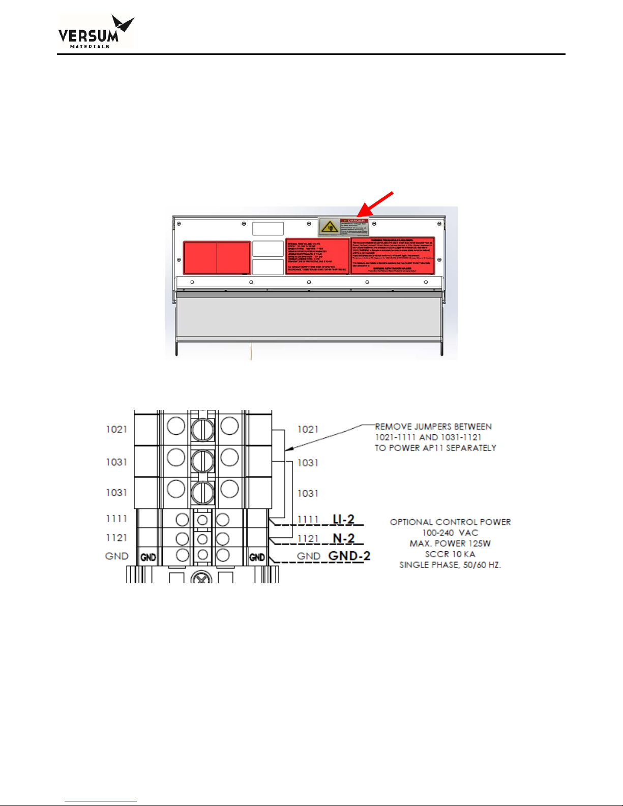
Chapter 2 - Installation
Dual Power Supply Connection:
To supply power for the AP11 controller separate from the heaters complete the following
steps: Remove wires between terminal blocks 1031-1121 and 1021-1111 (Figure 2-8).
Wire heater power feed into the normal connection points (CB-102 and adjacent ground block).
Wire controller power feed into terminal blocks 1092 (L1), 1102 (L2/N), and adjacent ground
block.
Apply “Danger – Hazardous Voltage Fed by Two Sources” label to controller door as shown
(Figure 2-7).
Figure 2-7: Label Placement
Figure 2-8: Wire Removal
_______________________________________________________________________________________________________________
MNL000530 Revision 1 03/15/2018
BSGS eV / BULKGUARD eV
© Versum Materials, Inc. as of the revision and date shown. All rights reserved.
Page 2 - 20
Confidential and Proprietary Data
Page 67

Chapter 2 - Installation
Power Supply Connection – AP11 controller only
There are some cases where the eV ECC will not be installed on the BSGS eV / BULKGUARD eV,
such as when neither a JT heater not heat trace are specified. In those cases, there will only be an
AP11 controller that requires power.
Each BSGS eV / BULKGUARD® eV system should be installed with an independent external circuit
interrupting device to remove power from the unit when maintenance on the controller is required and
should be Lockout/Tagout capable. This device should be rated as a minimum at 240 volts, 4 amps,
50/60 Hz and 10,000 rms symmetrical ampere interrupting capacity. The device should be accessible
to the operators, marked as the disconnecting device for the gas cabinet, and must have the on/off
position clearly marked for the operator, and should be near the gas cabinet.
Disconnect switches shall meet the requirements of IEC 60947-1 and IEC 60947-3 and the disconnect
switch must not interrupt the protective earth conductor.
The power input must be wired to the terminals shown below in Figure 2-9.
Figure 2-9: Dual Power Supply Terminal Connection
The power requirements are as follows:
100-240 VAC @ 150 VA maximum, 3 wire
Full load current - 4 amps
The controller power is the same for idle, average, and peak and is less than 0.125 KW.
_______________________________________________________________________________________________________________
MNL000530 Revision 1 03/15/2018
BSGS eV / BULKGUARD eV
© Versum Materials, Inc. as of the revision and date shown. All rights reserved.
Page 2 - 21
Confidential and Proprietary Data
Page 68
Chapter 2 - Installation
NOTE: Power wiring must be sized to deliver the required voltage at the rated
current. Voltages should be checked at each cabinet after installation to ensure
proper levels. Wire size should not exceed 12AWG (3.3 mm2). An optional kit is
available to allow use of 10AWG (5.26 mm2) wire.
Replaceable fuses - F1, F2, F3, and F4 located on the power board are 4A super quick acting fuses. See
the Spare Parts List in Appendix B for Manufacturer and part number specifications.
Use at least 75C rated wiring for the mains supply.
Field Connections
In NEC Class I, Division 2 areas (only in the U.S.A.),
a conduit seal ("pour fitting") or equivalent must be
installed between each electrical connection point on
the cabinet and the electrical source. Liquid tight
flexible conduit can be installed between the
GASGUARD® AP11 connectors and the conduit seals
to facilitate these connections. A maximum length of
18" (457 mm) is allowed between the last pour fitting
and the cabinet connector. All conduits shall be
sealed in accordance to Sections 501-5, 502-5 or 50470 of the National Electric Code. See Figures 2-10, 211, 2-12, and 2-13 for details.
NOTE: For Systems approved for installation and
use in Explosive Atmospheres (Europe), refer to
section 4.8 for additional instructions.
In classified hazardous areas – Do not separate
electrical terminations or connectors while energized
due to risk of electrical arc or spark which can ignite
potentially flammable atmospheres.
_______________________________________________________________________________________________________________
MNL000530 Revision 1 03/15/2018
BSGS eV / BULKGUARD eV
© Versum Materials, Inc. as of the revision and date shown. All rights reserved.
Page 2 - 22
Confidential and Proprietary Data
Page 69
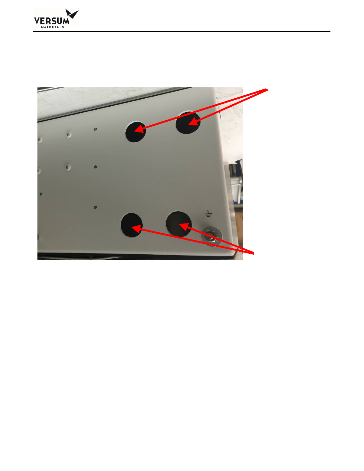
Chapter 2 - Installation
Systems which have been equipped with the eV ECC have conduit holes in the back of the sheet metal.
These conduit locations are shown in Figure 2-10 and Figure 2-11.
All conduit holes are 1-1/8" (28.6 mm) in diameter for 3/4" conduit.
Power Conduit
Customer I/O and
Ethernet
Figure 2-10: Rear View of GASGUARD® eV AP11 Controller
_______________________________________________________________________________________________________________
MNL000530 Revision 1 03/15/2018
BSGS eV / BULKGUARD eV
© Versum Materials, Inc. as of the revision and date shown. All rights reserved.
Page 2 - 23
Confidential and Proprietary Data
Page 70
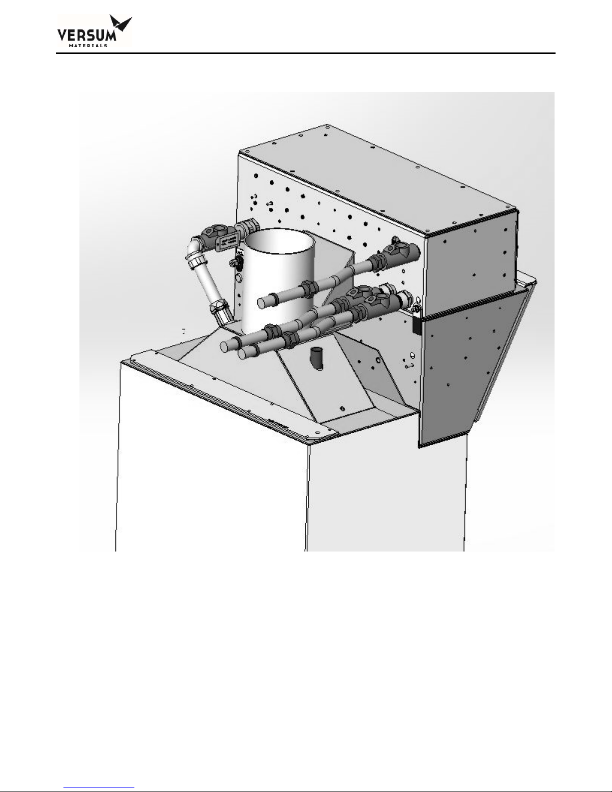
Chapter 2 - Installation
Figure 2-11: BSGS eV / BULKGUARD® eV Conduit and Conduit Seals (with eV ECC)
_______________________________________________________________________________________________________________
MNL000530 Revision 1 03/15/2018
BSGS eV / BULKGUARD eV
© Versum Materials, Inc. as of the revision and date shown. All rights reserved.
Page 2 - 24
Confidential and Proprietary Data
Page 71
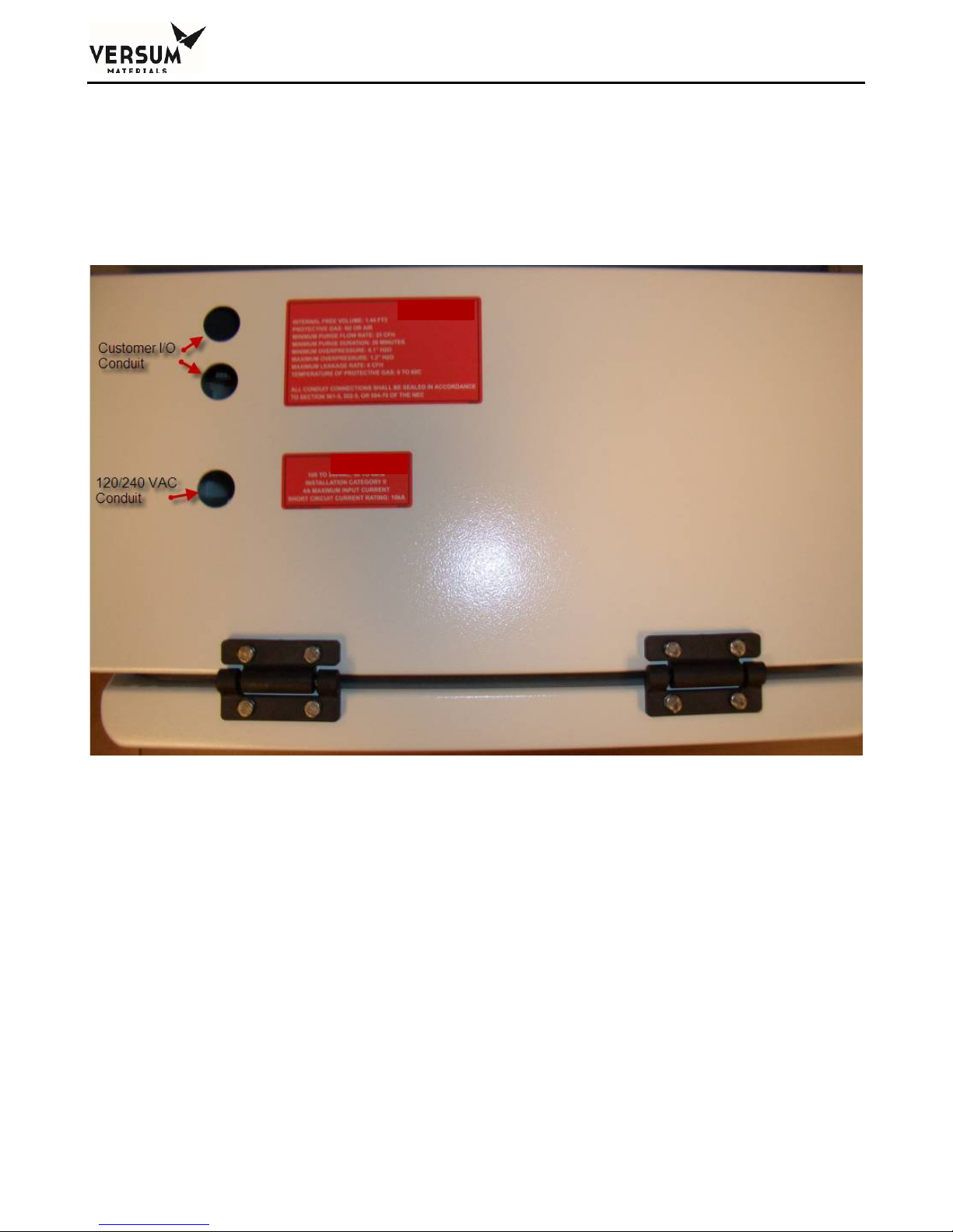
Chapter 2 - Installation
Systems which do not have the eV ECC installed with have conduit holes located on top of the AP11
controller. These holes would be covered up when the eV ECC is installed. A 1-1/8" (28.6 mm)
diameter hole for 3/4" conduit is supplied for connecting the 120/240 VAC power supply to the
system. Two additional holes are supplied for customer I/O and/or Ethernet Cable. Figure 2-12 and
Figure 2-13.
Figure 2-12: Top View of GASGUARD® AP11 Controller
_______________________________________________________________________________________________________________
MNL000530 Revision 1 03/15/2018
BSGS eV / BULKGUARD eV
© Versum Materials, Inc. as of the revision and date shown. All rights reserved.
Page 2 - 25
Confidential and Proprietary Data
Page 72
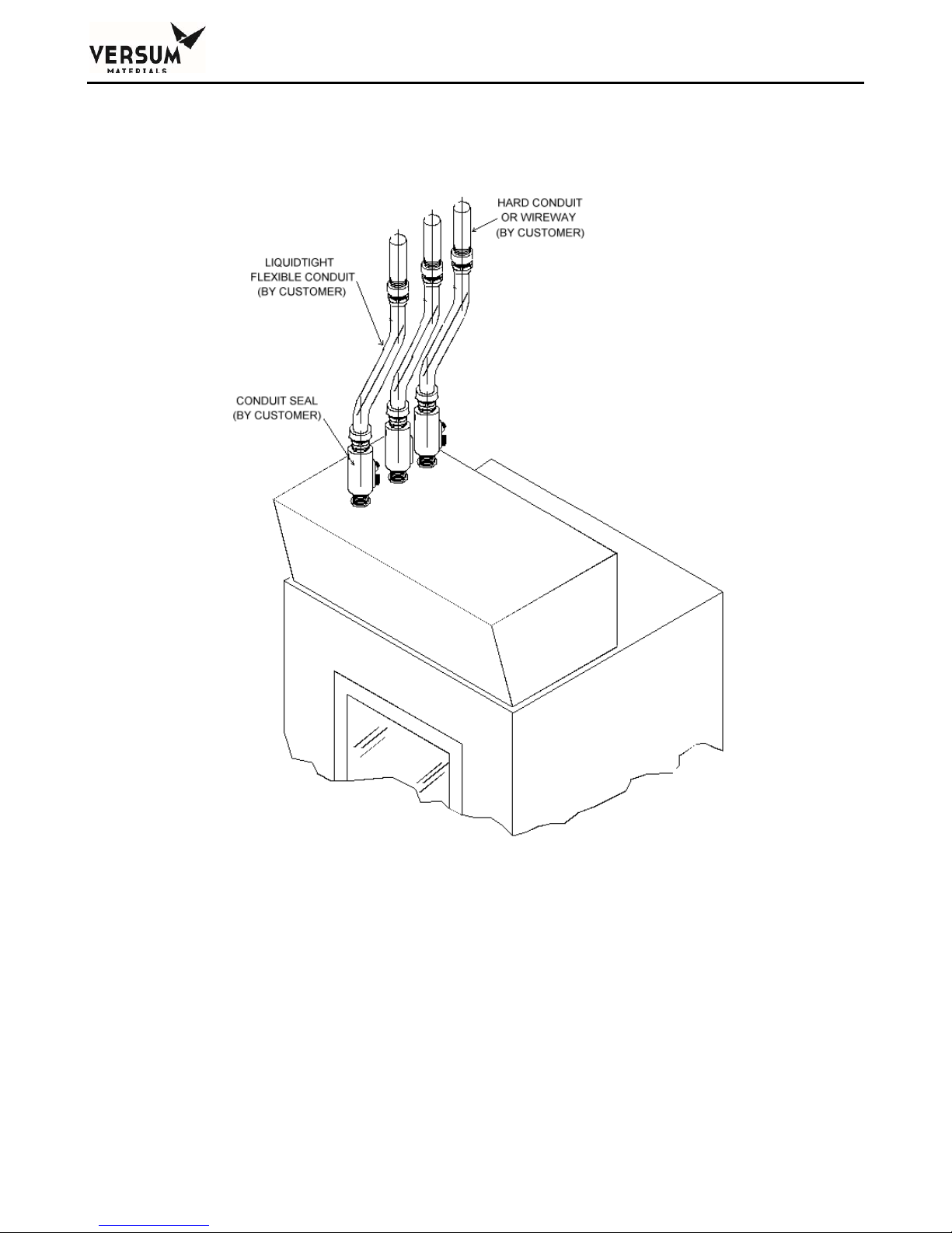
Chapter 2 - Installation
Figure 2-13: Conduit and Conduit Seals (no eV ECC installed)
_______________________________________________________________________________________________________________
MNL000530 Revision 1 03/15/2018
BSGS eV / BULKGUARD eV
© Versum Materials, Inc. as of the revision and date shown. All rights reserved.
Page 2 - 26
Confidential and Proprietary Data
Page 73
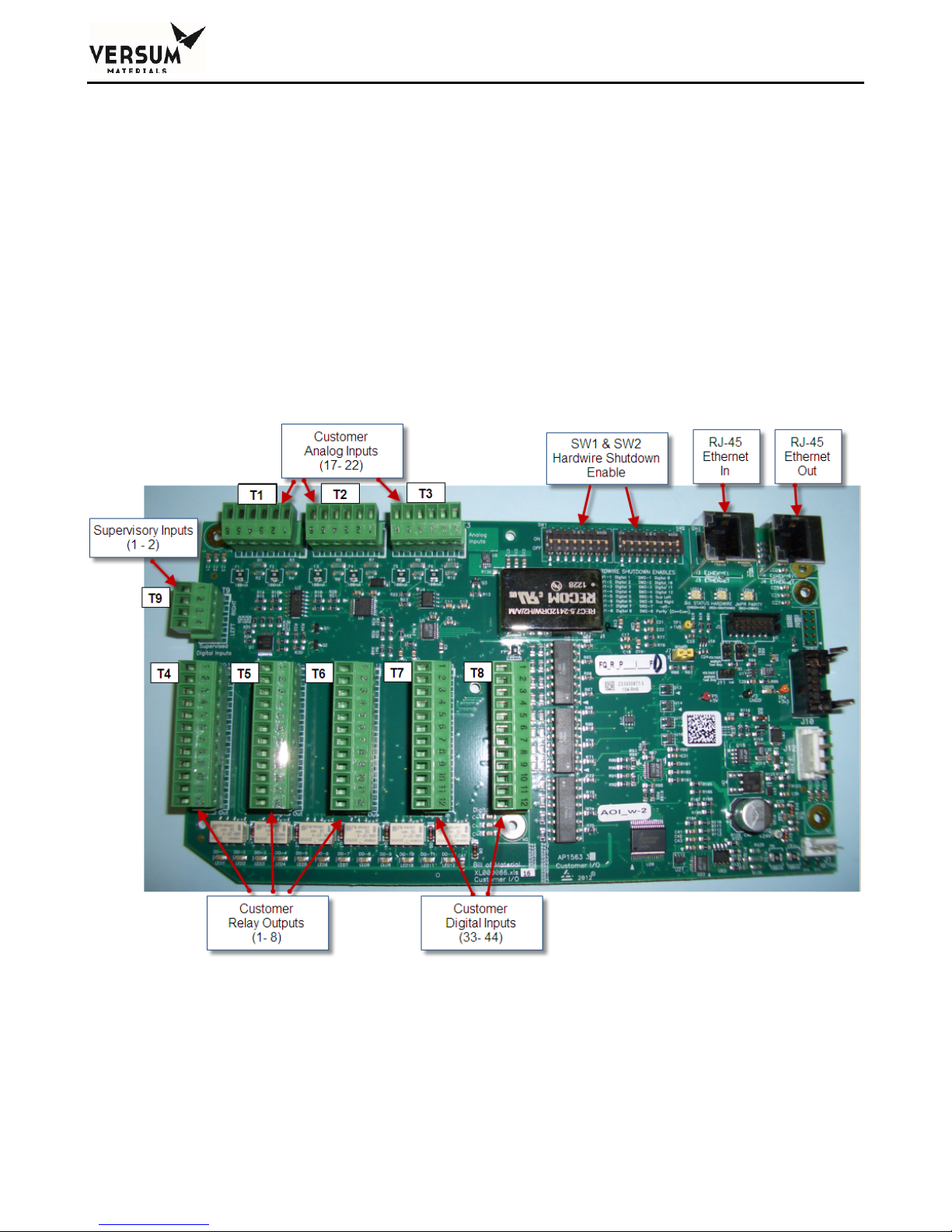
Chapter 2 - Installation
Field Signal Connections
In the AP11 BSGS eV / BULKGUARD eV module, all field I/O wiring connections are made to the
AP1563 customer I/O board located inside the left wall of the AP11 enclosure, and the AP1571 bulk
interface board located in the right bulk interface box located on the right side of the piping cabinet.
There are three types of I/O identified for the field connections: discrete (digital) inputs, discrete
(digital) outputs, and analog inputs. All the field and customer I/O signal connections to the AP11
Controller have been pre-assigned a specific location, although not all I/O connections or functions are
required on all systems. Figure 2-14 and Figure 2-15 show the general locations of these connections.
Details of these terminal blocks and termination points are shown in the electrical installation drawing,
Appendix A of this manual.
Figure 2-14: AP1563 Customer I/O Terminal Blocks
_______________________________________________________________________________________________________________
MNL000530 Revision 1 03/15/2018
BSGS eV / BULKGUARD eV
© Versum Materials, Inc. as of the revision and date shown. All rights reserved.
Page 2 - 27
Confidential and Proprietary Data
Page 74
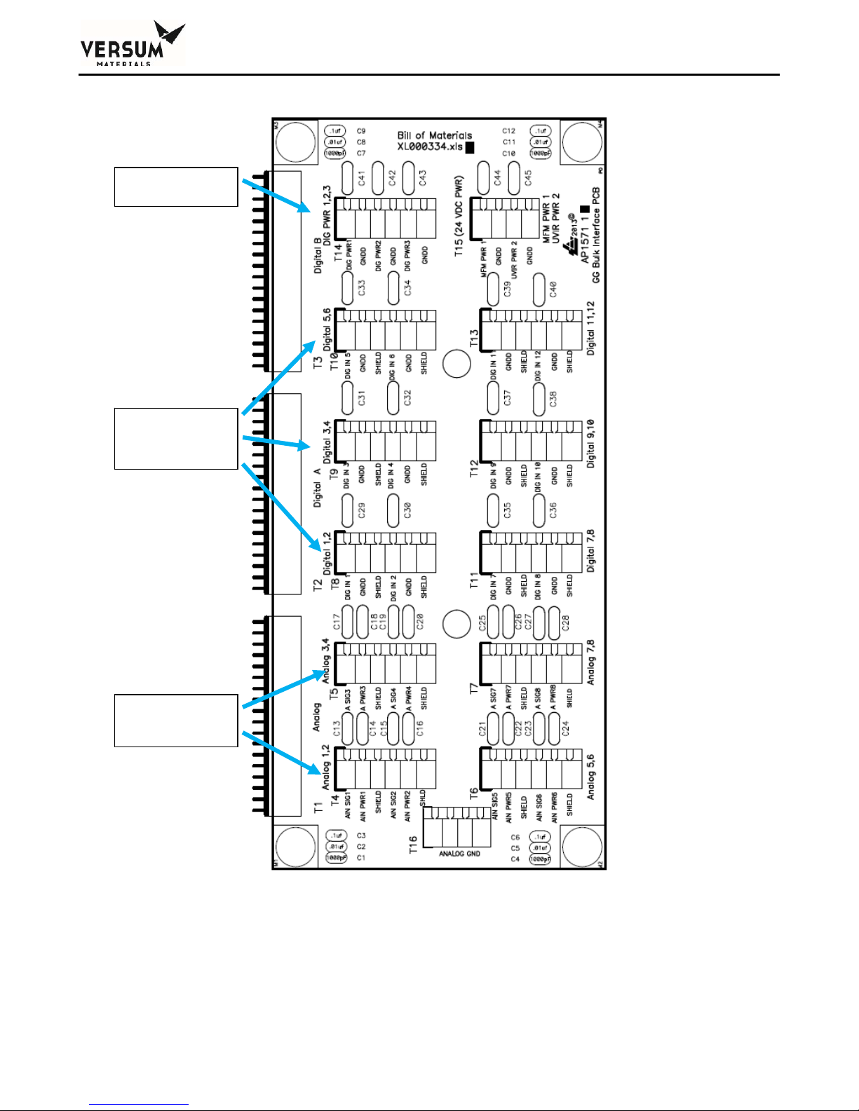
Chapter 2 - Installation
Power(5total)
DigitalInputs
(12total)
AnalogInputs
(8total)
Figure 2-15: Terminal block layout of I/O interface box
_______________________________________________________________________________________________________________
MNL000530 Revision 1 03/15/2018
BSGS eV / BULKGUARD eV
© Versum Materials, Inc. as of the revision and date shown. All rights reserved.
Page 2 - 28
Confidential and Proprietary Data
Page 75

Chapter 2 - Installation
CGA G-13 code, specifically section 12.2.1.5, states that an activation of the deluge sprinkler system
should result in a shutdown of the silane (SiH4) source. The customer should include this signal as part
of the Life Safety System input to the module, shown on the electrical installation drawing, Appendix
A of this manual.
Supervised Inputs
The system supports two supervised inputs from the customer interface. Supervised inputs are digital
inputs, which are monitored via a window comparator. These inputs are monitored for normal
operation, alarm type, and fault conditions.
A normally open switch is to be used as an input device. This switch must have a 10 kilo-ohm resistor
in parallel with the contacts. When the switch contacts are open the circuit will provide a signal, which
represents a normal operating condition. When the switch contacts are closed, the circuit will provide
a signal which indicates an alarm condition. An open wire in this circuit, or a short circuit, will
produce an out of range signal, which indicates a circuit fault.
Switch contacts must be rated for 20ma @ 24VDC. Switch contacts must be dry contact and external
wiring should not have any form of power applied to them.
Typically, supervised inputs are used with the life safety system. Figure 2-16 shows the supervisor
input wiring for use with the life safety system.
_______________________________________________________________________________________________________________
MNL000530 Revision 1 03/15/2018
BSGS eV / BULKGUARD eV
© Versum Materials, Inc. as of the revision and date shown. All rights reserved.
Page 2 - 29
Confidential and Proprietary Data
Page 76
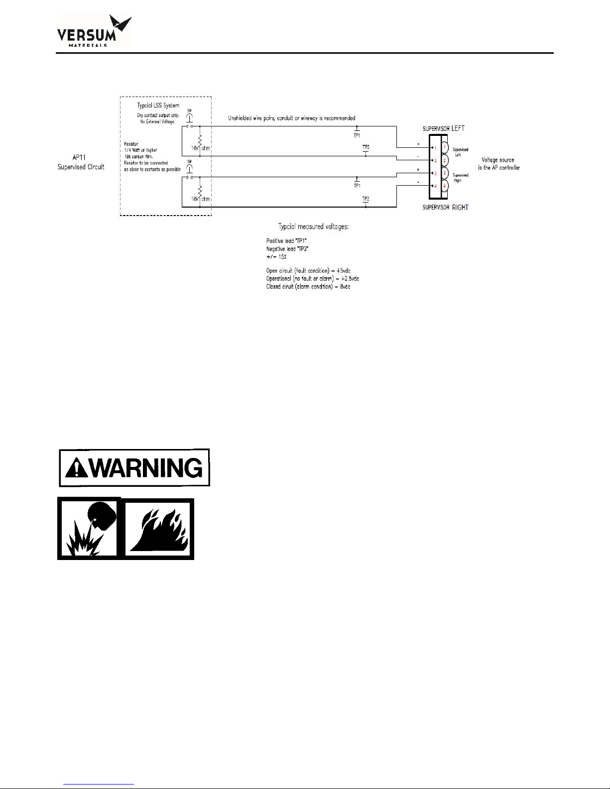
Chapter 2 - Installation
Figure 2-16: Supervisory Input Wiring
Available External I/O Communications
The BSGS eV / BULKGUARD® eV System is equipped
with a "vent unavailable" feature which prevents
process gas from being vented from the panel if the
scrubber system is not operating. Use of this feature
requires the installation of a hardwire between the
controller and the scrubber. Failure to utilize this
feature may result in the discharge of process gas to a
non-functioning vent system.
For a list of alarms and shutdowns specific to your system, see the Alarm Matrix included in the
drawings section of the operational manual.
_______________________________________________________________________________________________________________
MNL000530 Revision 1 03/15/2018
BSGS eV / BULKGUARD eV
© Versum Materials, Inc. as of the revision and date shown. All rights reserved.
Page 2 - 30
Confidential and Proprietary Data
Page 77

Chapter 2 - Installation
Digital Outputs Dry - Customer I/O board AP1563
24 VDC @ 1 Amp maximum
Relay Output #
1 T4-1 T4-2 T4-3
2 T4-4 T4-5 T4-6
3 T4-7 T4-8 T4-9
4 T4-10 T4-11 T4-12
5 T5-1 T5-2 T5-3
6 T5-4 T5-5 T5-6
7 T5-7 T5-8 T5-9
8 T5-10 T5-11 T5-12
9 T6-1 T6-2 T6-3
NO
Customer Brd
COMMON
NC
10 Factory use only Factory use only Factory use only
11 Factory use only Factory use only Factory use only
12 T6-10 T6-11 T6-12
_______________________________________________________________________________________________________________
MNL000530 Revision 1 03/15/2018
BSGS eV / BULKGUARD eV
© Versum Materials, Inc. as of the revision and date shown. All rights reserved.
Page 2 - 31
Confidential and Proprietary Data
Page 78
Chapter 2 - Installation
Digital Inputs (Customer)
(Customer I/O board AP1563)
Digital Input #
Customer Brd
Signal
Customer Brd
Return
Hardwire Switch
5 / 6* T9-LEFT (+) T9-LEFT (-) SW2-5
7 / 8* T9-RIGHT (+) T9-RIGHT (-) SW2-6
33* T7-1 T7-2 SW1-1
34* T7-3 T7-4 SW1-2
35* T7-5 T7-6 SW1-3
36* T7-7 T7-8 SW1-4
37* T7-9 T7-10 SW1-5
38* T7-11 T7-12 SW1-6
39* T8-1 T8-2 SW1-7
40* T8-3 T8-4 SW1-8
Position
41* T8-5 T8-6 SW2-1
42* T8-7 T8-8 SW2-2
43* T8-9 T8-10 SW2-3
44* T8-11 T8-12 SW2-4
* Each digital-input can be individually configured to provide a hardwire shutdown alarm function.
Figure 2.6 shows the location of SW1 & SW2 hardwire switches.
To configure an input as a hardwire, the corresponding switch shown in the above table must be set to
the ON position.
_______________________________________________________________________________________________________________
MNL000530 Revision 1 03/15/2018
BSGS eV / BULKGUARD eV
© Versum Materials, Inc. as of the revision and date shown. All rights reserved.
Page 2 - 32
Confidential and Proprietary Data
Page 79

Chapter 2 - Installation
SW2-8 Parity Switch setting:
- "On" if total number of active hardwire circuits is 0, 2, 4, 6, 8, 10, or 12.
- "Off" if total number of active hardwire circuits is 1, 3, 5, 7, 9, or 11.
Customer Board parity LED will be green when switches are configured correctly.
A digital-input that is in the OPEN state and configured as a hardwire will have the same functional
effect as pressing the EMO (Emergency Stop) switch.
Analog Inputs (Customer)
(AP1563 Customer I/O board)
Analog inputs supplied power at 24VDC fused @ 100 mA each w/ 100 Ω series resistor.
Analog Input #
Customer Brd
Signal
Customer Brd
24 VDC+
Customer Brd
GND
17 T1 - 5 T1 - 6 T1 - 4
18 T1 - 2 T1 - 3 T1 - 1
19 T2 - 5 T2 - 6 T2 - 4
20 T2 - 2 T2 - 3 T2 - 1
21 T3 - 5 T3 - 6 T3 - 4
22 T3 - 2 T3 - 3 T3 - 1
_______________________________________________________________________________________________________________
MNL000530 Revision 1 03/15/2018
BSGS eV / BULKGUARD eV
© Versum Materials, Inc. as of the revision and date shown. All rights reserved.
Page 2 - 33
Confidential and Proprietary Data
Page 80

Chapter 2 - Installation
User Power (Customer)
(AP1563 Customer I/O board)
The AP11 customer board supports six Analog-Input (AI) channels, each of which can be
independently configured for 0-5V or 4-20mA inputs. Three user-connections (per channel) are
provided: +24V-power, +24V-gnd, and signal. A common isolated power-supply is used for all
channels, however each channel’s power is individually fused/current-limited. The combined powersupply loading of all channels must be less than 200mA. In some configurations, it may be possible to
exceed this limit. It is the user’s responsibility to ensure this constraint is not violated. The following
sections provide detailed guidelines on how to connect and use the customer board.
There are 3 types of devices as shown in Figure 2-17 below. (AP11 connections are shown on the left)
+24
+24
Signal
+
Externalpower
Signal
Signal
Gnd
Gnd
(noAP11connection)
‐
2‐Wire
3‐Wire
Externally‐Powered
Figure 2-17
2-Wire (4-20mA) Device: Device has 2 wires: power and signal. The device draws up to 20 mA.
3-Wire Device (Powered from AP11): Device has 3 wires: power, signal, and ground. The current
draw should be included on the manufacturer’s data sheet and should be plugged into the table below.
Externally-Powered: These devices receive power for their operation from another source and
interface with the AP11 using 2 wires: signal and ground.
There are two calculations that must be performed when connecting Analog devices to an AP11.
1. The total current-consumption calculation of AP11-powered devices
2. The cable-resistance calculation for each device connection
The following sections provide detailed examples on how to perform these calculations.
_______________________________________________________________________________________________________________
MNL000530 Revision 1 03/15/2018
BSGS eV / BULKGUARD eV
© Versum Materials, Inc. as of the revision and date shown. All rights reserved.
Page 2 - 34
Confidential and Proprietary Data
Page 81
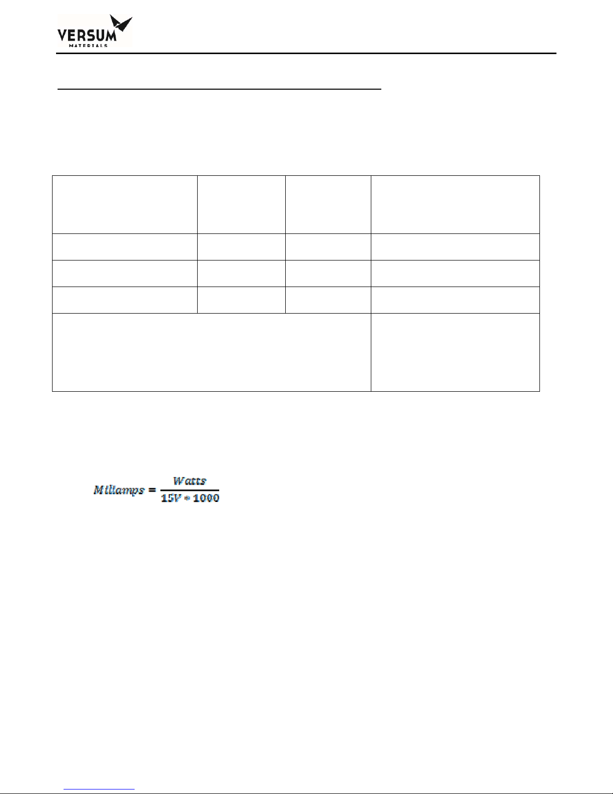
Chapter 2 - Installation
Current-Consumption Calculations for AP11-powered devices:
The current-consumption calculation is necessary to ensure the total draw of all connected devices is
less than the 200mA capacity of the Customer Board. If using all 2-wire devices, no calculation is
required as the AP11’s capacity is sufficient for this configuration. For all other cases, use the
following table to determine the current-consumption.
Type
Number of
Devices
Multiply by
current draw
per device
Total
2-Wire (4-20mA) Device X 20 mA = mA
3-Wire Device X mA = mA
Externally-Powered Device X 0 mA = 0 mA
TOTAL
(Sum of Above)
mA
Can NOT exceed 200 mA
Note: If the manufacturer specifies power consumption in watts instead of current in
milliamps, assume that the device is receiving 15V and approximate the current draw as
follows:
_______________________________________________________________________________________________________________
MNL000530 Revision 1 03/15/2018
BSGS eV / BULKGUARD eV
© Versum Materials, Inc. as of the revision and date shown. All rights reserved.
Page 2 - 35
Confidential and Proprietary Data
Page 82
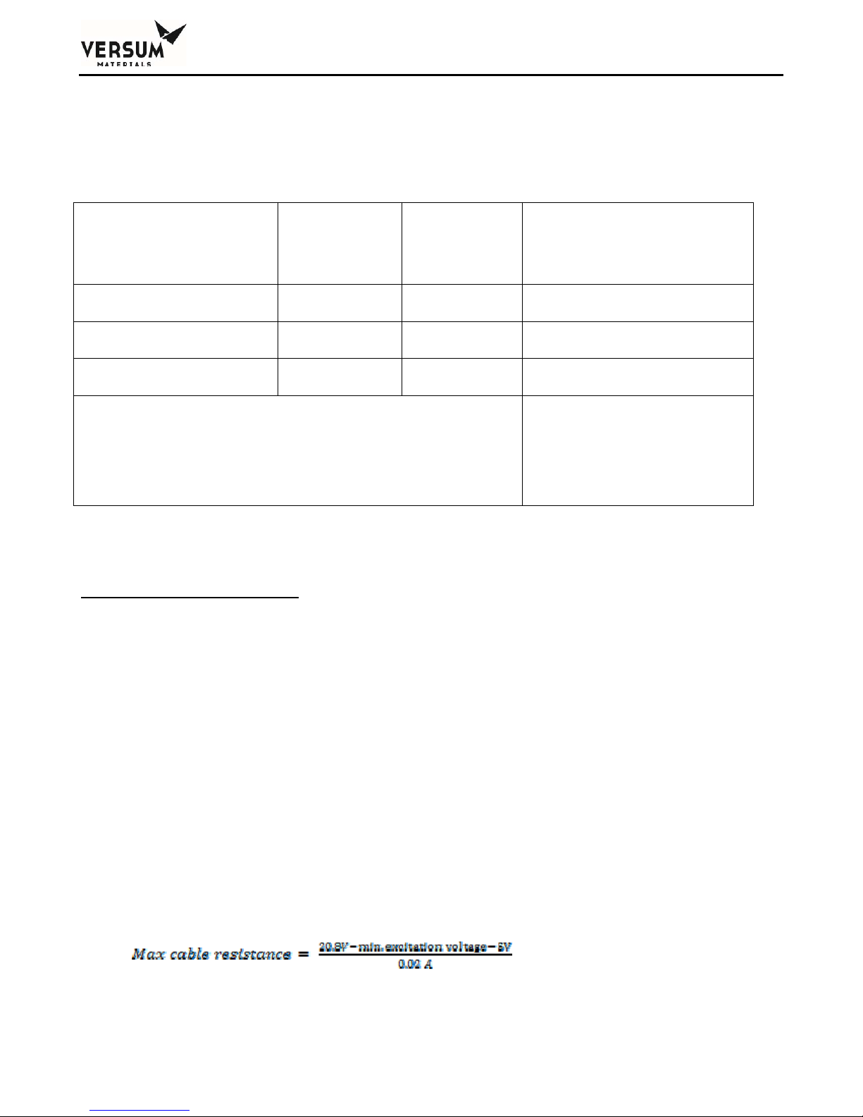
Chapter 2 - Installation
EXAMPLE:
An AP11 needs to connect to three 2-wire devices and two 3-wire devices and one externally-powered
device. The manufacturer of the 3-wire device specifies that it will draw no more than 50 mA.
Type
Number of
Devices
Multiply by
current draw
per device
Total
2-Wire (4-20mA) Device 3 X 20 mA = 60 mA
3-Wire Device 2 X 50 mA = 100 mA
Externally-Powered Device 1 X 0 mA = 0 mA
TOTAL
(Sum of Above)
160 mA
Can NOT exceed 200 mA
In this example, the calculated current draw (160mA) is below the AP11’s capacity (200mA) so the
configuration is valid.
Cable-Resistance Calculation:
Resistance in the cables used to connect field-devices to an AP11 results in voltage-drops that must be
considered. These voltage-drops directly subtract from the power-supply’s output used to power a
device. The resultant voltage (as seen by the device) must be sufficient to satisfy the minimum
excitation voltage specification for a given device to operate properly. This specification is available
from the manufacturer of the device.
To satisfy a devices excitation spec, the “actual” cable-resistance must be less than the “maximum”
cable-resistance that can be supported. Example calculations are shown below. It should be noted that
calculations differ for each of the device types.
2-Wire (4-20mA) Device: Device has 2 wires: power and signal. The device draws up to 20 mA.
The maximum cable resistance is equal to the minimum voltage seen at the power pin on the AP11
minus the minimum excitation voltage of the device (as provided by manufacturer) minus the voltage
caused by the input resistance of the AP11 all divided by the maximum current of the device.
_______________________________________________________________________________________________________________
MNL000530 Revision 1 03/15/2018
BSGS eV / BULKGUARD eV
© Versum Materials, Inc. as of the revision and date shown. All rights reserved.
Page 2 - 36
Confidential and Proprietary Data
Page 83
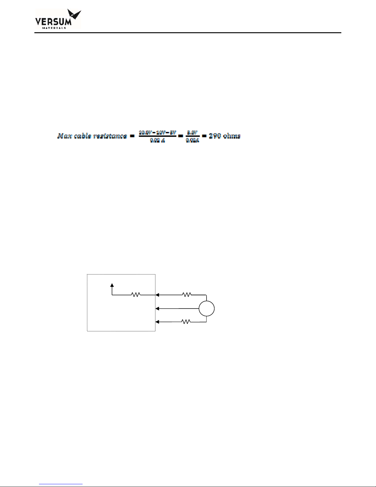
Chapter 2 - Installation
Cable resistance is calculated as the resistance per meter times the number of meters that the signal
travels. IMPORTANT: Both the wire going to and returning from the sensor must be included.
Cable resistance = Ohms per meter * meters of cable * 2 (this is for wire to and from sensor)
EXAMPLE:
A sensor with an excitation spec of 10v is at the end of a 100 meter 22/2 cable. The
manufacturer specifies that the 22 AWG wire has a resistance of 0.0527 ohms/meter.
Cable resistance = 0.0527 ohms/meter * 100 meters * 2
(actual) = 10.54 ohms
The calculations confirm that the “actual” cable resistance (10.54 ohms) is less than the Max cable
resistance (290 ohms) so the excitation specification is satisfied.
3-Wire Device (Powered from AP11): Device has 3 wires: power, signal, and ground.
The current draw and minimum operating voltage of the device should be included on the
manufacturer’s data sheet. The voltage seen by the device is reduced by the resistance of the cable
going to the device and by a 100-ohm resistor within the AP11. Calculations to determine the
maximum cable resistance are shown in Figure 2-18 below:
AP11
Excitation Voltage (V
+22.8V
): Minimum operating voltage of the device as specified by the manufacturer
E
100Ω
Gnd
Signal(20mA)
Figure2‐18
R
R
wire
wire
Current Draw (IL): The amount of current the sensor draws as specified by the manufacturer. This is
measured in Amps.
Note: If the manufacturer specifies power consumption in watts instead of current in
milliamps, assume that the device is receiving it’s minimum voltage and approximate the
current draw as follows:
_______________________________________________________________________________________________________________
MNL000530 Revision 1 03/15/2018
BSGS eV / BULKGUARD eV
© Versum Materials, Inc. as of the revision and date shown. All rights reserved.
Page 2 - 37
Confidential and Proprietary Data
Page 84
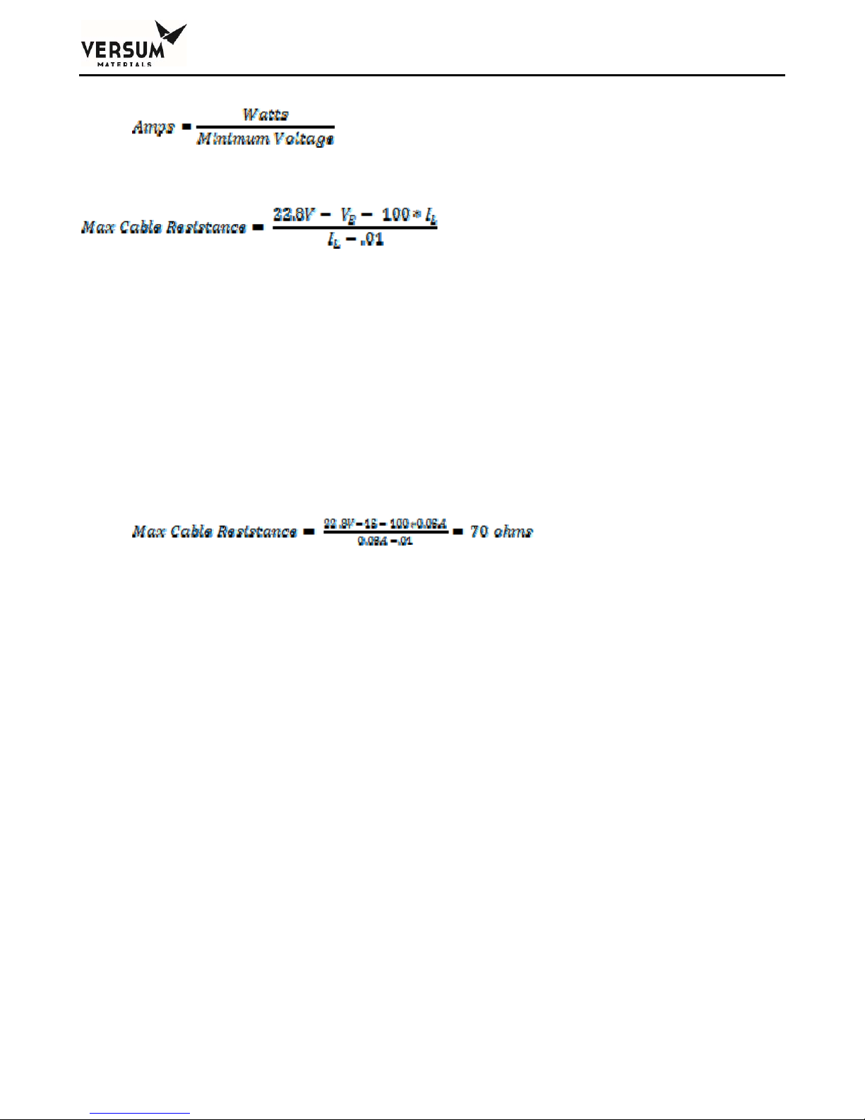
Chapter 2 - Installation
Max Cable Resistance: The maximum resistance of the wiring to and from the sensor.
Cable resistance is calculated as the resistance per meter times the number of meters that the signal
travels. IMPORTANT: Both the wire going to and returning from the sensor must be included.
Cable resistance = Ohms per meter * meters of cable * 2 (this is for wire to and from sensor)
EXAMPLE:
A sensor that draws 50 mA and has a minimum excitation voltage of 15V is at the end of 100
meters of 22/3 cable. The manufacturer specifies that the 22 AWG wire has a resistance of
0.0527 ohms/meter.
Cable resistance = 0.0527 ohms/meter * 100 meters * 2
(actual) = 10.54 ohms
The calculations confirm that the “actual” wire resistance (10.54 ohms) is less than the max
wire resistance (70 ohms) so the excitation specification is satisfied.
_______________________________________________________________________________________________________________
MNL000530 Revision 1 03/15/2018
BSGS eV / BULKGUARD eV
© Versum Materials, Inc. as of the revision and date shown. All rights reserved.
Page 2 - 38
Confidential and Proprietary Data
Page 85
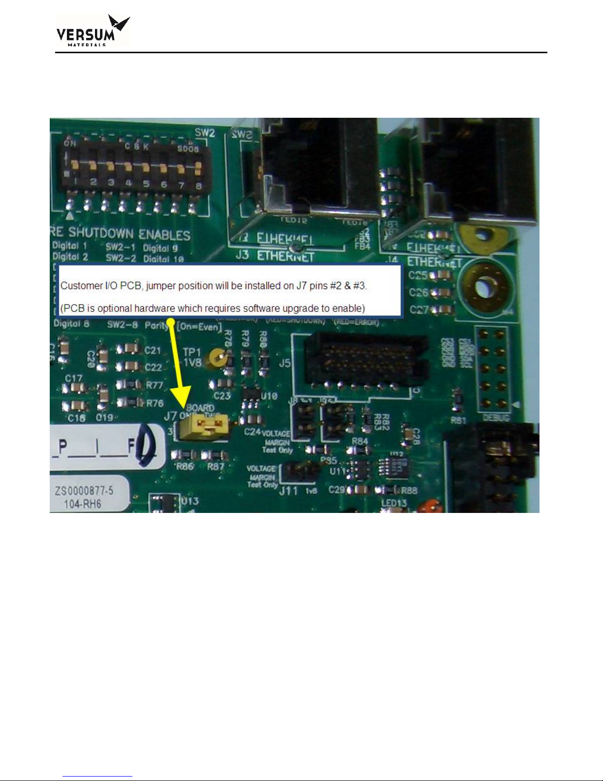
Chapter 2 - Installation
On BSGS eV / BULKGUARD eV modules, jumper J7 is factory set as shown in Figure 2-19 for the
Customer I/O board.
Figure 2-19: GASGUARD® AP11 Customer board "J7" jumper configuration.
_______________________________________________________________________________________________________________
MNL000530 Revision 1 03/15/2018
BSGS eV / BULKGUARD eV
© Versum Materials, Inc. as of the revision and date shown. All rights reserved.
Page 2 - 39
Confidential and Proprietary Data
Page 86
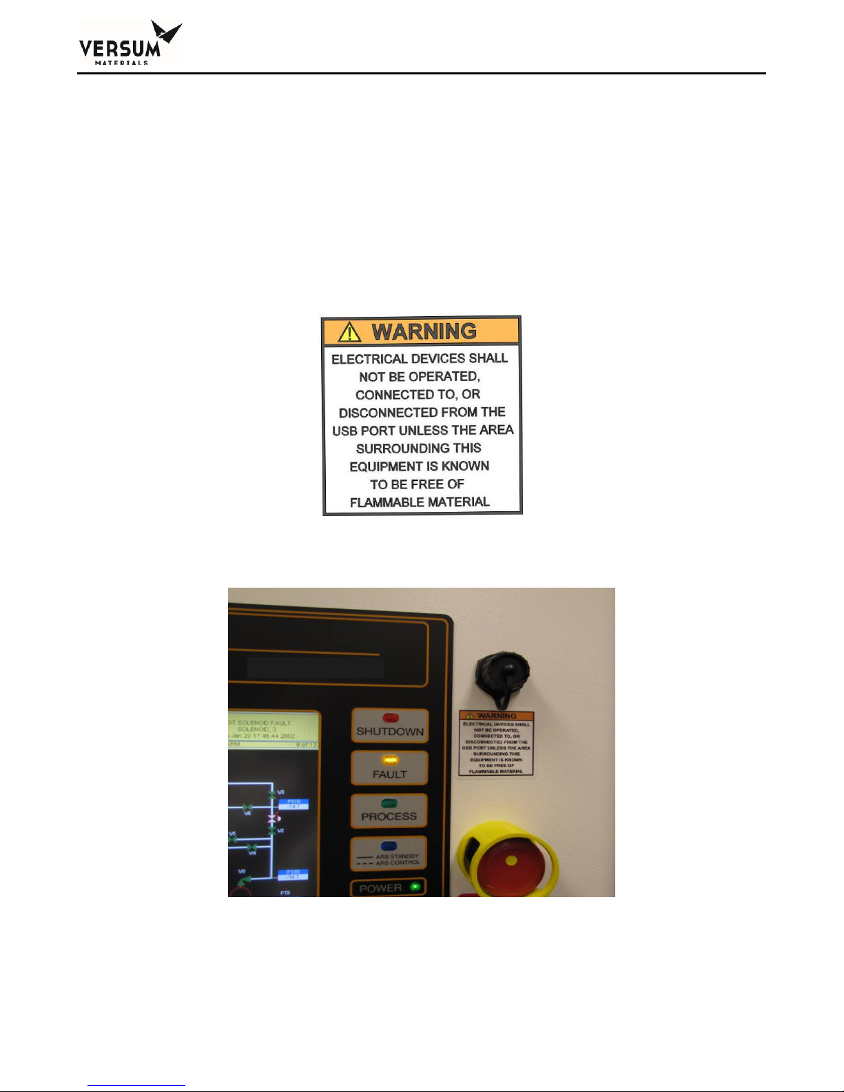
Chapter 2 - Installation
USB Connection Port
The AP11 controller USB port is located on the face of the controller. The USB port allows a USB
connection to be made without having to open the controller door. Electrical devices should never be
operated, connected to, or disconnected from the USB port unless the area surrounding the equipment
is known to be free of flammable material. The USB port on the face of the controller will also have a
warning label (Figure 2-20) for operation in a flammable area.
Each USB connector type is 2.0 format. 4ea USB ports available inside the controller, with one of the
ports extended externally to the AP11 controller door as shown in Figure 2-21
Figure 2-20: USB Port Warning Label
Figure 2-21: AP11 Controller USB Port on the Face of the Controller
_______________________________________________________________________________________________________________
MNL000530 Revision 1 03/15/2018
Page 2 - 40
BSGS eV / BULKGUARD eV
© Versum Materials, Inc. as of the revision and date shown. All rights reserved.
Confidential and Proprietary Data
Page 87

Chapter 2 - Installation
The USB parameters for the port that is extended to the door of the AP11 controller, are listed below.
Voltage: 5V +/- 10%
Current: 2A maximum
Capacitance: 100.01uF +/- 20%
Pneumatic Connections
The AP11 controller requires a pneumatic supply for Z-purge and pneumatic valve operation. A
pneumatic supply of inert gas without oxygen, such as nitrogen, is recommended. It is strongly
advised to not use clean dry air for pneumatic supply unless there is a high degree of confidence
that it will maintain purity as per ISO 8573-1 Class 2. Moisture in clean dry air will promote
corrosion of electrical components and reduce controller performance and reliability.
The pneumatic supply must be regulated to 85-95 psig (5.9-6.6 barg). Maximum allowable working
pressure is 100 psig (6.9 barg). Over-pressurization protection, such as a safety relief valve, must be
provided to protect the internal solenoids. The flow rate required for pneumatic valve operation is 2
CFH (1 LPM). A 1/4" compression fitting at the back of the controller is provided for the pneumatic
supply inlet connection as shown in Figure 2-22. Piping for the pneumatic supply must be protected
from mechanical damage.
This supply is also used for Type Z purge of the electrical enclosure. Z-purge is enabled on all BSGS
eV / BULKGUARD eV module controllers because a clean, dry nitrogen purge will promote controller
longevity and guard against water intrusion when installed outdoors. In certain areas, the Type Z
purge is required to maintain a positive pressure at or above 0.1" water column (24.9 Pa). This is in
accordance with Article 496 of the National Fire Protection Agency (NFPA) regulations. In
applications where Type Z purge is required, the controller will be equipped with a pressure switch to
monitor the pressure. The Type Z purge will require a purging flow rate of 7 lpm/15 CFH for 30
minutes before applying power to the controller, each time any of the three electrical enclosure doors
are opened. Do not exceed 7 lpm (15 CFH) during purge of the BSGS eV / BULKGUARD eV.
_______________________________________________________________________________________________________________
MNL000530 Revision 1 03/15/2018
BSGS eV / BULKGUARD eV
© Versum Materials, Inc. as of the revision and date shown. All rights reserved.
Page 2 - 41
Confidential and Proprietary Data
Page 88
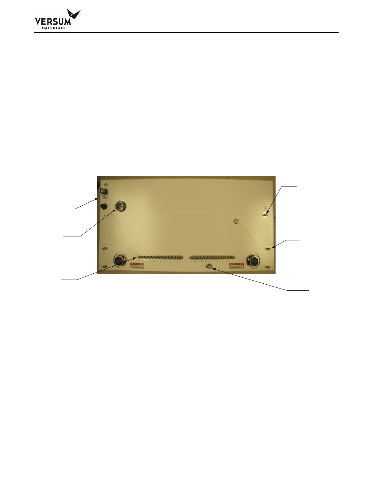
Z-Purge Procedure
The Z purge pressure is controlled by a needle valve at rear of controller. After opening the controller
in a suspected hazardous area it is necessary to use the following procedure to re-establish the Z-purge
before operating the controller:
1. Close the controller front and tighten both latches completely.
2. Open the needle valve 4 to 5 turns (counter-clockwise). Allow the controller to purge for 30
minutes.
3. Adjust needle valve to satisfy the “Z-Purge” alarm (approximately 2 total turns open).
Flow requirements to operate the solenoid valves are very small, less than 1 LPM (2 CFH). If Type Z
purge is required, a flow rate of 7 LPM (15 CFH) will be needed, depending on the tightness of the
individual controller and the installation. BSGS eV / BULKGUARD eV will require 7 LPM (15CFH).
Flowrates should be monitored during Type Z purge. Do not exceed 7 LPM (15 CFH) during purge of
BSGS eV / BULKGUARD eV.
Instrument N2
connection ¼”
compression
fitting
Chapter 2 - Installation
Ground Lug
Alarm Horn
Pneumatic
Connections
(typical)
Source Container Pneumatic Connections
Depending on the BSGS eV / BULKGUARD eV module configuration, the AP11 controller may be
configured to supply a single pneumatic signal to the source A1/A2 and B1/B2 container valve, or
multiple pneumatic signals to source A container valves and perform tube switching.
If the module was configured with a pneumatic signal for the source container, a single pneumatic tube
or tube bundle will be supplied by Versum Materials, Inc. A single pneumatic tube is typically
supplied for Y containers, drums, and NH3 ISO containers. A pneumatic tube bundle is typically
supplied for tube trailers and multi-tube ISO containers. Installation details can be found in the
mechanical installation drawings located in Appendix A of this manual.
Figure 2-22. Rear View of GASGUARD® AP11 Controller
Mounting
Stud (4)
Z-Purge
Valve
_______________________________________________________________________________________________________________
MNL000530 Revision 1 03/15/2018
BSGS eV / BULKGUARD eV
© Versum Materials, Inc. as of the revision and date shown. All rights reserved.
Page 2 - 42
Confidential and Proprietary Data
Page 89
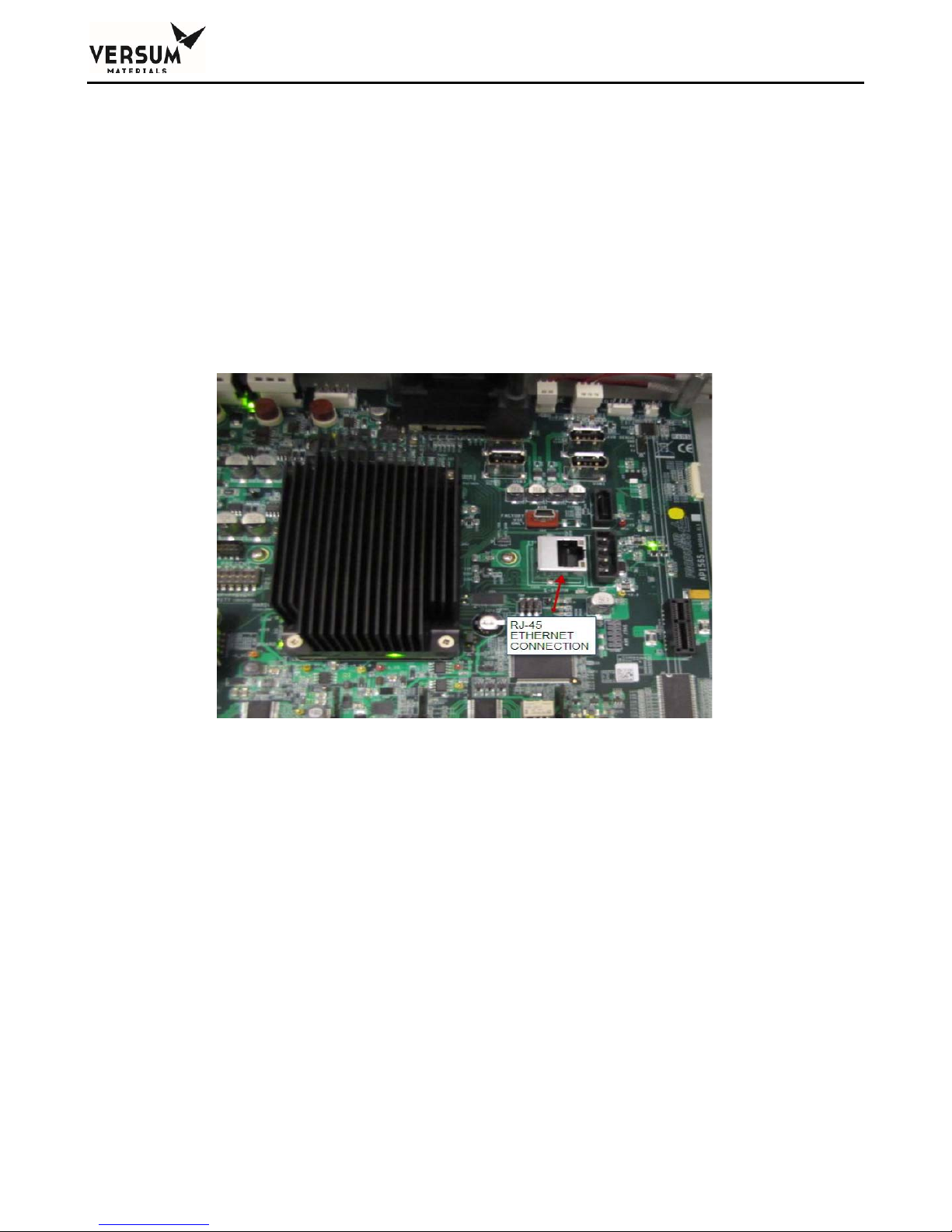
Chapter 2 - Installation
GASGUARD® Networking
General Description
Remote monitoring of GASGUARD® systems such as the BSGS eV / BULKGUARD® eV can be
attained using the GASGUARD
GCS (Global Communications System). Either method can provide continuous on-line 24 hour per
day monitoring of the status of all connected GASGUARD® Cabinets, VMBs and BSGS systems. The
GASGUARD® AP11 communicates to GCS or OPC via Ethernet. Figure 2-23 shows the location of
the Ethernet connection on the AP11 carrier board.
®
OPC Server software or Versum Materials, Inc.’s SCADA system;
Figure 2-23: AP11 carrier board Ethernet connection
GCS Ethernet Network Wiring Configuration
A GCS is typically integrated into the site’s Ethernet network. Figure 2-24 depicts the typical network
architecture of a GCS. In most instances, the GCS is connected to two separate networks. One subnet
will interconnect only the gas controller equipment, while the other subnet will be the connectivity to
the overall site Local Area Network. Using this architecture, the gas controller network traffic will not
be adversely affected by other nodes on the site LAN; furthermore, if the site needs to disconnect the
GCS from their network -- for instance when a remote support person accesses the system – the ability
to monitor the gas controller network will not be affected. The connection to the site LAN allows for
connectivity from office PC’s to the GCS for Global View sessions as well as ODBC data downloads.
The GCS may also be equipped with additional options which will require its connectivity to
additional LAN’s. Such will be the case if the GCS will need to supply gas availability data to a site’s
tool annunciation system. GCS uses standard TCP/IP network protocol to communicate over all
networks.
_______________________________________________________________________________________________________________
MNL000530 Revision 1 03/15/2018
BSGS eV / BULKGUARD eV
© Versum Materials, Inc. as of the revision and date shown. All rights reserved.
Page 2 - 43
Confidential and Proprietary Data
Page 90
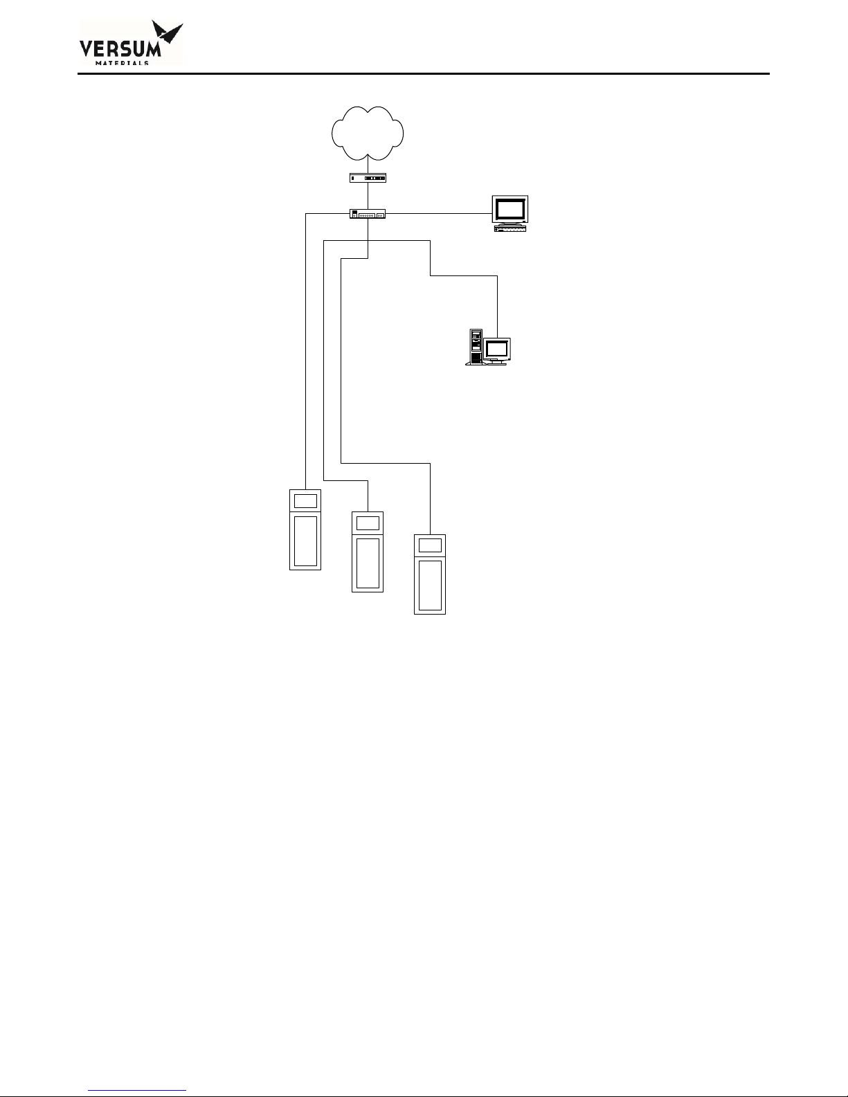
Chapter 2 - Installation
Customer's Entire
Network
10/100 BASE-T Subnet
Gateway, Router and/or
Bridge
10/100 BASE-T Switch/
Hub
10/100 BASE-T Ethernet
Network (Star Topology)
Gasguard AP Ethernet Network OPC Server
Other Networked Customer
Computers or Equipment
Residing on this Network Subnet
HMI or SCADA Computer
Windows NT or Windows 2000
Gasguard AP Controller
(Ethernet)
Gasguard AP Controller
(Ethernet)
Gasguard AP Controller
(Ethernet)
Figure 2-24 Typical GCS Network Architecture
_______________________________________________________________________________________________________________
MNL000530 Revision 1 03/15/2018
BSGS eV / BULKGUARD eV
© Versum Materials, Inc. as of the revision and date shown. All rights reserved.
Page 2 - 44
Confidential and Proprietary Data
Page 91

Chapter 2 - Installation
Installation and Pre-Facilitation Checklist
A GASGUARD® BSGS eV / BULKGUARD® eV Installation and Pre-Facilitation Checklist is
provided in an appendix of this manual. This checklist will assist the owner/installer with items to be
completed prior to startup. The Installation and Pre-Facilitation Checklist is included in Appendix D
of this manual.
Startup and Commissioning Checklist
A GASGUARD® BSGS eV / BULKGUARD® eV Startup and Commissioning Checklist is provided in
an appendix of this manual. This checklist is used to verify that the system is connected properly and
is ready for the Operational Readiness Inspection, commissioning, and start up. The Startup and
Commissioning Checklist is included in Appendix E of this manual.
Operational Readiness Inspection
Before a BSGS eV / BULKGUARD eV module or system can be started up, an Operational Readiness
Inspection (ORI) must be completed. The ORI is a checklist that assures equipment placement,
connection to all required utilities, verification of operability, startup and eventual commissioning prior
to the introduction of process gas into the module or system. The ORI checklist is included in
Appendix F of this manual.
OSHA Process Safety Management (PSM)
The United States Government, through OSHA, has established threshold quantities of hazardous
gases. When exceeded, OSHA requires the system owner to establish a PSM program to inform
employees of the operational characteristics and hazards of system operation. Contact OSHA, or ask
your Versum Materials, Inc. representative for information on PSM threshold quantities and if
establishing a PSM program applies to your facility.
_______________________________________________________________________________________________________________
MNL000530 Revision 1 03/15/2018
BSGS eV / BULKGUARD eV
© Versum Materials, Inc. as of the revision and date shown. All rights reserved.
Page 2 - 45
Confidential and Proprietary Data
Page 92

Chapter 2 - Installation
6.0 Explosive Atmosphere (ATEX) Installations
BSGS eV / BULKGUARD eV controllers that have the label shown in Figure 2-25 has been
certified to comply with European Union ATEX Directive 2014/34/EU of the European
Parliament and Council when properly installed in accordance with the guidelines and
instructions referenced in this section.
BSGS eV / BULKGUARD eV controllers with the following label attached for explosion protection
are of Group II, Category 3; intended for use only in areas where explosive atmospheres of gas are
unlikely to occur, or if they do occur are likely to do so infrequently or for a short period.
_______________________________________________________________________________________________________________
MNL000530 Revision 1 03/15/2018
BSGS eV / BULKGUARD eV
© Versum Materials, Inc. as of the revision and date shown. All rights reserved.
Page 2 - 46
Confidential and Proprietary Data
Page 93

Chapter 2 - Installation
6.1 Label Markings
The ATEX label placed on the AP11 controller includes the following information (symbols follow in
order starting at the upper left corner):
The CE Symbol which reflects conformity with the European Directives
The Hexagonal “Ex” Symbol for Explosive Atmosphere
The equipment group symbol for the electrical apparatus which is II. All industry gases are
classified as Group II gases.
The equipment category number 3. The equipment category number 3 means the equipment
is suitable for an environment where an explosive atmosphere is unlikely to occur, occurs
infrequently, or occurs for only a short period of time.
The atmosphere symbol “G”. “G” means that product is safe in an explosive GAS
atmosphere.
Symbol “Ex”. This symbol stands for the equipment has been tested under the latest
European Harmonized Standard for use in Explosive Atmospheres.
Symbol “ic” for intrinsic safety.
Symbol “pz” for pressurization. Pressurization prevents the ingress of an explosive
atmosphere to a space that may contain a source of ignition. This is used for the controller.
Symbol “IIC’ for the apparatus gas group.
The symbol indicating the maximum surface temperature, T4. T4 indicates that the
maximum surface temperature does not exceed 135°C.
The symbol “X” for special conditions of installation and relevant use for safety. The
normal ambient temperature range in the ATEX standard is considered to be -20°C to 60°C.
Since the temperature range for the AP11 varies from the normal range, an X is included on
the label markings.
The ambient temperature range, Ta.
_______________________________________________________________________________________________________________
MNL000530 Revision 1 03/15/2018
BSGS eV / BULKGUARD eV
© Versum Materials, Inc. as of the revision and date shown. All rights reserved.
Page 2 - 47
Confidential and Proprietary Data
Page 94

Chapter 2 - Installation
6.2 Special Conditions for Safe Use (X)
Environmental Limits
BSGS eV / BULKGUARD eV controllers are intended for indoor installation. They
have been evaluated for installation in locations providing adequate protection against
the entry of water.
AP11 controllers are intended for use in ambient temperatures in the range of -20C to
+60C and should not be used outside this range.
DO NOT rub the surface of the touch screen with a dry cloth. Electrostatic charge
generated by the friction may result. When cleaning the face with a damp cloth, take
the measures of an electrostatic discharge such as earth band, ionic shower, etc.
Installation Conditions
When installing the equipment, appropriate precautions must be taken to ensure that the
equipment has been connected to earth. Refer to Section 5 of this manual for more
information.
Installation of this equipment shall be carried out in accordance with the installation
Power Supply
Input power supply specs must not exceed the maximum values as listed in Section 5 of
Maintenance
Before opening the controller enclosure ensure that there is no danger of explosion in
Before turning the power supply ON, be sure to close the enclosure cover tightly and
Only qualified Versum Materials personnel should service the controller. Substitution
standards for potentially explosive atmospheres. Installation, startup and maintenance
must be carried out only by personnel trained in explosion protection.
this manual.
the atmosphere and wait at least 10 minutes after the power has been removed.
securely fasten the latch. Ensure that z purge is operating and functional for at least 30
minutes prior to turning the power on.
of components (other than those recommended by Versum Materials) may impair its
suitability for use in hazardous locations.
_______________________________________________________________________________________________________________
MNL000530 Revision 1 03/15/2018
BSGS eV / BULKGUARD eV
© Versum Materials, Inc. as of the revision and date shown. All rights reserved.
Page 2 - 48
Confidential and Proprietary Data
Page 95

Chapter 3
Module Specifications
_______________________________________________________________________________________________________________
MNL000531 Revision 1 03/26/2018
BSGS eV / BULKGUARD eV
© Versum Materials, Inc. as of the revision and date shown. All rights reserved.
Page 3 - 1
Confidential and Proprietary Data
Page 96

Chapter 3 - Module Specifications
System Specifications
Range of Environmental Conditions
-20 to 60° C Operating Temperature Range
95% Maximum Relative Humidity
2000 Meters Above Sea Level, Maximum
Paint Specification
The paint specification for touch up painting of all enclosure cabinets:
Touch-up paint for the cabinet can be purchased from Sherwin Williams. The paint is from Sherwin
Williams Polane S Plus White textured blending FG3W25.
Pressure
MAWP of the piping systems within the module are as follows:
High pressure process piping, from PT-1 to PCV-1, purge inlet CV-9/CV4 to V-13, and
V-13 to MV29.
o Process gases: Silane (SiH
carbon dioxide (CO
o Process gases: Hydrogen chloride (HCl): 1300 psig MAWP.
o Process gases: Ammonia (NH
o Other gases: contact your Versum Materials, Inc. representative
Low pressure process piping from PCV-1 to MV-38.
o Process gases: All: 250 psig MAWP.
_______________________________________________________________________________________________________________
MNL000531 Revision 1 03/26/2018
BSGS eV / BULKGUARD eV
© Versum Materials, Inc. as of the revision and date shown. All rights reserved.
Page 3 - 2
), nitrous oxide (N2O), nitrogen trifluoride (NF3), and
4
): 3000 psig MAWP.
2
): 250 psig MAWP.
3
Confidential and Proprietary Data
Page 97

Chapter 3 - Module Specifications
Filtration
High pressure filter (F-1A/B): 5.0 micron
Outlet filter (F-2A/B): 0.003 micron – option (recommended)
Physical Characteristics
Module Weight (estimated): 600 lbs. (270 kg)
Footprint: 2’-10” wide x 3’-2” deep* x 7’-4 1/4” tall
(864 mm x 966 mm x 2242 mm)
AP11 controller door fully open
Clearance: Front: 48 in (1220 mm)
Anchoring: (Qty 4) 9/16” (14.3 mm) mounting holes
Process Connections
Depending on the configuration, the following facility tubing connections may be supplied with a
BSGS eV / Bulkguard eV module:
Process outlet A: 1/2" (12.7 mm) diameter, 0.049" (1.2 mm) wall thickness
Optional coax 3/4" (19 mm) diameter, 0.065” (1.6 mm) wall thickness
Process outlet B/C/D (opt): 1/2" (12.7 mm) diameter, 0.049" (1.2 mm) wall thickness
Optional coax 3/4" (19 mm) diameter, 0.065” (1.6 mm) wall thickness
Purge and High Pressure Leak Check (HPLT) Gas Inlet:
1/4" (6.4 mm) diameter, 0.035" (0.9 mm) wall thickness
Venturi inlet: 1/4" (6.4 mm) diameter, 0.035" (0.9 mm) wall thickness
_______________________________________________________________________________________________________________
MNL000531 Revision 1 03/26/2018
BSGS eV / BULKGUARD eV
© Versum Materials, Inc. as of the revision and date shown. All rights reserved.
Page 3 - 3
Back: distance to install the source container
Sides: 18 in (457 mm)
Confidential and Proprietary Data
Page 98

Chapter 3 - Module Specifications
Vent outlet: 3/8" (9.5 mm) diameter, 0.035" (0.9 mm) wall thickness
Bonnet Vent outlet (up to three lines):
1/4" (6.4 mm) diameter, 0.035" (0.9 mm) wall thickness
Enclosure Exhaust: 6" (152.4 mm) outside diameter duct
Pneumatics and Z-Purge: ¼” (6.3 mm) outside diameter compression fitting.
Miscellaneous Connections
Exhaust Duct: 6 in (152 mm) diameter
Tubing connections are made at the top rear of the enclosure. The GASGUARD® BSGS eV /
BULKGUARD® eV module is designed for indoor or protected outdoor installation. Outdoors, the
system must be installed under a roof that extends 40 in (1000 mm) beyond the equipment footprint.
The roof height above the equipment should be minimized to protect the equipment against winddriven rain.
Exhaust Flow All Hatches Closed Condition: 200 CFM @ 0.1 inch water column
(5664 LPM @ 0.19 mm Hg)
Material of Construction
Piping and Valves: Stainless Steel or Hastelloy C-22
Wetted components: PCTFE or Vespel
Flow Capacities
A BSGS eV / Bulkguard eV module can be ordered with different options that may impact the flow
capacity of the system. Please contact your Versum Materials, Inc. representative for information
regarding your specific system.
_______________________________________________________________________________________________________________
MNL000531 Revision 1 03/26/2018
BSGS eV / BULKGUARD eV
© Versum Materials, Inc. as of the revision and date shown. All rights reserved.
Page 3 - 4
Confidential and Proprietary Data
Page 99

Chapter 3 - Module Specifications
Venting Criteria
During a container change, it can be expected that the following volumes of gas will be vented from a
BSGS eV / Bulkguard eV module.
Pre-purge operating sequence: Total process gas mass vented:
0.1 lb. SiH4
0.1 lb. NH
0.2 lb. NF
0.1 lb. N2O
0.1 lb. HCl
0.1 lb. CO2
Pre-purge operating sequence. Total mass of N2 vented:
SiH4 requires 120 purge cycles, 2.4 lb.
NH3 requires 90 purge cycles, 1.8 lb.
NF3 requires 75 purge cycles, 1.5 lb.
N2O requires 75 purge cycles, 1.5 lb.
HCl requires 90 purge cycles, 1.8 lb.
CO2 requires 75 purges cycles, 1.5 lb.
Cylinder change sequence HPLT. Total mass of 10% He/N2 mix vented = 0.2 lb.
Post purge operating sequence. Total mass of N2 vented.
SiH4 requires 120 purge cycles, 2.4 lb.
NH3 requires 90 purge cycles, 1.8 lb.
NF3 requires 75 purge cycles, 1.5 lb.
N2O requires 75 purge cycles, 1.5 lb.
HCl requires 90 purge cycles, 1.8 lb.
CO
requires 75 purges cycles, 1.5 lb.
2
Condition operating sequence. Total mass vented during 5 conditioning cycles is:
4 lb. SiH
0.2 lb. NH
6 lb. NF3
8 lb. N2O
7 lb. HCl
8 lb. CO
3
3
4
3
2
_______________________________________________________________________________________________________________
MNL000531 Revision 1 03/26/2018
BSGS eV / BULKGUARD eV
© Versum Materials, Inc. as of the revision and date shown. All rights reserved.
Page 3 - 5
Confidential and Proprietary Data
Page 100

Chapter 3 - Module Specifications
Electrical Requirements
± 10% Fluctuation of Nominal Voltage Range
Short Circuit Current Rating (SCCR) is 10 kA for controller power feed, 5 kA for single power
feed or heater power feed
Single Power Feed for Module – with JT Heater:
208 – 240 VAC - 50/60 HZ
Full load current - 32 amps
5 kAIC @ 240 VAC, 75 deg. C terminal rating
Single Power Feed for Module – with Heat Trace, no JT Heater:
208 – 240 VAC - 50/60 HZ
Full load current - 7 amps
5 kAIC @ 240 VAC, 75 deg. C terminal rating
Single Power Feed for Module – AP11 only, no Heaters:
100 – 240 VAC - 50/60 HZ
Full load current - 4 amps
10 kAIC @ 240 VAC, 75 deg. C terminal rating
Dual Power Feed – Critical Power to AP11 Controller, Normal Power to JT Heater/Heat Trace
AP11 Controller:
100-240 VAC - 50/60 HZ
Full load current - 4 A
10 KAIC @ 240 VAC, 75 deg. C terminal rating
JT Heater (with or without Heat Trace):
208-240 VAC - 50/60 HZ
Full load current - 32 A
5 kAIC @ 240 VAC, 75 deg. C terminal rating
Heat Trace only (no JT Heater):
208-240 VAC - Single phase, 50/60 HZ
Full load current - 7 A
5 kAIC @ 240 VAC, 75 deg. C terminal rating
_______________________________________________________________________________________________________________
MNL000531 Revision 1 03/26/2018
BSGS eV / BULKGUARD eV
© Versum Materials, Inc. as of the revision and date shown. All rights reserved.
Page 3 - 6
Confidential and Proprietary Data
 Loading...