

Page 1
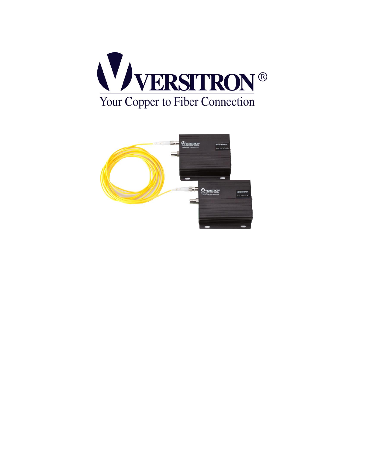
© January 2017
VERSITRON, Inc.
83 Albe Drive / Suite C
Newark, DE 19702
www.versitron.com
HD-CVI / AHD / HD-TVI
Video Only
USER’S MANUAL
v1.0
Page 2

1
HD Series
CAUTION!
The fiber optic transmitters contain a laser-emitting diode located in the optical
connector. This device emits invisible infrared electromagnetic radiation that can be
harmful to human eyes. The radiation from this optical connector, if viewed closely
without any protection, may cause instantaneous damage to the retina of the eye. Direct
viewing of this LED should be avoided at all times.
PROPRIETARY DATA
All data in this manual is proprietary and may not be disclosed,
used or duplicated, for procurement or manufacturing purposes,
without prior written permission by VERSITRON.
VERSITRON LIFETIME WARRANTY
All VERSITRON products are covered by a Lifetime Warranty against defects in materials and
workmanship. This coverage is applicable to the original purchaser and is not transferable.
We repair, or at our option, replace parts/products that, during normal usage and operation, are proven to
be defective during the time you own the products, provided that said products and parts are still
manufactured and/or available. Such repair/replacement is subsequent to receipt of your product at our
facility and our diagnostic evaluation and review of the unit. Advance replacements are not provided as
part of the warranty coverage.
This warranty does not cover damage to products caused by misuse, mishandling, power surges, accident,
improper installation, neglect, alteration, improper maintenance, or other causes which are not normal and
customary applications of the products and for which they were not intended. No other warranty is
expressed or implied, and VERSITRON is not liable for direct, indirect, incidental or consequential damages
or losses.
In the unlikely event a warranty issue should arise, simply contact us at 302-894-0699 or 1-800-537-2296
or via email at [email protected] to obtain a Return Material Authorization (RMA) number, along
with instructions for returning your product.
Copyright VERSITRON, Inc. All rights reserved.
All brand and product names are trademarks or registered trademarks of their respective companies.
versitron.com
Page 3

2
HD Series
Table Of Contents
General Information……………………………………………………………3
Introduction…………………………………………………………….. 3
Technical Specifications……………………………………………. 5
Installation Instructions……………………………………….......................7
Installation Procedure………………………………………………. 7
Indicator LEDs………………………………………………………… 8
Troubleshooting…………………………………………………………………9
versitron.com
Page 4
3
HD Series
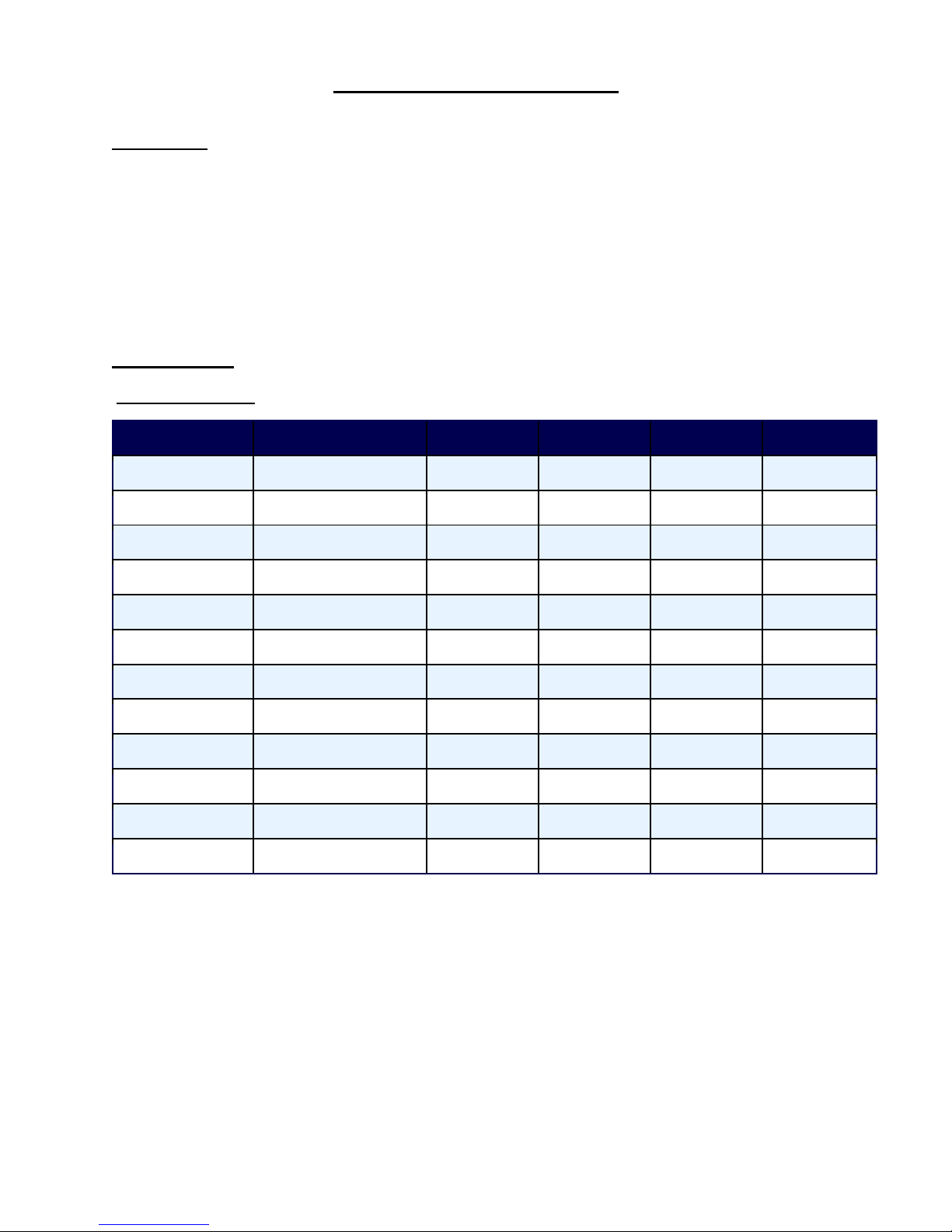
GENERAL INFORMATION
Model
Function
Connector
Fiber Cable
Wavelength
Max Distance
HDCVIT1003
1-Channel Transmitter
ST Simplex
MM
1310nm
2 Km
HDCVIR1003
1-Channel Receiver
ST Simplex
MM
1310nm
2 Km
HDCVIT1005
1-Channel Transmitter
ST Simplex
SM
1310nm
30 Km
HDCVIR1005
1-Channel Receiver
ST Simplex
SM
1310nm
30 Km
HDCVIT2003
2-Channel Transmitter
ST Simplex
MM
1310nm
2 Km
HDCVIR2003
2-Channel Receiver
ST Simplex
MM
1310nm
2 Km
HDCVIT2005
2-Channel Transmitter
ST Simplex
SM
1310nm
30 Km
HDCVIR2005
2-Channel Receiver
ST Simplex
SM
1310nm
30 Km
HDCVIT4003
4-Channel Transmitter
ST Simplex
MM
1310nm
2 Km
HDCVIR4003
4-Channel Receiver
ST Simplex
MM
1310nm
2 Km
HDCVIT4005
4-Channel Transmitter
ST Simplex
SM
1310nm
30 Km
HDCVIR4005
4-Channel Receiver
ST Simplex
SM
1310nm
30 Km
HD-CVI Video Only
Introduction:
The VersiVision HD Series video transmitters and receivers support the highest quality of 8-bit digitally
encoded HD-CVI, AHD or HD-TVI video over one strand of single-mode or multi-mode fiber. Optimized
optical modules; which are compatible with 1280H/25F, 1280H/30F, 1280H/50F, and 1280H/60F, ensure
the highest performance for the most demanding applications. The hot-pluggable and adjustment-free
design ensures the convenience of the installation and operation. The modules are available in either
standalone or rack mount versions.
Model Numbers:
versitron.com
Page 5
4
HD Series
Model
Function
Connector
Fiber Cable
Wavelength
Max Distance
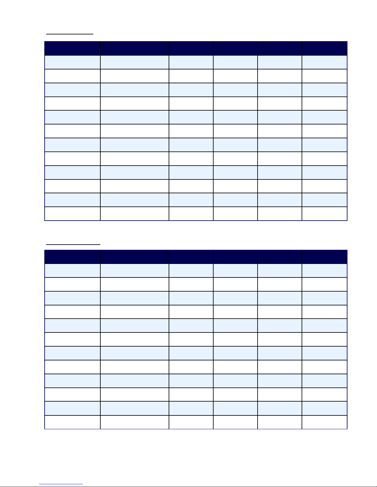
AHDT1003
1-Channel Transmitter
ST Simplex
MM
1310nm
2 Km
AHDR1003
1-Channel Receiver
ST Simplex
MM
1310nm
2 Km
AHDT1005
1-Channel Transmitter
ST Simplex
SM
1310nm
30 Km
AHDR1005
1-Channel Receiver
ST Simplex
SM
1310nm
30 Km
AHDT2003
2-Channel Transmitter
ST Simplex
MM
1310nm
2 Km
AHDR2003
2-Channel Receiver
ST Simplex
MM
1310nm
2 Km
AHDT2005
2-Channel Transmitter
ST Simplex
SM
1310nm
30 Km
AHDR2005
2-Channel Receiver
ST Simplex
SM
1310nm
30 Km
AHDT4003
4-Channel Transmitter
ST Simplex
MM
1310nm
2 Km
AHDR4003
4-Channel Receiver
ST Simplex
MM
1310nm
2 Km
AHDT4005
4-Channel Transmitter
ST Simplex
SM
1310nm
30 Km
AHDR4005
4-Channel Receiver
ST Simplex
SM
1310nm
30 Km
Model
Function
Connector
Fiber Cable
Wavelength
Max Distance
HDTVIT1003
1-Channel Transmitter
ST Simplex
MM
1310nm
2 Km
HDTVIR1003
1-Channel Receiver
ST Simplex
MM
1310nm
2 Km
HDTVIT1005
1-Channel Transmitter
ST Simplex
SM
1310nm
30 Km
HDTVIR1005
1-Channel Receiver
ST Simplex
SM
1310nm
30 Km
HDTVIT2003
2-Channel Transmitter
ST Simplex
MM
1310nm
2 Km
HDTVIR2003
2-Channel Receiver
ST Simplex
MM
1310nm
2 Km
HDTVIT2005
2-Channel Transmitter
ST Simplex
SM
1310nm
30 Km
HDTVIR2005
2-Channel Receiver
ST Simplex
SM
1310nm
30 Km
HDTVIT4003
4-Channel Transmitter
ST Simplex
MM
1310nm
2 Km
HDTVIR4003
4-Channel Receiver
ST Simplex
MM
1310nm
2 Km
HDTVIT4005
4-Channel Transmitter
ST Simplex
SM
1310nm
30 Km
HDTVIR4005
4-Channel Receiver
ST Simplex
SM
1310nm
30 Km
AHD Video Only
HD-TVI Video Only
versitron.com
Page 6

5
HD Series
VIDEO
Video Input:
0.6 ~ 2.0 Volt pk-pk (75 Ohms)
Input/Output Channels:
1, 2, & 4
Bandwidth:
5 Hz - 8MHz
Bit Resolution:
8-Bit
Differential Gain:
< ±1%
Differential Phase:
< ±1°
Tilt:
< 1%
S/N Ratio:
60dB (Weighted)
WAVELEGNTH
Multi-Mode:
1310nm
Single-Mode:
1310nm
OPTICAL EMITTER
Laser Diode
Number of Fibers:
1
CONNECTORS
Optical:
ST
Video:
BNC
GENERAL
Power Supply:
5VDC, 2A
Dimensions (Inches):
1-Channel Units: 4.33 x 4.09 x 1.10
2-Channel Units: 4.33 x 4.09 x 1.10
4-Channel Units: 5.98 x 5.12 x 1.13
MTBF:
> 100,000 Hours
Operating Temperature:
-35° C to +65° C
Storage Temperature:
-45° C to +85° C
Relative Humidity:
0% to 95% (non-condensing)
Technical Specifications
versitron.com
Page 7

6
HD Series
Optical Power Budget
Fiber
Wavelength
Transmitter Output
Receiver Sensitivity
Optical Power Budget
Single-mode
1310nm
-5 dBm
-26 dBm
21 dB
Multi-mode
1310nm
-10 dBm
-24 dBm
14 dB
CAUTION!
The fiber optic transmitters contain a laser-emitting diode located in the optical
connector. This device emits invisible infrared electromagnetic radiation that can be
harmful to human eyes. The radiation from this optical connector, if viewed closely
without any protection, may cause instantaneous damage to the retina of the eye. Direct
viewing of this LED should be avoided at all times.
Optical transmission distance is limited to optical loss of the fiber and additional loss caused by
connectors, splices, and patch panels.
versitron.com
Page 8

7
HD Series
INSTALLATION INSTRUCTIONS
Installation Procedure:
The HD series units are preset for immediate use. There are indicator LEDs on the units for monitoring the
real-time status of power and video. The following instructions describe the typical installation procedure
and the function of the LED indicators located on each unit.
1. Connect the HD video source to the BNC connector on the transmitter using coaxial cable.
2. Connect the BNC connector on the receiver unit to HD video monitor using coaxial cable.
3. Connect the fiber optic cable between the transmitter and receiver.
4. Apply the power supply to both the transmitter and receiver.
5. The system should now be operational.
versitron.com
Page 9
8
HD Series
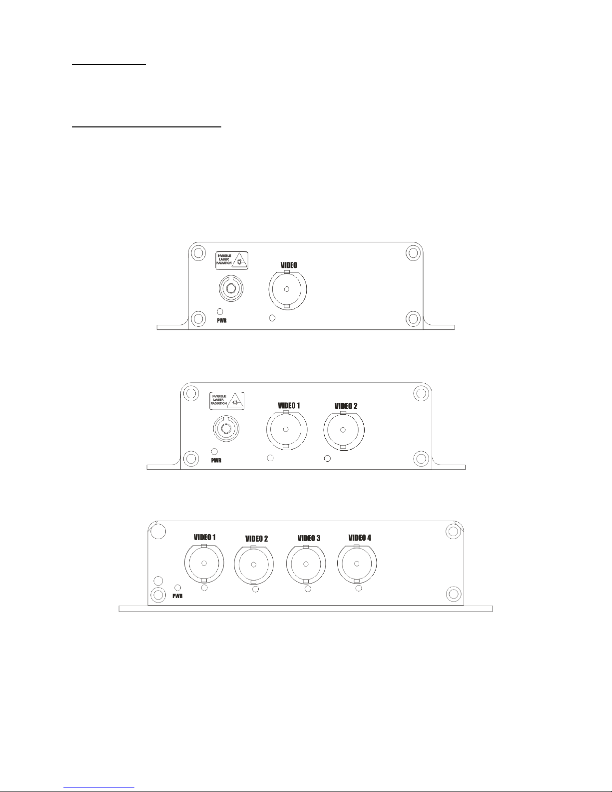
1-Channel Units
2-Channel Units
4-Channel Units
Indicator LEDs:
Each unit has integral LEDs that are used to monitor the state of the unit. Below are descriptions for each.
TRANSMITTER and RECEIVER:
Power: ON (Green): Indicates power has been applied.
Video : OFF: Indicates no video signal present on the BNC connector.
ON (Green): Indicates video signal present on the BNC connector.
versitron.com
Page 10

9
HD Series
TROUBLESHOOTING
Please make sure that the transmitter and the receiver are not used in opposite position.
Optical Fiber
The HD Series is available for most applications using multi-mode or single-mode optical fiber.
Be certain that the attenuation and bandwidth of the fiber optic cable being used is within the range of the
system’s loss budget specifications.
General
Any dirt or dust may easily pollute or block the fiber optic cable from accepting/transmitting light. Therefore,
please try to keep the optical connector clear and always use the dust cap whenever the connector is
exposed to air. It is suggested that the tip of the optical fiber be carefully cleaned with a lint-free cloth
moistened with alcohol from time to time.
The status of any of the LEDs should provide the first clue as to the origin of any operational failure.
versitron.com
 Loading...