

Page 1

VersiVision
FVT1100/FVR1100 Series
Fiber Optic Video Modems
Technical Manual
Also covers FVR1100M modules
Copyright Aug 2005
VERSITRON, Inc.
83 Albe Drive / Suite C
Newark, DE 19702
www.versitron.com
1 www.versitron.com
Page 2

PROPRIETARY DATA
All data in this manual is proprietary and may not be disclosed,
used or duplicated, for procurement or manufacturing purposes,
without prior written permission by
VERSITRON, Inc
.
WARRANTY
All VERSITRON products are warranted against defects in materials and workmanship for one year from date of
delivery. We will repair or, at our option, replace parts, which during normal usage prove to be defective during the
warranty period provided that:
1. You call VERSITRON at (302) 894-0699 or (800) 537-2296 and obtain a Return Maintenance Authorization (RMA)
Number. Please reference your RMA number on the outside of the shipping box.
2. Shipping charges are pre-paid.
No other warranty is expressed or implied and we are not liable for consequential damages. For repairs outside of the
warranty period, the same procedure must be followed.
2 www.versitron.com
Page 3

TABLE OF CONTENTS
SECTION 1: GENERAL DESCRIPTION
INTRODUCTION…………………………………………………………………….4
DESCRIPTION OF EQUIPMENT…………………………………………………...4
FUNCTIONAL CHARACTERISTICS……………………………………………....5
PHYSICAL CHARACTERISTICS……………………………………………..........5
SPECIFICATIONS…………………………………………………………..........5-6
SECTION 2: INSTALLATION
INSTALLATION PROCEDURE……………………………………………………7
SYSTEM DIP SWITCH SETTINGS………………………………………………..8
SYSTEM TERMINAL BLOCK CONNECTIONS……………................................8
INDICATOR LEDs………………………………………………………………….9
TRANSMITTER AND RECEIVER…………………………………………………9
SECTION 3: TROUBLESHOOTING
OPTICAL FIBER………………………………………………………………….10
GENERAL……………………………………………………………………........10
DATA LINK……………………………………………………………………….10
LIST OF ILLUSTRATIONS
FIGURE 1: FVT1103 and FVR1103……………………………………………….5
FIGURE 2: PSACV1 Power Supply………………………………………………..7
FIGURE 3: VCA1100 Data Cable………………………………………………….7
3 www.versitron.com
Page 4
SECTION 1
GENERAL DESCRIPTION
INTRODUCTION
This manual provides information on the installation and operation of the VersiVision
FVT1100/FVR1100 Series Fiber Optic Video Modems. Section 1 contains a general description of the
equipment. Section 2 contains installation instructions. Section 3 contains maintenance and
troubleshooting information.
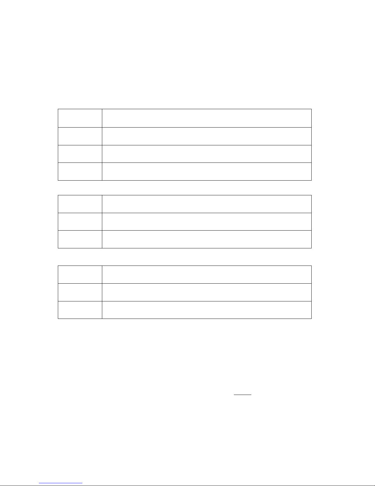
Model
Number
FVT1103
FVT1104
FVT1105
FVR1103
FVR1104
FVR1105
Transmitter; 1-channel simplex video + 1-channel return data;
Multimode; ST; 3km standalone
Transmitter; 1-channel simplex video + 1-channel return data;
Multimode; SC; 3km standalone
Transmitter; 1-channel simplex video + 1-channel return data;
Singlemode; SC; 30km standalone
Receiver; 1-channel simplex video + 1-channel return data;
Multimode; ST; 3km standalone
Receiver; 1-channel simplex video + 1-channel return data;
Multimode; SC; 3km standalone
Receiver; 1-channel simplex video + 1-channel return data;
Singlemode; SC; 30km standalone
Description
FVR1103M
FVR1104M
FVR1105M
Receiver module; 1-channel simplex video + 1-channel return data;
Multimode; ST; 3km; installed in Model FVC14 chassis
Receiver module; 1-channel simplex video + 1-channel return data;
Multimode; SC; 3km; installed in Model FVC14 chassis
Receiver module; 1-channel simplex video + 1-channel return data;
Singlemode; SC; 30km; installed in Model FVC14 chassis
DESCRIPTION OF EQUIPMENT
Functional Characteristics
The VersiVision FVT1100 and FVR1100 Series Fiber Optic Video Modems are used to extend a
frequency modulation (FM) video signal and return data over a single
fiber optic cable. These modems
provide high quality transmission of one channel simplex video and one channel return data at distances to
3km using multimode fiber and distances to 30km using singlemode fiber. A BNC connector provides the
copper interface for the video input/output and a DB9 connector provides the copper interface for the data
input/output. RS-422, RS-485, and RS-232 data interfaces are supported. ST and SC optical connectors
are standard for the fiber optic interface. The FVT1100 and FVR1100 video modems are completely
compatible with NTSC, PAL, or SECAM video standards.
4 www.versitron.com
Page 5

VERSITRON FVT1100 and FVR1100 Series Fiber Optic Video Modems utilize APC circuitry
while maintaining stable optical power output. The fiber optic link established between the transmitter and
receiver devices insures immunity from EMI, RFI, and ground loops. AD, Pelco, Phillips, and Vicon
communication protocols are supported. The data interface is switch-selectable to assure compatibility
with cameras utilizing RS-422, RS-485, or RS-232 data protocols for their PTZ (pan, tilt, zoom) features.
The plug and play design of the FVT1100 transmitters and FVR1100 receivers means no user adjustments
are required. LED status indicators include video sync present (VD), data transmitted (TD), data received
(RD), and power on (PWR)
Physical Characteristics
The VersiVision FVT1100 transmitter and FVR1100 receiver modems are available as standalone
devices for easy plug and play installation. In addition, the FVR1100 receiver modems can be ordered as
circuit card modules (See Chart Above) for installation in the Model FVC14 rack-mount chassis. The
14-slot chassis fits in a standard 19” rack and is offered with either 110VAC or 220VAC power supplies.
The dimensions of the FVT1100 and FVR1100 standalone devices are 7.5in (L) x 6.3in (W) x 1.2in (H).
FIGURE 1: FVT1103 and FVR1103
SPECIFICATIONS
VIDEO
Video Input: 1 volt pk-pk (75 ohms)
Bandwidth: 5 Hz – 8 MHz
Differential Gain: <3 %
Differential Phase: <3˚
Tilt: <2 %
Signal-to-Noise Ratio: 60dB
5 www.versitron.com
Page 6

DATA
Data Interface RS-485, RS-232
Data Rate 100kbps
Bit Error Rate 10
-9
WAVELENGTH 1310nm Singlemode
1310nm Multimode
NUMBER OF FIBERS 1
CONNECTORS
Optical: ST, SC
Video: BNC
Data: DB9F
ENVIRONMENTAL
MTBF >100,000 hours
Operating Temp: -30˚C to +50˚C
Storage Temp: -40˚C to +85˚C
Relative Humidity: 0% to 95% (no condensing)
Size: 19 x 16 x 3.2 cm
7.5 x 6.3 x 1.2 in.
Shipping Weight: <4.4kg
Construction: Aluminum
Finish: Black Paint
INDICATOR
Module
Green Video Sync Present
Red Power On
Blue Data Transmitted/Received
OPTICAL POWER BUDGET
Fiber Wavelength
Transmitter Receiver
Model (s) Output Model Sensitivity
Multimode 1310nm FVT1103
FVT1104
-10dBm FVR1103
FVR1104
-30dBm 20dB 3km
Optical
Power
Budget
Max Distance
Singlemode 1310nm/1550nm FVT1105 -10dBm FVR1105 -35dBm 25dB 30km
*Optical transmission distance is limited to optical loss of the fiber and additional loss caused by
connectors, splices, and patch panels.
6 www.versitron.com
Page 7
CAUTION!
The transmitter unit contains a light-emitting diode located in the optical connector. This device emits
invisible infrared electromagnetic radiation that can be harmful to human eyes. The radiation from this
optical connector, if viewed closely without any protection, may cause instantaneous damage to the retina
of the eye. Direct viewing of this LED should be avoided at all times.
SECTION 2
INSTALLATION INSTRUCTIONS
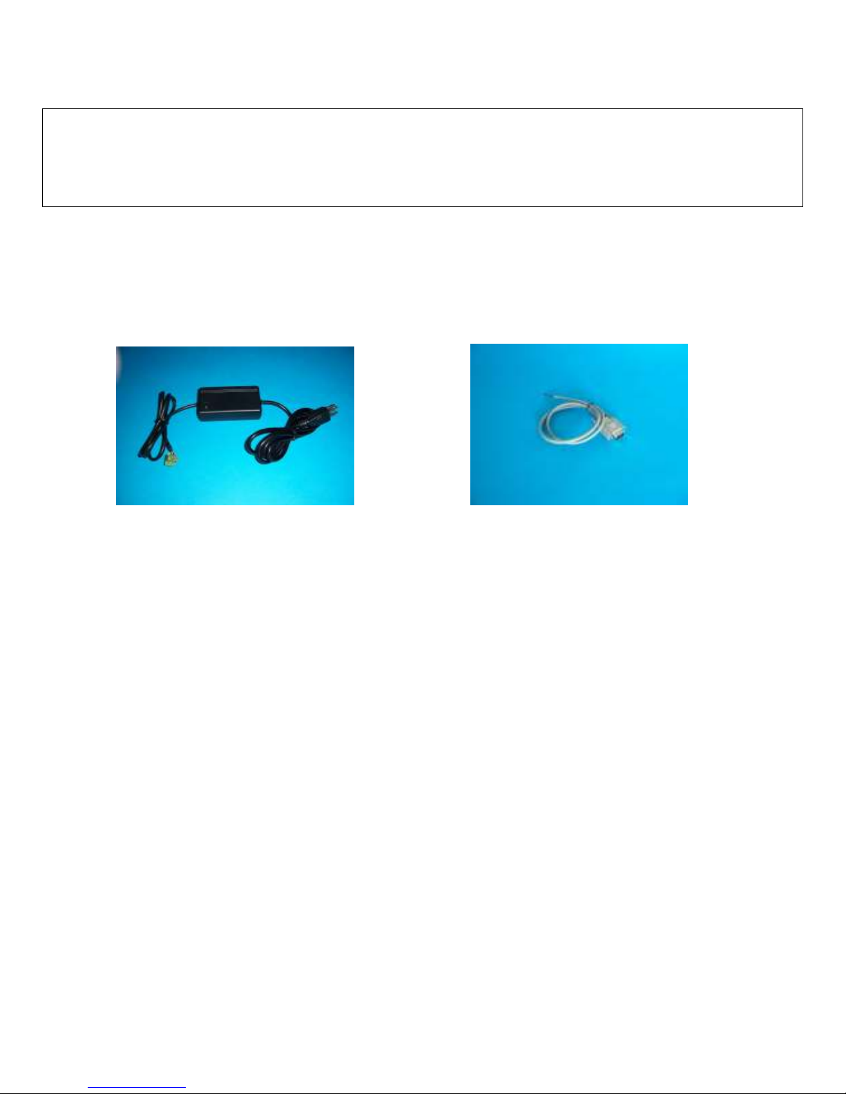
FIGURE 2: PSACV1 Power Supply FIGURE 3: VCA1100 Data Cable
INSTALLATION PROCEDURE
The VersiVision FVT1100 and FVR1100 Series fiber optic video modems can be used with RS-485/RS-422
and RS-232 data protocols. Simply set the mode of operation with the internal DIP switches and then connect
the signal, power supply, and fiber optic cables between the two units. There are indicator LEDs on the units for
monitoring the real-time status of video, power, and data. The following instructions describe the typical
installation procedure and the function of the LED indicators located on each unit.
1. Connect the video source (camera) to the video input BNC connector on the FVT1100 transmitter unit
using coaxial cable.
2. Connect the video output BNC connector on the FVR1100 receiver unit to the video monitor using
coaxial cable.
3. Connect the fiber optic cable between the transmitter and receiver devices.
4. See page 8 for instructions on connecting the data cable
5. Apply the power supply to both the transmitter and receiver using the PSACV1 power supply provided.
Note: If using any of the FVR1100M modules, power is provided from the integral power supply of the
FVC14 chassis.
6. When the power is applied, the red POWER LED will light, indicating the presence of operating power.
The green VIDEO LED and the blue DATA LED will give an indication as stated in the following page.
7. The link should now be operational.
7 www.versitron.com
Page 8

SYSTEM DIP SWITCH SETTINGS
The data interface circuit used in this product has internal switches that are used to configure the various signal
options. These are preset to RS-485 at the time of shipment. If changes are required, the positions of these
switches must be changed in accordance with the following table.
Protocol 1 2 3 4
RS-485/RS-422 On Off Not Used Off
RS-232 Off On Not Used Off
RS-485 Bus Matching Off Off Not Used On
*Note: RS-485 Bus Matching: When the switch is on, then 120 Ohm termination is applied which
matches the twisted pair cable impedance.
SYSTEM TERMINAL BLOCK CONNECTIONS
The various input and output connections for the VersiVision FVT1100 and FVR1100 Series modems are as
follows:
Video Input or Output: BNC Connectors
Data Input/Output Connector:
RS-485 2-wire
Red Wire: Signal being transmitted or received (+) over fiber
Blue Wire: Signal being transmitted or received (-) over fiber
RS-485 Connection
Camera Site
Using the VCA1100 data cable provided, plug the DB9 connector into the DB9 port on the FVT1100
transmitter. Connect the Red wire (485A) in the data cable from the FVT1100 transmitter to RS-485 (+) of the
controlled unit (pan/tilt, dome), and connect the Blue wire (485B) to RS-485 (-) of the controlled unit (pan/tilt,
zoom).
Control Site
Using the VCA1100 data cable provided, plug the DB9 connector into the DB9 port on the FVR1100 receiver.
Connect the Red wire (485A) in the data cable from the FVR1100receiver to RS-485 (+) of the controlling unit
(Keyboard Controller, Matrix, DVR), and connect the Blue wire (485B) to RS-485 (-) of the controlling unit
(Keyboard Controller, Matrix, DVR).
RS-232
Green Wire: Signal being transmitted out over fiber
Yellow Wire: Signal being received in from fiber
Purple Wire: Ground
8 www.versitron.com
Page 9

RS-232 Connection
Camera Site
Using the VCA1100 data cable provided, plug the DB9 connector into the DB9 port on the FVT1100
transmitter. Connect the Yellow wire (232T) in the data cable from the FVT1100 transmitter to the RS-232 port
of the controlled unit (pan/tilt, zoom). The Purple wire (GND) is used for ground connection.
Control Site
Using the VCA1100 data cable provided, plug the DB9 connector into the DB9 port on the FVR1100 receiver.
Connect the Green wire (232R) in the data cable from the FVT1100 receiver to the RS-232 port of the
controlling unit (Keyboard Controller, Matrix, DVR). The Purple wire (GND) is used for ground connection.
INDICATOR LEDs
The stand-alone units have integral LEDs that are used to monitor the state of the unit. There is one video LED,
one power LED, and one data LED on each unit. One, labeled as “Power (or PWR)”, lights when operating
power is present. Another, labeled as “Video (or VID)”, lights when the video input/output signals are detected.
The other one, labeled as “TD or RD”, blinks at the rate of the operating data.
TRANSMITTER and RECEIVER
Power: ON: (Red) indicates that correct power has been applied
Transmitter:
Video: OFF: Indicates no video detected on input BNC connector
(No Video present on input BNC)
ON: (Green) Indicates video detected on input BNC connector
(Video present on input BNC connector)
Data: OFF: Indicates no data detected on the transmit data cable
Blinking: (Blue) Indicates data transmitted at the rate of the operation data.
Receiver:
Video: OFF: Indicates no video detected on output BNC connector
(No video present on output BNC)
ON: (Green) Indicates video detected on output BNC connector
(Video present on input BNC)
Data: OFF: Indicates no data detected on the receive data cable
Blinking: (Blue) Indicates data received at the rate of the operation data.
9 www.versitron.com
Page 10

SECTION 3
TROUBLESHOOTING
OPTICAL FIBER
The VersiVision FVT1100 and FVR1100 Series fiber optic video modems are available for applications using
multimode or singlemode optical fibers. Please be certain that the correct size and type of the fiber is being used
for the particular mode transmitter/receiver combination.
Also be certain that the attenuation and bandwidth of the fiber optic cable being used is within the range of the
system’s loss budget specifications.
GENERAL
Any dirt or dust may easily pollute or block the fiber from accepting or radiating light. Therefore, please try to
keep the optical connector clear and always use the dust caps whenever the connector is exposed to air. It is
suggested that the tip of the optical connector should be carefully cleaned with a lint-free cloth moistened with
alcohol from time to time.
The status of any of the VIDEO LED should provide the first clue as to the origin of any operational failure. If
the VIDEO LED on the receiver unit is off, it usually means that the fiber is broken or has too much attenuation.
Next, be certain to check all connections and assure that inputs and outputs are not intermixed and the
transmitter and receiver are not connected incorrectly.
DATA LINK
Even when installed exactly as directed, it is possible that the data function may fail to operate properly. If these
problems occur, first check the data cable, then check that the data cable connector is firmly inserted into the
data interface. Finally, swap the Red Wire (Transmit +) and Blue Wire (Transmit -) pins and then do the same
for the Red Wire (Receive +) and Blue Wire (Receive -) pins. Make sure to do this on both the transmitter and
receiver units.
RS-485 Pin Definition:
The RS-485(+) (Red Wire) should be connected to Pin 5 of the DB9F connector, while the RS-485(-) (Blue
Wire) should be connected to Pin 4 of the DB connector. (The pin numbers are embossed on the connector).
RS-232 Pin Definition:
The RS-232R (Green Wire) should be connected to Pin 1 of the DB9F connector while the RS-232T (Yellow
Wire) should be connected to Pin 2 of the DB connector, and the GROUND (Purple Wire) should be connected
to Pin 3 of the DB connector.
Note: If the system is still not working after examining the above possibilities, please contact our Customer
Service Department for further assistance.
10 www.versitron.com
Page 11
11 www.versitron.com
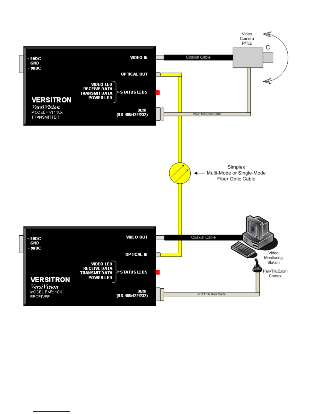
FIGURE 4:
VersiVision FVT110x/FVR110x
Connection Layout
 Loading...