

Versitron Web Smart+ SG71070M User Manual
UUsseer
r
’
’
ss MMaannuuaal
l
vv11..000
0
© November 2016
VERSITRON, Inc.
83 Albe Drive / Suite C
Newark, DE 19702
www.versitron.com
SG71070M
10-Port 10/100/1000
Web Smart+ Managed Switch
with 1G/10G SFP Slots
i
SG71070M
Revision A3

Copyright VERSITRON, Inc. All rights reserved. All brand and product names are trademarks or registered
trademarks of their respective companies.
PROPRIETARY DATA
All data in this manual is proprietary and may not be disclosed,
used or duplicated, for procurement or manufacturing purposes,
without prior written permission by VERSITRON.
VERSITRON LIFETIME WARRANTY
All VERSITRON products are covered by a Lifetime Warranty against defects in materials and
workmanship. This coverage is applicable to the original purchaser and is not transferable.
We repair, or at our option, replace parts/products that, during normal usage and operation, are proven
to be defective during the time you own the products, provided that said products and parts are still
manufactured and/or available. Such repair/replacement is subsequent to receipt of your product at
our facility and our diagnostic evaluation and review of the unit. Advance replacements are not
provided as part of the warranty coverage.
This warranty does not cover damage to products caused by misuse, mishandling, power surges,
accident, improper installation, neglect, alteration, improper maintenance, or other causes which are
not normal and customary applications of the products and for which they were not intended. No
other warranty is expressed or implied, and VERSITRON is not liable for direct, indirect, incidental or
consequential damages or losses.
In the unlikely event a warranty issue should arise, simply contact us at 302-894-0699 or
1-800-537-2296 or via email at fiberlink@versitron.com to obtain a Return Material Authorization (RMA)
number, along with instructions for returning your product.
ii
SG71070M
Revision A3
NOTE: Emphasizes important information or calls your
attention to related features or instructions.
W
ARNING
:
Alerts you to potential hazard that could cause
personal injury.
C
AUTION
:
Alerts you to a potential hazard that could cause
loss of data, or damage the system or equipment.
Copyright
Purpose
Audience
Conventions
About This Manual
Copyright © 2016 VERSITRON, Inc. All rights reserved.
The products and programs described in this manual are licensed products of
VERSITRON, Inc. This manual contains proprietary information protected by copyright,
and this manual and all accompanying hardware, software and documentation are
copyrighted. No parts of this manual may be copied, photocopied, reproduced,
translated or reduced to any electronic medium or machine-readable from by any
means by electronic or mechanical. Including photocopying, recording, or information
storage and retrieval systems, for any purpose other than the purchaser’s personal use,
and without the prior express written permission of VERSITRON, Inc.
This manual gives specific information on how to operate and use the management
functions of the SG71070M
The Manual is intended for use by network administrators who are responsible for
operating and maintaining network equipment; consequently, it assumes a basic
working knowledge of general switch functions, the Internet Protocol (IP), and Simple
Network Management Protocol (SNMP).
The following conventions are used throughout this manual to show information.
Warranty
See the VERSITRON, Inc. warranty statement.
Disclaimer
VERSITRON, Inc. does not warrant that the hardware will work properly in all
environments and applications, and marks no warranty and representation, either
implied or expressed, with respect to the quality, performance, merchantability, or
fitness for a particular purpose. VERSITRON, Inc. disclaims liability for any inaccuracies
or omissions that may have occurred. Information in this User’s Manual is subject to
change without notice and does not represent a commitment on the part of
VERSITRON, Inc.. VERSITRON, Inc. assumes no responsibility for any inaccuracies that
may be contained in this User’s Manual. VERSITRON, Inc. makes no commitment to
update or keep current the information in this User’s Manual, and reserves the righter
to make improvements to this User’s Manual and /or to the products described in this
User’s Manual, at any time without notice.
iii
SG71070M
Revision A3

Table of Contents
Revision History .............................................................................................................................................. vi
INTRODUCTION ..................................................................................................................... 1
CHAPTER 1 OPERATION OF WEB-BASED MANAGEMENT ................................... 2
CHAPTER 2 SYSTEM CONFIGURATION ..................................................................... 3
2-1 System ..................................................................................................................................................... 3
2-1.1 Information ............................................................................................................................................. 3
2-1.2 IP .............................................................................................................................................................. 4
2-1.3 NTP .......................................................................................................................................................... 7
2-1.4 Time ......................................................................................................................................................... 9
2-1.5 Log ......................................................................................................................................................... 11
2-2 Ports Configuration ............................................................................................................................ 12
2-2.1 Ports ...................................................................................................................................................... 12
2-3 DHCP ..................................................................................................................................................... 14
2-3.1 Snooping .............................................................................................................................................. 14
2-4 Security ................................................................................................................................................. 15
2-4.1 Switch .................................................................................................................................................... 15
2-4.1.1 Users .............................................................................................................................................. 15
2-4.2 Network ................................................................................................................................................ 17
2-4.2.1 Access Control List ....................................................................................................................... 17
2-4.2.2 IP Source Guard ........................................................................................................................... 21
2-4.2.3 ARP Inspection ............................................................................................................................. 23
2-5 Aggregation ......................................................................................................................................... 27
2-5.1 Port ........................................................................................................................................................ 27
2-5.2 Aggregator View .................................................................................................................................. 29
2-5.3 Aggregation Hash Mode .................................................................................................................... 30
2-5.4 LACP System Priority ........................................................................................................................... 31
2-6 MSTP ..................................................................................................................................................... 32
2-6.1 Status ..................................................................................................................................................... 32
2-6.2 Region Config ...................................................................................................................................... 33
2-6.3 Instance View ....................................................................................................................................... 34
2-7 IPMC Profile ......................................................................................................................................... 40
2-7.1 Profile Table .......................................................................................................................................... 40
2-7.1.1 IPMC Profile Rule Settings Table ................................................................................................ 41
2-7.2 Address Entry ....................................................................................................................................... 43
2-8 MAC Table ............................................................................................................................................ 44
2-9 IGMP Snooping ................................................................................................................................... 47
2-9.1 Basic Configuration ............................................................................................................................. 47
2-9.2 VLAN Configuration ............................................................................................................................ 49
iv
SG71070M
Revision A3

2-9.3 Filtering Profile ..................................................................................................................................... 51
2-10 VLANS ................................................................................................................................................. 52
2-11 Private VLANS ................................................................................................................................... 56
2-11.1 VLAN Membership ............................................................................................................................ 56
2-11.2 Port Isolation ...................................................................................................................................... 57
2-12 VCL ...................................................................................................................................................... 58
2-12.1 MAC-based VLAN.............................................................................................................................. 58
2-12.2 Protocol -based VLAN ...................................................................................................................... 59
2-12.2.1 Group to VLAN ........................................................................................................................... 59
2-12.2.2 Protocol to Group ...................................................................................................................... 60
2-12.3 IP Subnet-based VLAN ..................................................................................................................... 62
2-13 QoS ...................................................................................................................................................... 63
2-13.1 Port Classification .............................................................................................................................. 63
2-13.2 Port Policing ....................................................................................................................................... 65
2-13.3 Port Shaper ......................................................................................................................................... 66
2-13.4 Port Scheduler.................................................................................................................................... 68
2-13.5 Port Tag Classification ....................................................................................................................... 70
2-13.6 Port Tag Remarking ........................................................................................................................... 71
2-13.7 DSCP Translation................................................................................................................................ 72
2-13.8 Storm Control ..................................................................................................................................... 73
2-13.9 WRED .................................................................................................................................................. 74
2-13.9.1 Basic Configuration ................................................................................................................... 74
2-13.9.2 Configuration ............................................................................................................................. 75
2-14 Mirror .................................................................................................................................................. 77
2-15 UPnP ................................................................................................................................................... 79
2-16 Loop Protection ................................................................................................................................. 80
CHAPTER 3 MONITOR ................................................................................................. 82
3-1 System ................................................................................................................................................... 82
3-1.1 Information ........................................................................................................................................... 82
3-1.2 IP Status ................................................................................................................................................ 84
3-1.3 Log ......................................................................................................................................................... 86
3-2 Ports ...................................................................................................................................................... 87
3-2.1 Traffic Overview ................................................................................................................................... 87
3-2.2 Detailed Statistics ................................................................................................................................ 88
3-3 DHCP ..................................................................................................................................................... 91
3-3.1 Snooping Table .................................................................................................................................... 91
3-4 Security ................................................................................................................................................. 92
3-4.1 Network ................................................................................................................................................ 92
3-4.1.1 IP Source Guard ........................................................................................................................... 92
3-4.1.2 ARP Inspection ............................................................................................................................. 93
3-5 MAC Table ............................................................................................................................................ 94
v
SG71070M
Revision A3

3-6 IGMP Snooping ................................................................................................................................... 96
Release
Date
Revision
0.81.2
07/24/2016
A1
0.82.2
10/06/2016
A2
0.83.2
12/10/2016
A3
3-6.1 Status ..................................................................................................................................................... 96
3-6.2 Group Information ............................................................................................................................... 98
3-6.3 IPv4 SSM Information ......................................................................................................................... 99
3-7 VLANS ................................................................................................................................................. 100
3-7.1 VLAN Membership ............................................................................................................................ 100
3-7.2 VLAN Port ........................................................................................................................................... 101
3-8 Loop Protection ................................................................................................................................. 103
3-9 LLDP .................................................................................................................................................... 104
3-9.1 LLDP information ............................................................................................................................... 104
3-9.2 LLDP-MED Neighbor ......................................................................................................................... 106
3-9.3 LLDP Statistics .................................................................................................................................... 110
CHAPTER 4 DIAGNOSTICS........................................................................................ 112
4-1 Ping ..................................................................................................................................................... 112
4-2 Cable Diagnostics .............................................................................................................................. 113
4-3 Traceroute .......................................................................................................................................... 114
CHAPTER 5 MAINTENANCE ..................................................................................... 115
5-1 Restart Device .................................................................................................................................... 115
5-2 Firmware ............................................................................................................................................. 116
5-2.1 Firmware Upgrade ............................................................................................................................. 116
5-3 Configuration .................................................................................................................................... 117
5-3.1 Save startup-config ........................................................................................................................... 117
Revision History
vi
SG71070M
Revision A3

1
INTRODUCTION
Overview
The SG71070M Web Smart+ Managed Switch is a cost-effective 10GbE Ethernet Switch
offering 10G copper and fiber connections in a small form factor. With the enormous growth of
network traffic and network storage in recent years, 10GbE is becoming a natural upgrade for many
businesses in order to keep up with their network performance and business efficiency demands.
The SG71070M delivers (8) 1G/10G RJ-45 ports and (2) 1G/10G SFP+ ports. It provides higher
bandwidth and reliability for SMB and enterprise applications.
The SG71070M is ideal for providing connection flexibility across a network allowing easier
network integration for virtualization, cloud services, and server-to-server applications that expand
your enterprise network by adding local switching capacity and better scalability. This allows you to
support more high-bandwidth applications such as server farms, TV wall, and digital signage video
streaming, etc.
Web Smart+ features provide easier manageability, basic security and QoS.
IEEE 802.3az EEE Energy Efficient Ethernet standard for green Ethernet.
8.6” wide Small Form Factor Design.
All 10GbE Copper and Fiber Ports.
Auto Fan Control for Better Reliability and Noise Reduction.
Overview of this user’s manual
Chapter 1 “Operation of Web-based Management”
Chapter 2 “System Configuration”
Chapter 3 “Monitor”
Chapter 4 “Diagnostics”
Chapter 5 “Maintenance”
Publication date: Dec., 2015
Revision A3
2
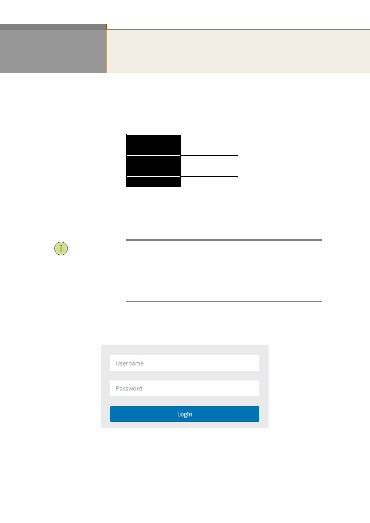
IP Address
192.168.1.1
Subnet Mask
255.255.255.0
Default
192.168.1.254
Username
admin
Password
NOTE:
When you first log into the switch, the username is admin and the password
is blank.
When you log into the SG71070M Web UI management, you can use both
ipv4 or ipv6 login.
To optimize the display effect, we recommend you use Microsoft IE 6.0 or
above, Netscape V7.1 or above or Firefox V1.00 or above, and the resolution
at 1024x768.
Chapter 1 Operation of Web-based Management
Initial
Configuration
This chapter instructs you how to configure and manage the SG71070M through the
web user interface. With this feature, you can easily access and monitor the switch
through any port, including MIBs status, port activity, port aggregation status,
multicast traffic, VLAN and priority status, even illegal access records, etc..
The default values of the SG71070M are listed in the table below:
1. Plug in the power cable
2. Check if the IP address of the computer is within the network segment:
192.168.1.xxx (“xxx” ranges 1~254). For example, 192.168.1.100.
3. Open the Web browser, and enter 192.168.1.1. The login window appears.
Figure 1. The login page
Publication date: Dec, 2015
Revision A3
3
Chapter 2 System Configuration
This chapter describes the basic configuration tasks which include the System Information and any other
settings (e.g. Time, Account, IP, Syslog and SNTP.)
2-1 System
You can identify the system by configuring the contact information, name, and location of the
switch.
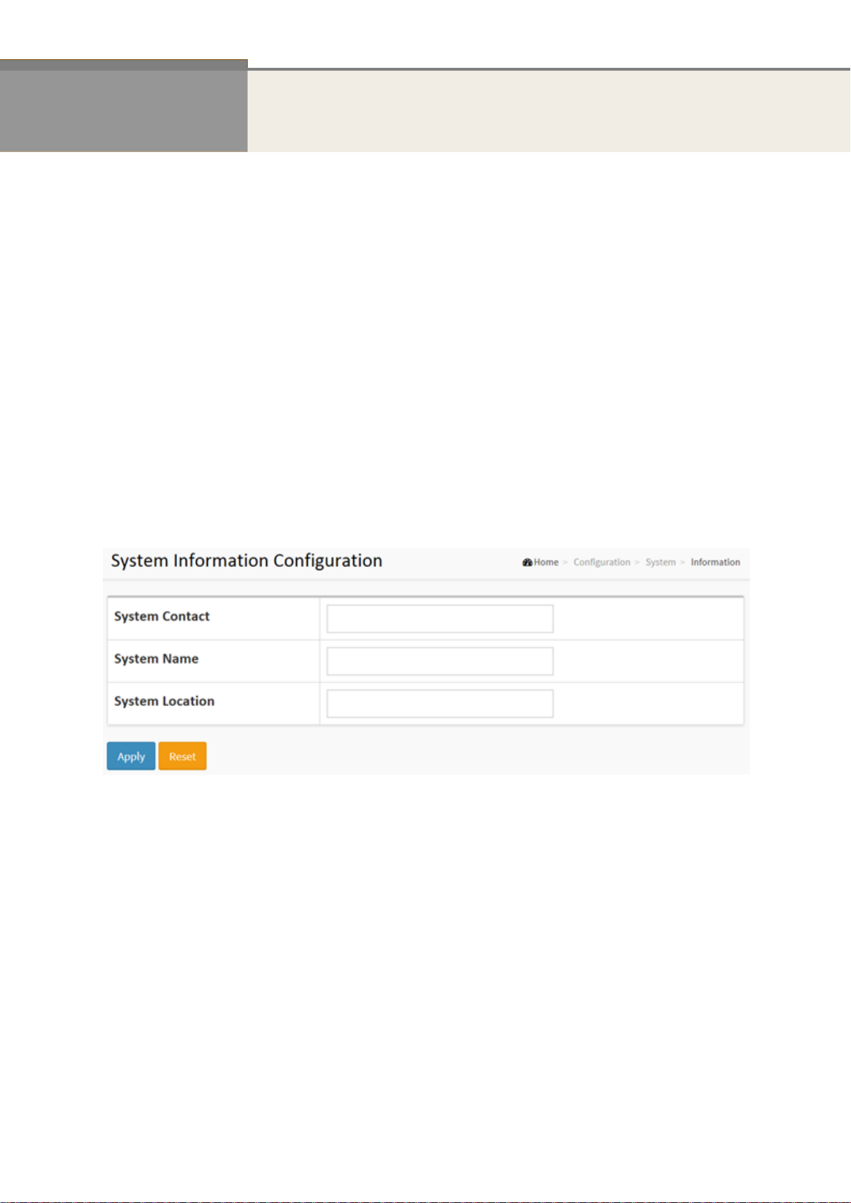
2-1.1 Information
The switch system’s contact information is provided here.
Web interface
To configure System Information configuration in the web interface:
1. Click Configuration, System, and Information.
2. Write System Contact, System Name, System Location information in this page.
3. Click Apply.
Figure 2-1.1: The System Information Configuration
Parameter description:
System Contact:
The textual identification of the contact person for this managed node, together with
information on how to contact this person. The allowed string length is 0 to 128, and the
allowed content is the ASCII characters from 32 to 126.
System Name:
An administratively assigned name for this managed node. By convention, this is the node's
fully-qualified domain name. A domain name is a text string drawn from the alphabet
(A-Za-z), digits (0-9), minus sign (-). No space characters are permitted as part of a name.
The first character must be an alpha character. And the first or last character must not be a
minus sign. The allowed string length is 0 to 128.
System Location:
The physical location of this node (e.g., telephone closet, 3rd floor). The allowed string
length is 0 to 128, and the allowed content is the ASCII characters from 32 to 126.
Publication date: Dec, 2015
Revision A3
2-1.2 IP
The IPv4 address for the switch could be obtained via DHCP Server for VLAN 1. To manually
configure an address, you need to change the switch's default settings to values that are
compatible with your network. You may also need to establish a default gateway between the
switch and management stations that exist on another network segment.
Configure the switch-managed IP information on this page.
Configure IP basic settings, control IP interfaces and IP routes.
The maximum number of interfaces supported is 8 and the maximum number of routes is 32.
Web interface
To configure the IP Configuration in the web interface:
1. Click Configuration, System, IP.
2. Click Add Interface then you can create new Interface on the switch.
3. Click Add Route then you can create new Route on the switch.
4. Click Apply.
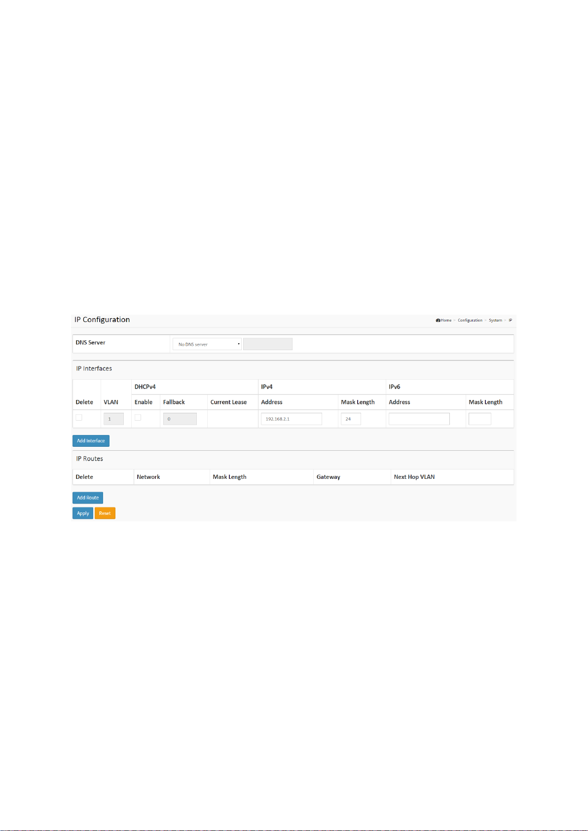
Figure2-1.2: The IP Configuration
Parameter description:
IP Configuration
DNS Server
This setting controls the DNS name resolution done by the switch. The following modes are
supported:
From any DHCP interfaces
The first DNS server offered from a DHCP lease to a DHCP-enabled interface will be
used.
No DNS server
No DNS server will be used.
Configured
Explicitly provide the IP address of the DNS Server in dotted decimal notation.
From this DHCP interface
Specify from which DHCP-enabled interface a provided DNS server should be
preferred.
4
SG71070M
Revision A3

IP Interfaces
Delete
Select this option to delete an existing IP interface.
VLAN
The VLAN associated with the IP interface. Only ports in this VLAN will be able to access the
IP interface. This field is only available for input when creating a new interface.
IPv4 DHCP Enabled
Enable the DHCP client by checking this box. If this option is enabled, the system will
configure the IPv4 address and mask of the interface using the DHCP protocol. The DHCP
client will announce the configured System Name as hostname to provide DNS lookup.
IPv4 DHCP Fallback Timeout
The number of seconds for trying to obtain a DHCP lease. After this period expires, a
configured IPv4 address will be used as IPv4 interface address. A value of zero disables the
fallback mechanism, such that DHCP will keep retrying until a valid lease is obtained. Legal
values are 0 to 4294967295 seconds.
IPv4 DHCP Current Lease
For DHCP interfaces with an active lease, this column show the current interface address, as
provided by the DHCP server.
IPv4 Address
The IPv4 address of the interface in dotted decimal notation.
If DHCP is enabled, this field is not used. The field may also be left blank if IPv4 operation
on the interface is not desired.
IPv4 Mask
The IPv4 network mask, in number of bits (prefix length). Valid values are between 0 and 30
bits for a IPv4 address.
If DHCP is enabled, this field is not used. The field may also be left blank if IPv4 operation
on the interface is not desired.
IPv6 Address
The IPv6 address of the interface. An IPv6 address is in 128-bit records represented as eight
fields of up to four hexadecimal digits with a colon separating each field (:). For example,
fe80::215:c5ff:fe03:4dc7. The symbol :: is a special syntax that can be used as a shorthand
way of representing multiple 16-bit groups of contiguous zeros; but it can appear only once.
It can also represent a legally valid IPv4 address. For example, ::192.1.2.34.
The field may be left blank if IPv6 operation on the interface is not desired.
IPv6 Mask
The IPv6 network mask, in number of bits (prefix length). Valid values are between 1 and
128 bits for a IPv6 address.
The field may be left blank if IPv6 operation on the interface is not desired.
IP Routes
Delete
Select this option to delete an existing IP route.
Network
The destination IP network or host address of this route. Valid format is dotted decimal
notation or a valid IPv6 notation. A default route can use the value 0.0.0.0or IPv6 :: notation.
5
SG71070M
Revision A3

Mask Length
The destination IP network or host mask, in number of bits (prefix length). It defines how
much of a network address that must match, in order to qualify for this route. Valid values
are between 0 and 32 bits respectively 128 for IPv6 routes. Only a default route will have a
mask length of 0 (as it will match anything).
Gateway
The IP address of the IP gateway. Valid format is dotted decimal notation or a valid IPv6
notation. Gateway and Network must be of the same type.
Next Hop VLAN (Only for IPv6)
The VLAN ID (VID) of the specific IPv6 interface associated with the gateway.
The given VID ranges from 1 to 4094 and will be effective only when the corresponding IPv6
interface is valid.
If the IPv6 gateway address is link-local, it must specify the next hop VLAN for the gateway.
If the IPv6 gateway address is not link-local, system ignores the next hop VLAN for the
gateway.
Buttons
Add Interface
Click to add a new IP interface. A maximum of 8 interfaces is supported.
Add Route
Click to add a new IP route. A maximum of 32 routes is supported.
Apply
Click to save changes.
Reset
Click to undo any changes made locally and revert to previously saved values. The physical
location of this node (e.g., telephone closet, 3rd floor). The allowed string length is 0 to 128,
and the allowed content is the ASCII characters from 32 to 126.
6
SG71070M
Revision A3
2-1.3 NTP
NTP is Network Time Protocol and is used to sync the network time based on Greenwich Mean
Time (GMT). If you use the NTP mode and select a built-in NTP time server or manually specify
a user-defined NTP server as well as Time Zone, the switch will sync the time shortly after
pressing the <Apply> button. Though it synchronizes the time automatically, NTP does not
update the time periodically without user processing.
Time Zone is an offset time off GMT. You have to select the time zone first and then perform
time sync via NTP because the switch will combine this time zone offset and updated NTP time
to set the local time. Otherwise, you will not able to get the correct time. The switch supports
configurable time zone from –12 to +13 step 1 hour.
Default Time zone: +8 Hrs.
Web interface
To configure SNTP Configuration in the web interface:
1. Click Configuration, System and NTP.
2. Specify the Time parameter in manual parameters.
3. Click Apply.
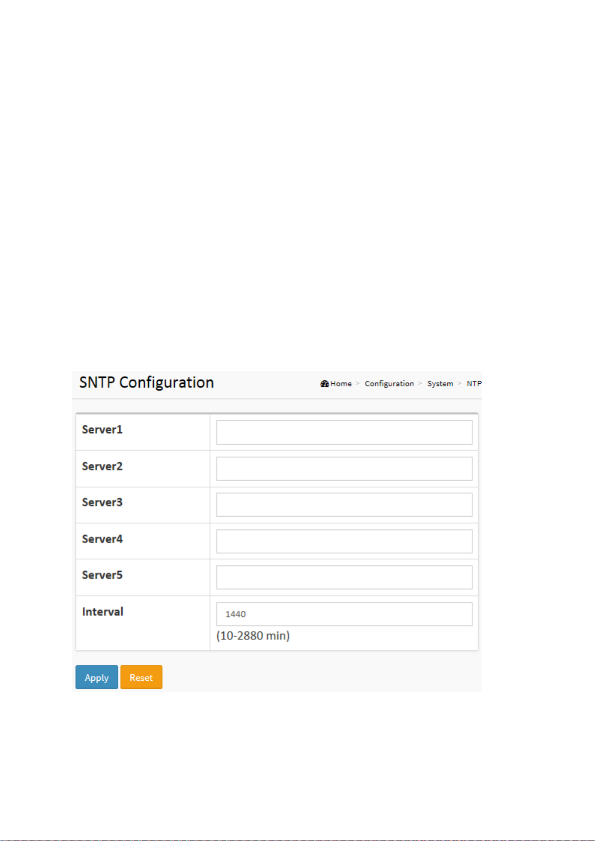
Figure 2-1.3: The SNTP Configuration
Parameter description:
Server 1 to 5
Provide the SNTP IPv4 or IPv6 address of this switch. IPv6 address is in 128-bit records
represented as eight fields of up to four hexadecimal digits with a colon separating each
field (:). For example, 'fe80::215:c5ff:fe03:4dc7'. The symbol '::' is a special syntax that can be
used as a shorthand way of representing multiple 16-bit groups of contiguous zeros; but it

can only appear once. It can also represent a legally valid IPv4 address. For example,
'::192.1.2.34'.
Buttons
These buttons are displayed on the NTP page:
Apply – Click to save changes.
Reset - Click to undo any changes made locally and revert to previously saved values.
8
SG71070M
Revision A3
2-1.4 Time
The switch provides manual and automatic ways to set the system time via NTP. Manual setting
is simple and you just input “Year”, “Month”, “Day”, “Hour” and “Minute” within the valid value
range indicated in each item.
Web interface
To configure Time Configuration in the web interface:
1. Click Configuration, System and Time.
2. Specify the Time parameter in manual parameters.
3. Click Apply.
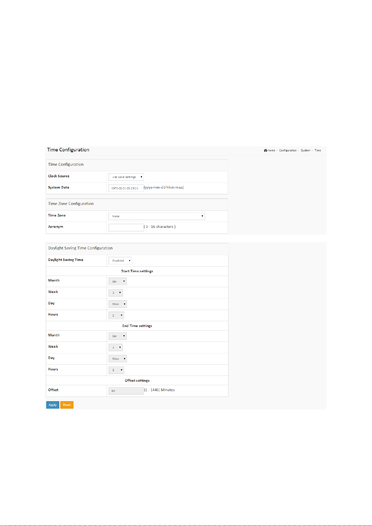
Figure 2-1.4: The Time Configuration
Parameter description:
Time Configuration
Clock Source
There are two modes for configuring how the Clock Source from. Select "Use Local Settings”:
Clock Source from Local Time. Select "Use NTP Server”: Clock Source from NTP Server.
System Date
9
SG71070M
Revision A3

Show the current time of the system. The year of system date limits between 2011 and 2037.
NOTE: The “Start Time Settings” and “End Time Settings” are
displayed based on what you set in the “Start Time Settings” and “End
Time Settings” fields.
Time Zone Configuration
Time Zone
Lists various Time Zones worldwide. Select appropriate Time Zone from the drop down and
click Apply to set.
Acronym
User can set the acronym of the time zone. This is a User configurable acronym to identify
the time zone. (Range: Up to 16 characters)
Daylight Saving Time Configuration
Daylight Saving Time
This is used to set the clock forward or backward according to the configurations set below
for a defined Daylight Saving Time duration. Select 'Disable' to disable the Daylight Saving
Time configuration. Select 'Recurring' and configure the Daylight Saving Time duration to
repeat the configuration every year. Select 'Non-Recurring' and configure the Daylight
Saving Time duration for single time configuration. (Default: Disabled).
Recurring Configuration
Start time settings
Week - Select the starting week number.
Day - Select the starting day.
Month - Select the starting month.
Hours - Select the starting hour.
Minutes - Select the starting minute.
End time settings
Week - Select the ending week number.
Day - Select the ending day.
Month - Select the ending month.
Hours - Select the ending hour.
Offset settings
Offset - Enter the number of minutes to add during Daylight Saving Time. (Range: 1 to 1440)
Buttons
These buttons are displayed on the Time page:
Apply – Click to save changes.
Reset - Click to undo any changes made locally and revert to previously saved values.
10
SG71070M
Revision A3
2-1.5 Log
The log is standard for logging program messages . It allows separation of the software that
generates messages from the system that stores them, and the software that reports and
analyzes them. It can be used as well for generalized information, analysis and debugging
messages. It is supported by a wide variety of devices and receivers across multiple platforms.
Web Interface
To configure System Log Configuration in the web interface:
1. Click Configuration, System and log.
2. Specify the syslog parameters include IP Address of Syslog server and Port number.
3. Evoke the Syslog to enable it.
4. Click Apply.
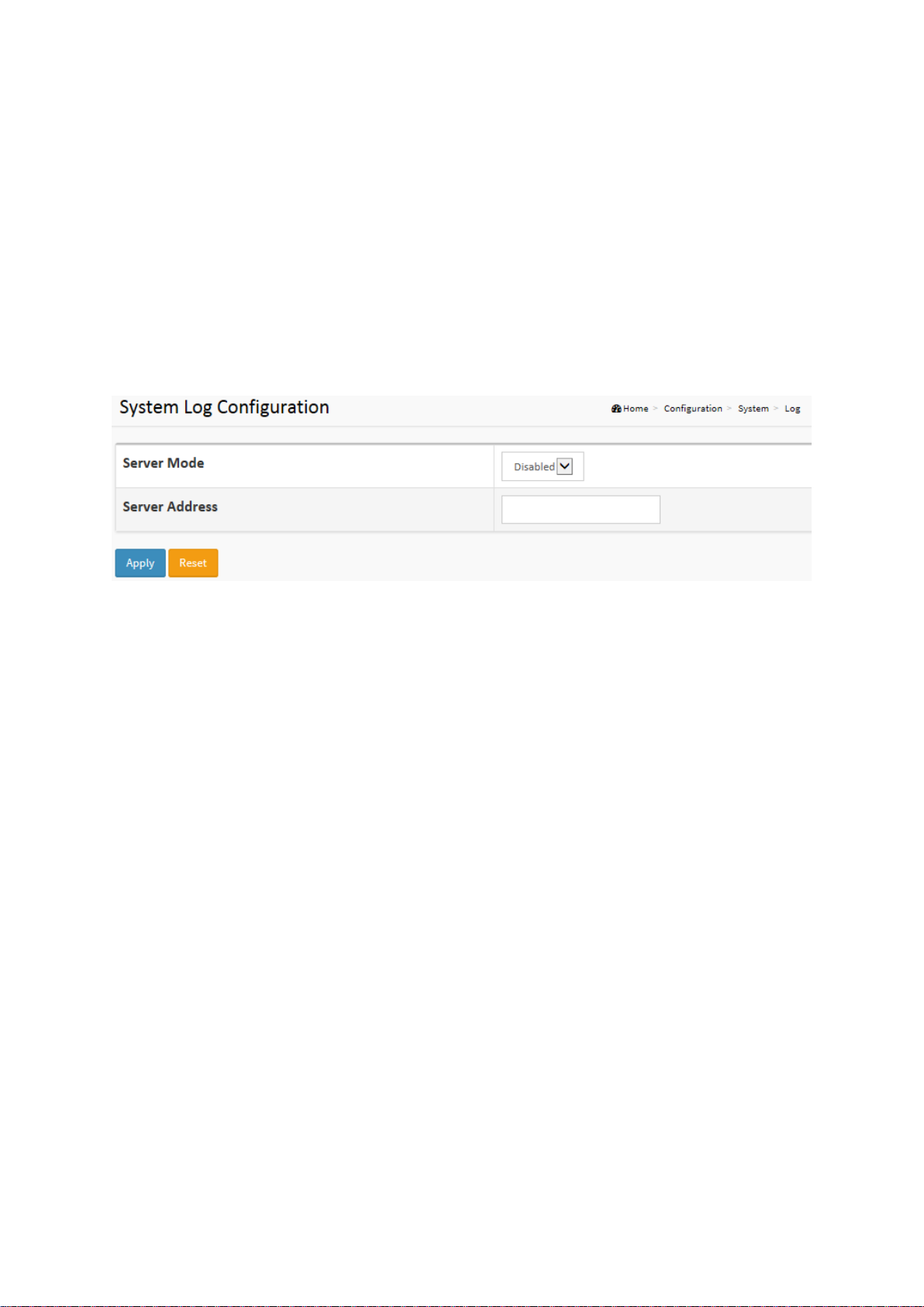
Figure2-1.5: The System Log Configuration
Parameter description:
Server Mode
Indicate the server mode operation. When the server mode operation is enabled, the syslog
message will send out to syslog server. The syslog protocol is based on UDP communication
and received on UDP port 514. The syslog server will not send acknowledgments back to
the sender since UDP is a connectionless protocol and it does not provide
acknowledgments. The syslog packet will always send out even if the syslog server does not
exist. Possible modes are:
Enabled: Enable server mode operation.
Disabled: Disable server mode operation.
Server Address
Indicates the IPv4 hosts address of syslog server. If the switch provide DNS feature, it also
can be a host name.
Buttons
These buttons are displayed on the Log page:
Apply – Click to save changes.
Reset - Click to undo any changes made locally and revert to previously saved values.
11
SG71070M
Revision A3
2-2 Ports Configuration
The section describes how to configure the Port detail parameters of the switch. Port configure
can be used to enable or disable a port, monitor the ports content, or status.
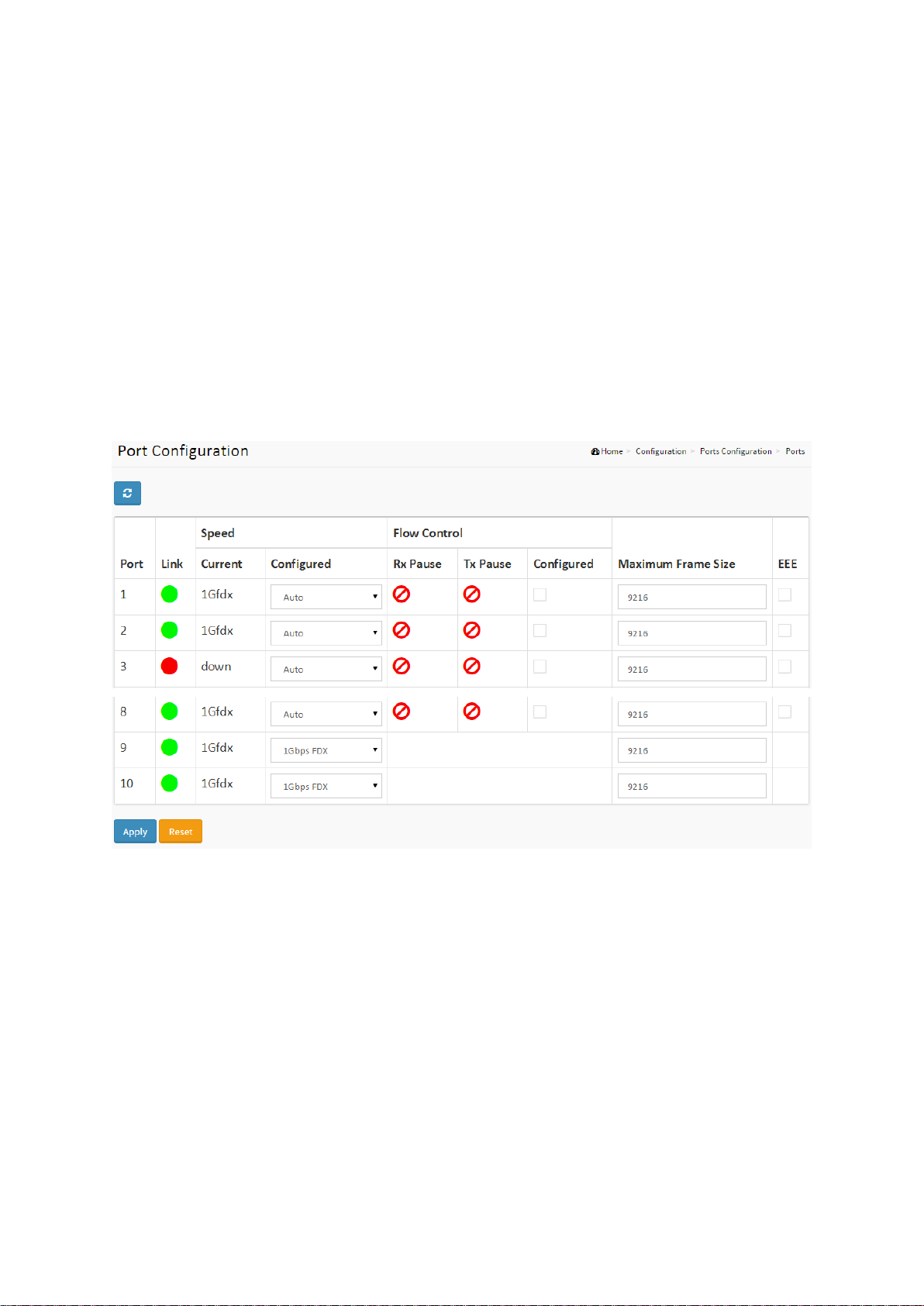
2-2.1 Ports
This page displays current port configurations.
Web Interface
To configure a port in the web interface:
1. Click Configuration, Ports Configuration, and Ports.
2. Specify the Speed Configured, Flow Control, Maximum Frame size, Excessive Collision
mode and Power Control.
3. Click Apply.
Figure 2-2.1: The Port Configuration
Parameter description:
Port
This is the logical port number for this row.
Link
The current link state is displayed graphically. Green indicates the link is up and red indicates
that it is down.
Current Link Speed
Provides the current link speed of the port.
Configured Link Speed
Use the menu to select the port’s speed and duplex mode. If you select Auto, the duplex
mode and speed will be set by the auto-negotiation process. The port’s maximum capability
(full duplex and 10 Gbps) will be advertised. Otherwise, your selection will determine the
port’s duplex mode and transmission rate. The factory default is Auto.
12
SG71070M
Revision A3

Maximum Frame Size
Enter the maximum frame size allowed for the switch port, including FCS.
EEE
Controls whether EEE is enabled for this switch port.
Buttons
Apply – Click to save changes.
Reset- Click to undo any changes made locally and revert to previously saved values.
Upper right icon (Refresh)
You can click them for refresh the Port link Status by manual
13
SG71070M
Revision A3
2-3 DHCP
The section describes how to configure the DHCP Snooping parameters of the switch. DHCP
Snooping can prevent attackers from adding their own DHCP servers to the network.
2-3.1 Snooping
DHCP Snooping is used to block intruders on the untrusted ports of the switch when it tries to
intervene by injecting a bogus DHCP reply packet to a legitimate conversation between the
DHCP client and server.
The section describes how to configure the DHCP Snooping parameters of the switch. The
DHCP Snooping can prevent attackers from adding their own DHCP servers to the network.
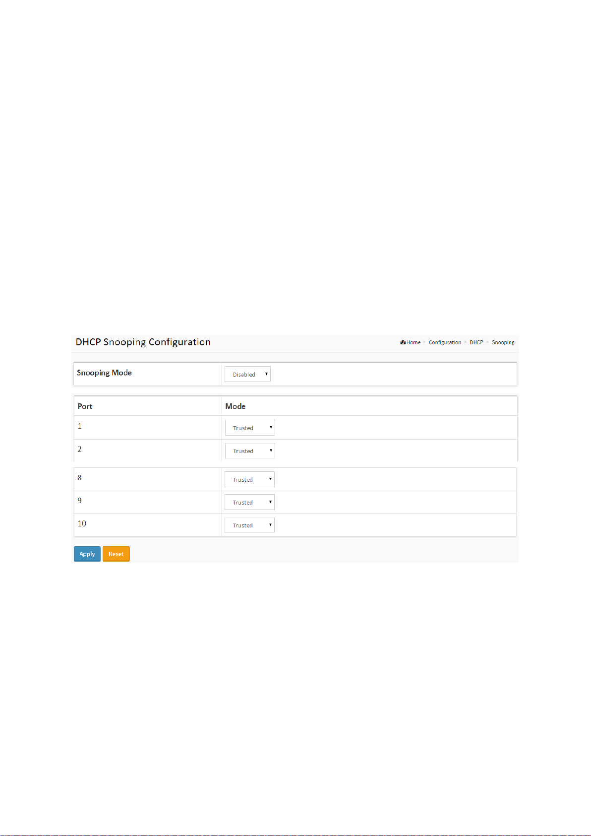
Web Interface
To configure DHCP Snooping Configuration in the web interface:
1. Click Configuration, DHCP, Snooping.
2. Select “Enabled” in the Mode of DHCP Snooping Configuration.
3. Select “Trusted” of the specific port in the Mode of Port Mode Configuration.
4. Click Apply.
Figure 2-3.1: The DHCP Snooping Configuration
Parameter description:
Snooping Mode
Indicates the DHCP snooping mode operation. Possible modes are:
Enabled: Enable DHCP snooping mode operation. When DHCP snooping mode operation is
enabled, the DHCP request messages will be forwarded to trusted ports and only allow reply
packets from trusted ports.
Disabled: Disable DHCP snooping mode operation.
Port Mode Configuration
Indicates the DHCP snooping port mode. Possible port modes are:
Trusted: Configures the port as trusted source of the DHCP messages.
Untrusted: Configures the port as untrusted source of the DHCP messages.
14
SG71070M
Revision A3
2-4 Security
This section shows you to configure the Port Security settings of the switch. You can use the
Port Security feature to restrict input to an interface by limiting and identifying MAC addresses.
2-4.1 Switch
2-4.1.1 Users
This page provides an overview of the current users. Currently the only way to login as another
user on the web server is to close and reopen the browser.
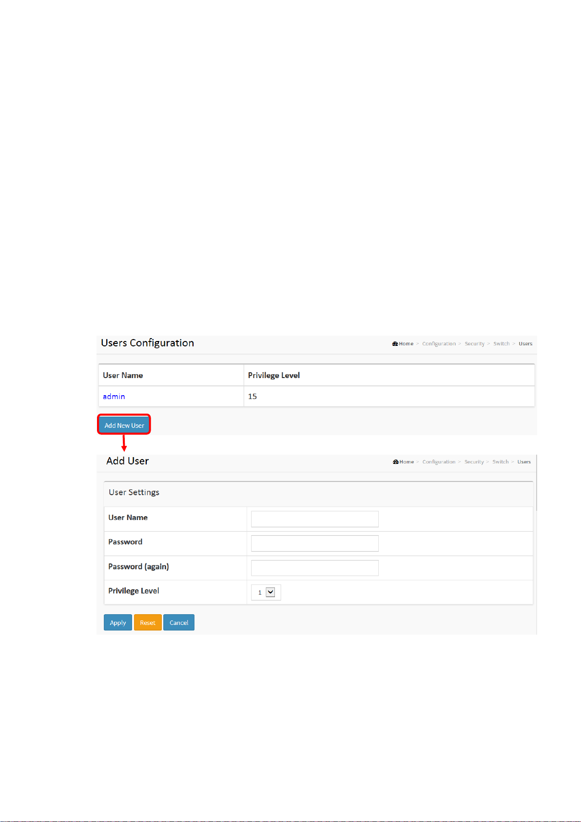
Web Interface
To configure User in the web interface:
1. Click Configuration, Security, Switch, Users.
2. Click Add new user.
3. Specify the User Name parameter.
4. Click Apply.
Figure 2-4.1.1: The Users configuration
Parameter description:
User Name
The name identifying the user. This is also a link to Add/Edit User.
Password
To type the password. The allowed string length is 0 to 255, and the allowed content is the
15
SG71070M
Revision A3

ASCII characters from 32 to 126.
Password (again)
To type the password again. You must type the same password again in the field.
Privilege Level
The privilege level of the user. The allowed range is 1 to 15. If the privilege level value is 15, it
can access all groups, i.e. that is granted the fully control of the device. But other’s value
need to refer to each group privilege level. User's privilege should be same or greater than
the group privilege level to have the access of that group. By default, most group’s privilege
level is 5 and has the read-only access, and privilege level 10 has the read-write access. The
system maintenance (software upload, factory defaults and etc.) need user privilege level 15.
Generally, the privilege level 15 can be used for an administrator account, privilege level 10
for a standard user account, and privilege level 5 for a guest account.
Buttons
Apply – Click to save changes.
Reset - Click to undo any changes made locally and revert to previously saved values.
Cancel - Click to undo any changes made locally and return to the Users.
Delete User - Delete the current user. This button is not available for new configurations
(Add new user)
16
SG71070M
Revision A3
2-4.2 Network
2-4.2.1 Access Control List
The section describes how to configure the Access Control List rules. An Access Control List
(ACL) is a sequential list of permit or deny conditions that apply to IP addresses, MAC
addresses, or other more specific criteria. This switch tests ingress packets against the
conditions in an ACL one by one. A packet will be accepted as soon as it matches a permit rule,
or dropped as soon as it matches a deny rule. If no rules match, the frame is accepted. Other
actions can also be invoked when a matching packet is found, including rate limiting, copying
matching packets to another port or to the system log, or shutting down a port.
This page shows the Access Control List (ACL), which is made up of the ACEs defined on this
switch. Each row describes the ACE that is defined. The maximum number of ACEs is 256 on
each switch. Click on the lowest plus sign to add a new ACE to the list. The reserved ACEs used
for internal protocol cannot be edited or deleted, the order sequence cannot be changed, and
the priority is highest.
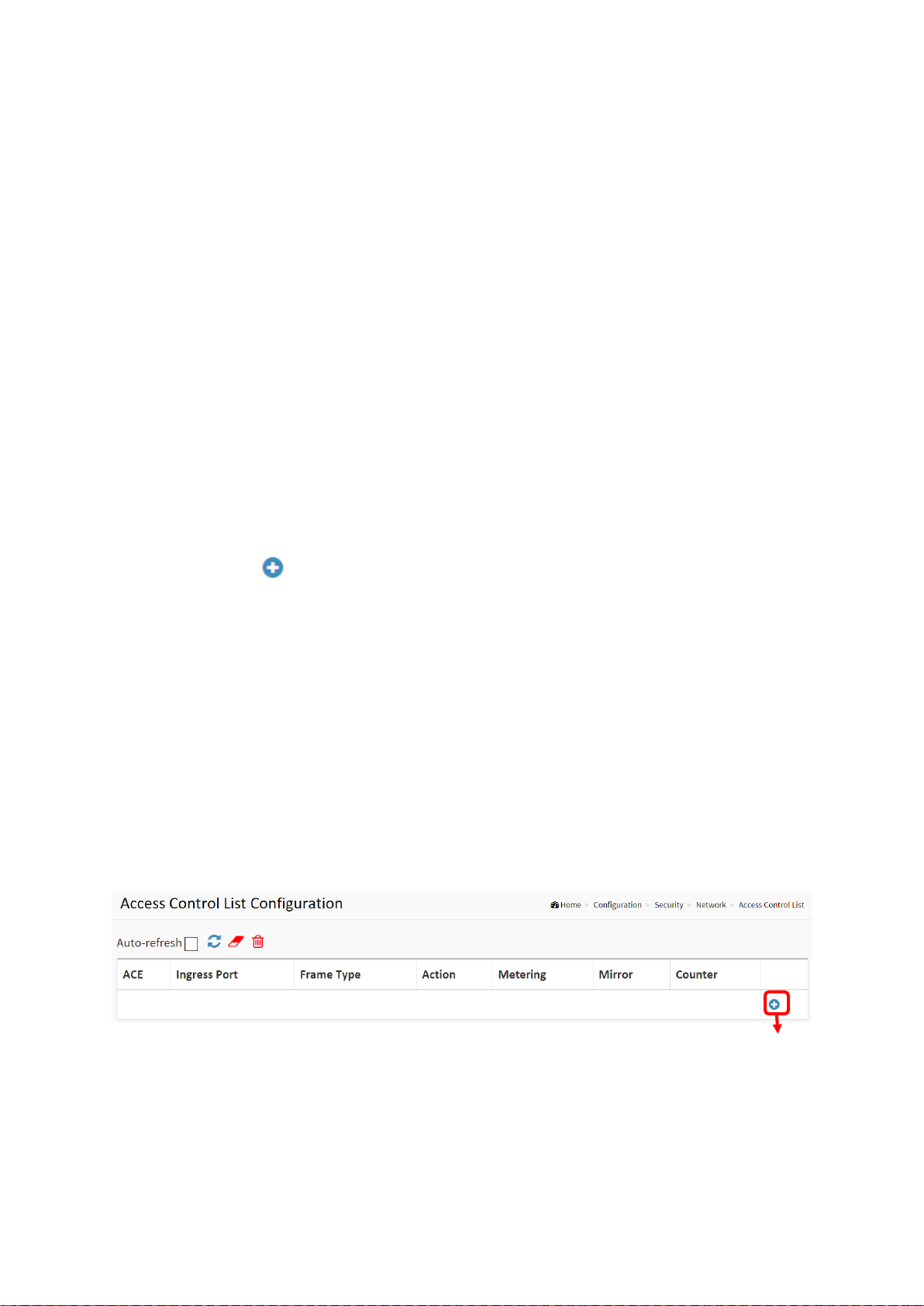
Web Interface
To configure Access Control List in the web interface:
1. Click Configuration, Security, Network and Access Control List.
2. Click the button to add a new ACL, or use the other ACL modification buttons to
specify the editing action (i.e., edit, delete, or moving the relative position of entry in the
list).
3. To specific the parameter of the ACE.
4. Click the save to save the setting.
5. If you want to cancel the setting then you need to click the reset button. It will revert to
previously saved values.
6. When editing an entry on the ACE Configuration page, note that the Items displayed
depend on various selections, such as Frame Type and IP Protocol Type. Specify the
relevant criteria to be matched for this rule, and set the actions to take when a rule is
matched (such as Rate Limiter, Port Copy, Logging, and Shutdown).
Figure 2-4.2.1: The Access Control List
17
SG71070M
Revision A3
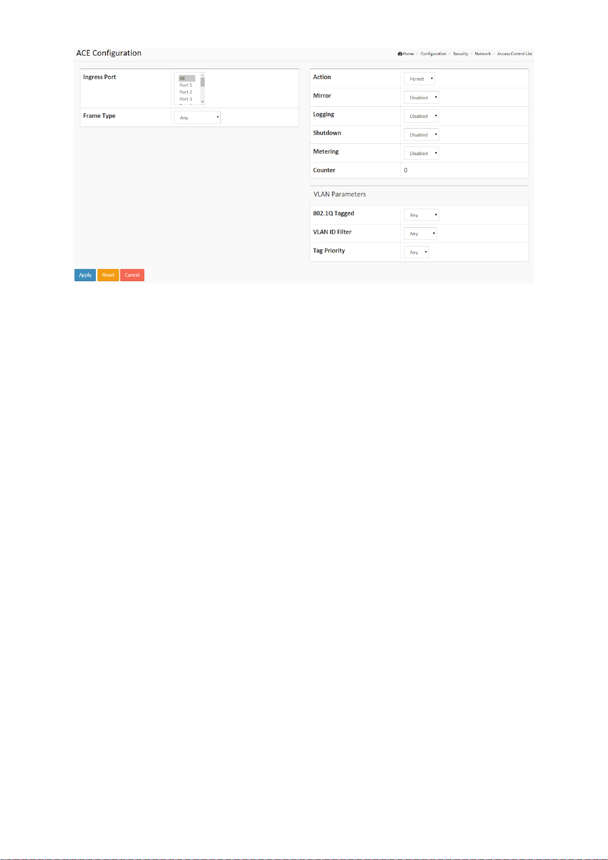
Parameter description:
Ingress Port
Indicates the ingress port of the ACE. Possible values are:
Any: The ACE will match any ingress port.
Policy: The ACE will match ingress ports with a specific policy.
Port: The ACE will match a specific ingress port.
Frame Type
Indicates the frame type of the ACE. Possible values are:
Any: The ACE will match any frame type.
EType: The ACE will match Ethernet Type frames. Note that an Ethernet Type based ACE will
not get matched by IP and ARP frames.
ARP: The ACE will match ARP/RARP frames.
IPv4: The ACE will match all IPv4 frames.
IPv4/ICMP: The ACE will match IPv4 frames with ICMP protocol.
IPv6: The ACE will match all IPv6 standard frames.
Action
Indicates the forwarding action of the ACE.
Permit: Frames matching the ACE may be forwarded and learned.
Deny: Frames matching the ACE are dropped.
Filter: Frames matching the ACE are filtered.
Metering
Indicates the rate limiter number of the ACE. The allowed range is 1 to 16. When Disabled is
displayed, the rate limiter operation is disabled.
Mirror
Specify the mirror operation of this port. The allowed values are:
18
SG71070M
Revision A3

Enabled: Frames received on the port are mirrored.
Disabled: Frames received on the port are not mirrored.
The default value is "Disabled".
Logging
Indicates the logging operation of the ACE. Possible values are:
Enabled: Frames matching the ACE are stored in the System Log.
Disabled: Frames matching the ACE are not logged.
Please note that the System Log memory size and logging rate is limited.
Shutdown
Indicates the port shut down operation of the ACE. Possible values are:
Enabled: If a frame matches the ACE, the ingress port will be disabled.
Disabled: Port shut down is disabled for the ACE.
Counter
The counter indicates the number of times the ACE was hit by a frame.
Modification Buttons
You can modify each ACE (Access Control Entry) in the table using the following buttons:
: Inserts a new ACE before the current row.
: Edits the ACE row.
: Deletes the ACE.
MAC Parameter
SMAC Filter
(Only displayed when the frame type is Ethernet Type or ARP.)
Specify the source MAC filter for this ACE.
Any: No SMAC filter is specified. (SMAC filter status is "don't-care".)
Specific: If you want to filter a specific source MAC address with this ACE, choose this value.
A field for entering an SMAC value appears.
SMAC Value
When "Specific" is selected for the SMAC filter, you can enter a specific source MAC address.
The legal format is "xx-xx-xx-xx-xx-xx" or "xx.xx.xx.xx.xx.xx" or "xxxxxxxxxxxx" (x is a
hexadecimal digit). A frame that hits this ACE matches this SMAC value.
DMAC Filter
Specify the destination MAC filter for this ACE.
Any: No DMAC filter is specified. (DMAC filter status is "don't-care".)
MC: Frame must be multicast.
BC: Frame must be broadcast.
UC: Frame must be unicast.
Specific: If you want to filter a specific destination MAC address with this ACE, choose this
value. A field for entering a DMAC value appears.
19
SG71070M
Revision A3

DMAC Value
When "Specific" is selected for the DMAC filter, you can enter a specific destination MAC
address. The legal format is "xx-xx-xx-xx-xx-xx" or "xx.xx.xx.xx.xx.xx" or "xxxxxxxxxxxx" (x is a
hexadecimal digit). A frame that hits this ACE matches this DMAC value.
Buttons
Apply – Click to save changes.
Reset- Click to undo any changes made locally and revert to previously saved values.
Auto-refresh
To evoke the auto-refresh to refresh the information automatically.
Upper right icon (Refresh, clear, Remove All)
You can click them to refresh the ACL configuration or clear them manually. Or remove all to
clean up all ACL configurations on the table.
20
SG71070M
Revision A3
2-4.2.2 IP Source Guard
The section describes how to configure the IP Source Guard detail parameters of the switch.
You could use the IP Source Guard configuration to enable or disable a port of the switch.
2-4.2.2.1 Configuration
This section describes how to configure IP Source Guard settings including:
Mode (Enabled and Disabled)
Maximum Dynamic Clients (0, 1, 2, Unlimited)
Web Interface
To configure an IP Source Guard Configuration in the web interface:
1. Select “Enabled” in the Mode of IP Source Guard Configuration.
2. Select “Enabled” of the specific port in the Mode of Port Mode Configuration.
3. Select Maximum Dynamic Clients (0, 1, 2, Unlimited) of the specific port in the Mode of
Port Mode Configuration.
4. Click Apply.
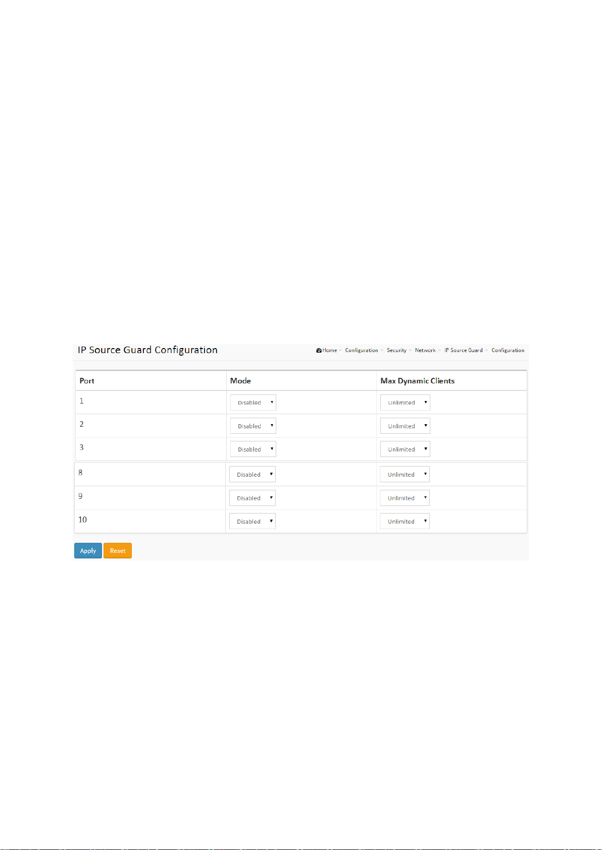
Figure 2-4.2.2.1: The IP Source Guard Configuration
Parameter description:
Port Mode Configuration
Specify IP Source Guard is enabled on which ports. Only when both Global Mode and Port
Mode on a given port are enabled, IP Source Guard is enabled on this given port.
Max Dynamic Clients
Specify the maximum number of dynamic clients that can be learned on given port. This
value can be 0, 1, 2 or unlimited. If the port mode is enabled and the value of max dynamic
client is equal to 0, it means only allow the IP packets forwarding that are matched in static
entries on the specific port.
21
SG71070M
Revision A3
2-4.2.2.2 Static Table
The section describes how to configure the Static IP Source Guard Table parameters of the
switch. You could use the Static IP Source Guard Table configuration to manage the entries.
Web Interface
To configure a Static IP Source Guard Table Configuration in the web interface:
1. Click “Add new entry”.
2. Specify the Port, VLAN ID, IP Address, and MAC address in the entry.
3. Click Apply.
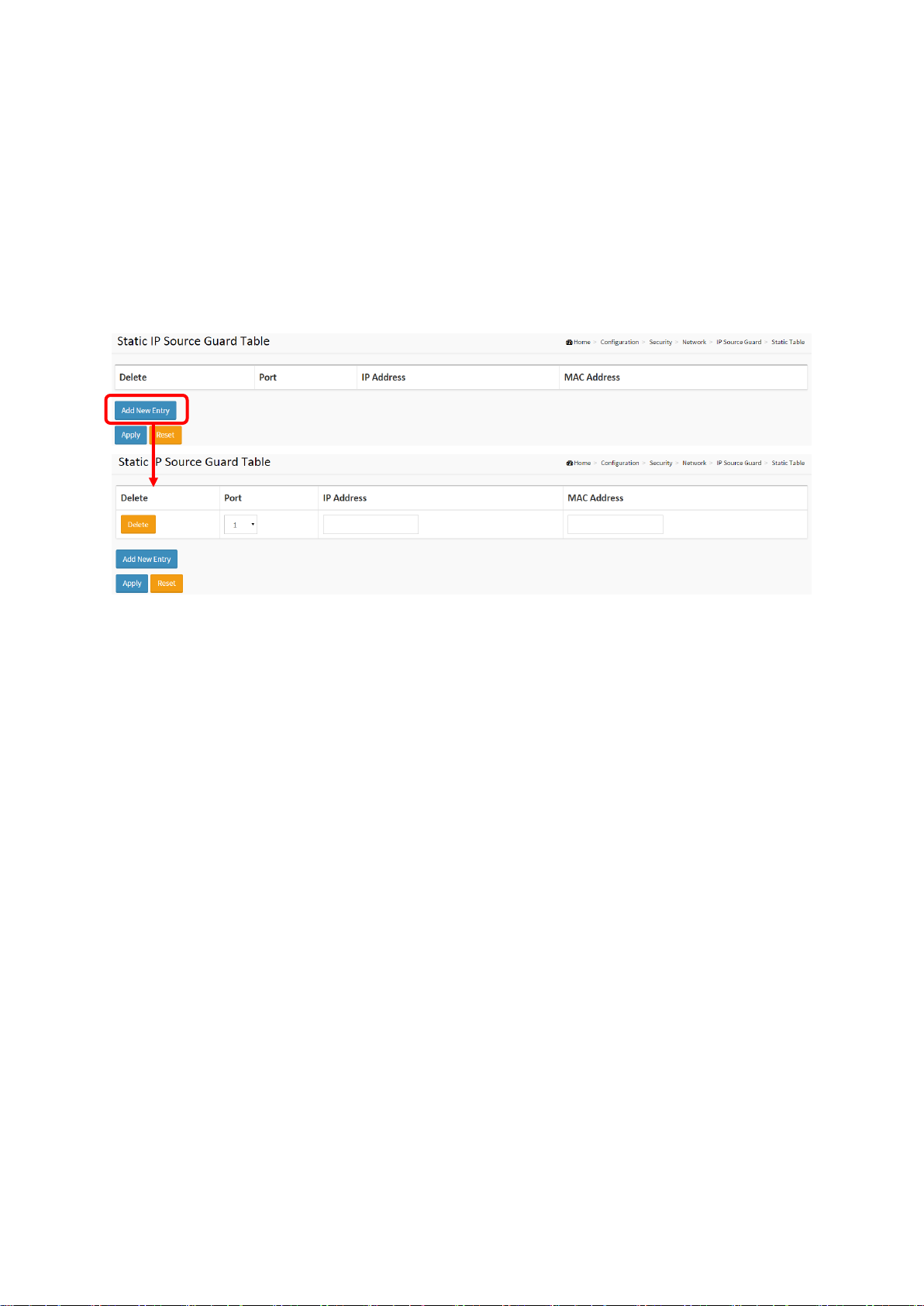
Figure 2-4.2.2.2: The Static IP Source Guard Table
Parameter description:
Delete
Check to delete the entry. It will be deleted during the next save.
Port
The logical port for the settings.
IP Address
Allowed Source IP address.
MAC address
Allowed Source MAC address.
Adding new entry
Click to add a new entry to the Static IP Source Guard table. Specify the Port, VLAN ID, IP
address, and IP Mask for the new entry. Click "Save".
Buttons
Apply – Click to save changes.
Reset- Click to undo any changes made locally and revert to previously saved values.
22
SG71070M
Revision A3
2-4.2.3 ARP Inspection
The section describes how to configure the ARP Inspection parameters of the switch. You could
use the ARP Inspection configuration to manage the ARP table.
2-4.2.3.1 Configuration
This section describes how to configure ARP Inspection settings including:
Mode (Enabled and Disabled).
Port (Enabled and Disabled).
Web Interface
To configure an ARP Inspection Configuration in the web interface:
1. Select “Enabled” in the Mode of ARP Inspection Configuration.
2. Select “Enabled” of the specific port in the Mode of Port Mode Configuration.
3. Click Apply.
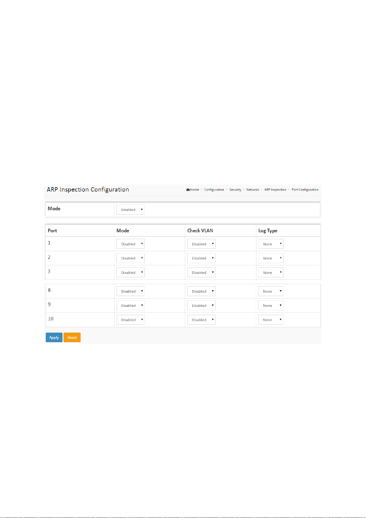
Figure 2-4.2.3.1: The ARP Inspection Configuration
Parameter description:
Mode of ARP Inspection Configuration
Enable the Global ARP Inspection or disable the Global ARP Inspection.
Port Mode Configuration
Specify ARP Inspection is enabled on which ports. Only when both Global Mode and Port
Mode on a given port are enabled, ARP Inspection is enabled on this given port. Possible
modes are:
Enabled: Enable ARP Inspection operation.
Disabled: Disable ARP Inspection operation.
If you want to inspect the VLAN configuration, you have to enable the setting of "Check
VLAN". The default setting of "Check VLAN" is disabled. When the setting of "Check VLAN"
is disabled, the log type of ARP Inspection will refer to the port setting. And the setting of
"Check VLAN" is enabled, the log type of ARP Inspection will refer to the VLAN setting.
Possible setting of "Check VLAN" are:
23
SG71070M
Revision A3

Enabled: Enable check VLAN operation.
Disabled: Disable check VLAN operation.
Only the Global Mode and Port Mode on a given port are enabled, and the setting of
"Check VLAN" is disabled, the log type of ARP Inspection will refer to the port setting. There
are four log types and possible types are:
None: Log nothing.
Deny: Log denied entries.
Permit: Log permitted entries.
ALL: Log all entries.
Buttons
Apply – Click to save changes.
Reset- Click to undo any changes made locally and revert to previously saved values.
24
SG71070M
Revision A3
 Loading...