

Page 1

VersiVision
FDVT110x / FDVR110x
1-CHANNEL DIGITALLY ENCODED VIDEO
AND
1-CHANNEL RETURN DATA
MULTIPLEXER
USER’S MANUAL
Revision B
© February 2006
VERSITRON, Inc.
83 Albe Drive / Suite C
Newark, DE 19702
www.versitron.com
FDVx110x
Page 2

PROPRIETARY DATA
All data in this manual is proprietary and may not be disclosed,
used or duplicated, for procurement or manufacturing purposes,
without prior written permission by VERSITRON.
WARRANTY
All VERSITRON products purchased after January 2001 carry a limited lifetime warranty
against defects in materials and workmanship for the lifetime of the product. Purchases made
prior to January 2001 are warranted for a period of one year from date of delivery.
VERSITRON reserves the right to repair or, at our option, replace parts which during normal
usage prove to be defective during the warranty period provided that:
1. You call VERSITRON at (302) 894-0699 or (800) 537-2296 and obtain a (RMA)
Return Authorization Number. Please reference your RMA number on the outside of the box in
which the item is returned.
2. Shipping charges are pre-paid.
No other warranty is expressed or implied and we are not liable for consequential damages.
For repairs outside of the warranty period, the same procedure must be followed.
www.versitron.com
FDVx110x
Page 3

Table of Contents
General Information ……………………………………………………………….. 3
Introduction ……………………………………………………………………. 3
Technical Specifications ………………………………………………………. 3
Installation Instructions …………………………………………………………… 6
Installation Procedure ……………………………………………….………… 6
Indicator LEDs ………………………………………………………………… 7
System Terminal Block Connections …………………………………………. 8
Wiring Diagrams ………………………………………………………………. 10
Troubleshooting …………………………………………………………………… 12
www.versitron.com
FDVx110x
Page 4

GENERAL INFORMATION
Introduction:
The VERSITRON VersiVision FDVT110x and FDVR110x Series video/data transmitter and
receiver support simultaneous transmission of one channels of 8-bit digitally encoded video and
one channel of return data over one multi-mode or single-mode optical fiber. The modules are
universally compatible with major camera systems and support RS-485 and RS-232 data
protocols. Plug and Play design ensures ease of installation and electronic and optical
adjustments are never required.
Model Number
Unit Type Model Number
One-channel Digitally Encoded Video/One-channel Data Transmitter FDVT110x
One-channel Digitally Encoded Video/One-channel Data Receiver FDVR110x
Technical Specifications:
VIDEO
Video Input 1 volt pk-pk (75 ohms)
Input/Output Channels 1
Bandwidth 5 Hz - 8 MHz
Bit Resolution 8-bit
Differential Gain < 2%
Differential Phase < 0.6°
Tilt < 1%
S/N Ratio 67dB (Weighed)
DATA
Data Interface RS-485/RS-232
Data Channel 1
Data Rate 100Kbps
Bit Error Rate 10-9
WAVELENGTH 850/1310nm Multimode
1310/1550nm Singlemode
OPTICAL EMITTER: Laser Diode
NUMBER OF FIBERS 1
www.versitron.com
FDVx110x
Page 5

Technical Specifications (cont.):
CONNECTORS
Optical SC, ST (FC Optional)
Video BNC
Data Shield RJ-45 Plug
GENERAL
Power Supply 5VDC @ 300mA
Size 4.57 x 5.31 x 1.42 Inches
Construction Aluminum
MTBF > 100,000 hours
Operating Temp -30° C to + 50° C
Storage Temp -40° C to + 85° C
Relative Humidity 0% to 95% (non-condensing)
INDICATOR
Blue Video Sync Present
Blue Data Sync Present
Orange Power On
www.versitron.com
FDVx110x
Page 6

OPTICAL POWER BUDGET
Optical transmission distance is limited to optical loss of the fiber and any additional loss
caused by connectors, splices, and patch panels.
CAUTION!
The transmitter unit contains a laser-emitting diode located in the optical connector.
This device emits invisible infrared electromagnetic radiation that can be harmful to
human eyes. The radiation from this optical connector, if viewed closely without any
protection, may cause instantaneous damage to the retina of the eye. Direct viewing
of this LED should be avoided at all times.
Singlemode 1310nm FDVT
Multimode 850nm FDVR
Transmitter Receiver Fiber Wavelength
Model Output Model Sensitivity
110x
Model Output Model Sensitivity
110x
-5 dBm
Receiver Transmitter Fiber Wavelength
-6 dBm
FDVR
110x
FDVT
110x
-26 dBm
-22 dBm
Optical
Power
Budget
21 dB
Optical
Power
Budget
16 dB
Max
Distance
30 Km
Max
Distance
3 Km
www.versitron.com
FDVx110x
Page 7

INSTALLATION INSTRUCTIONS
Installation Procedure
The VERSITRON VersiVision FDVT110x and FDVR110x video transmission systems
series are preset for immediate use. There are indicator LEDs on the units for monitoring the
real-time status of video, data and power. The following instructions describe the typical
installation procedure and the function of the LED indicators located on each unit.
1.
Connect the video source (camera) to the video input BNC connector on the transmitter
unit (FDVT110x) using coaxial cable.
2. Connect the video output BNC connector on the receiver unit (FDVR110x) to the video
monitor using coaxial cable.
3. Connect the fiber optic cable between the transmitter and receiver units.
4. Apply the power supply to both the transmitter and receiver units.
5. When the power is applied, the orange POWER LED will light, indicating the presence
of operating power. The blue VIDEO LED and the blue DATA LED will give an
indication as stated on the following pages.
6. The system should now be operational.
www.versitron.com
FDVx110x
Page 8
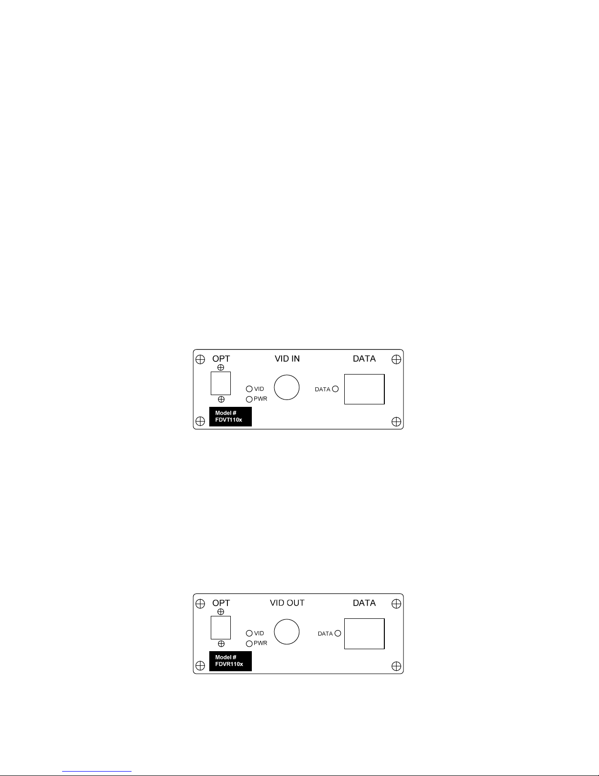
Indicator LEDs
The stand-alone units have integral LEDs that are used to monitor the state of the unit. There
are one video LED, one power LED and one data LED on each unit. The indicator LEDs
function as follows:
TRANSMITTER and RECEIVER:
Power:
ON: (Orange) Indicates that correct power has been applied
Transmitter:
Video: OFF: Indicates no video detected on input BNC connector
(No Video present on input BNC)
ON: (Blue) Indicates video detected on input BNC connector
(Video present on input BNC)
Data: OFF: Indicates no data detected on the transmit data cable
Blinking: (Blue) Indicates data transmitted at the rate of the operation data.
*Front Panel of FDVT110x (Transmitter)
Receiver:
Video: OFF: Indicates no video present on output BNC connector
(No Video present on output BNC)
ON: (Blue) Indicates video detected on output BNC connector
(Video present on input BNC)
Data: OFF: Indicates no data detected on the receive data cable
Blinking: (Blue) Indicates data received at the rate of the operation data.
www.versitron.com
*Front Panel of FDVR110x (Receiver)
FDVx110x
Page 9
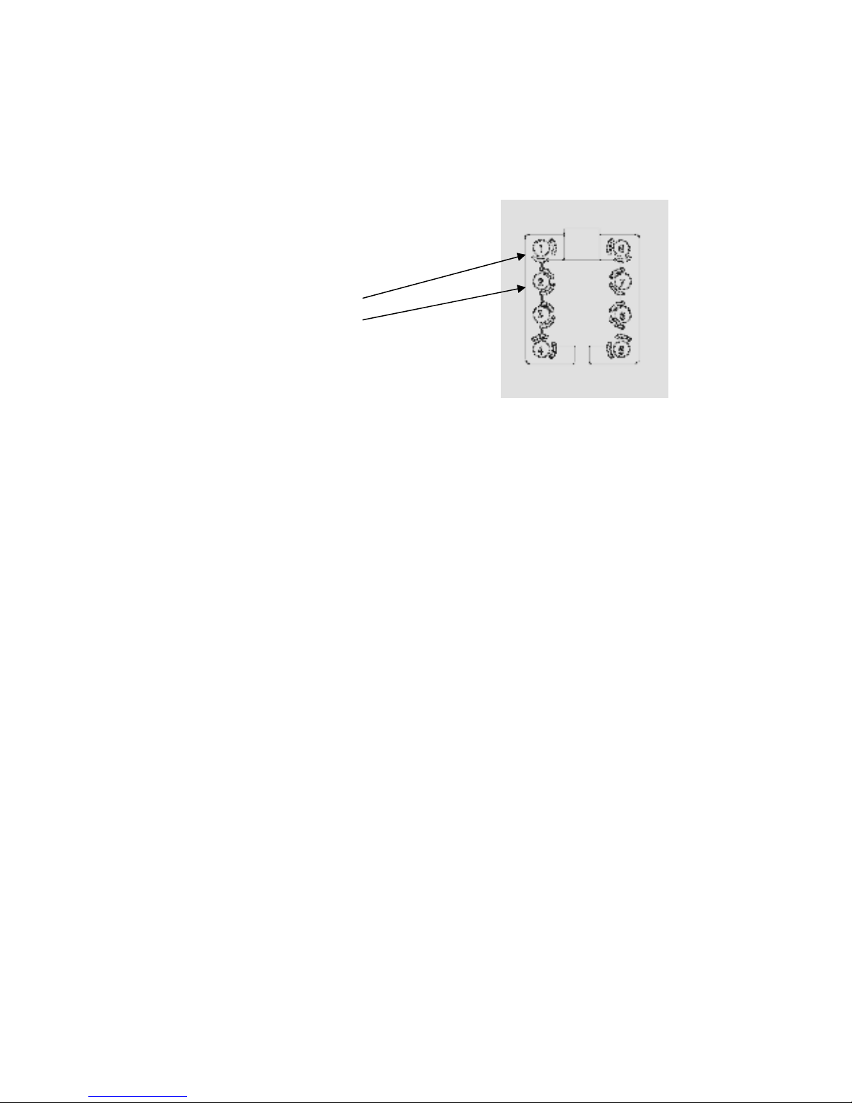
System Terminal Block Connections
The various input and output connections for the VERSITRON VersiVision FDVT110x and
FDVR110x video transmission systems series are as follows:
Video Input or Output: BNC Connectors
Data RS-485 Connection:
(Channel 1)
Terminal No.1——: RS-485 (+)
Terminal No.2——: RS-485 (-)
Camera Site
Connect Terminal No.1—— of the terminal block to RS-485 (+) of the controlled unit
(pan/tilt, dome), and connect Terminal No.2—— of the terminal block to RS-485 (-) of
the controlled unit (pan/tilt, dome).
Control Site
Similarly, connect Terminal No.1—— of the terminal block to RS-485 (+) of the
controlling unit (Keyboard Controller, Matrix, DVR), and connect Terminal No.2—— of
the terminal block to RS-485 (-) of the controlling unit (Keyboard Controller, Matrix, DVR).
*Terminal Block for Data Connection
www.versitron.com
FDVx110x
Page 10
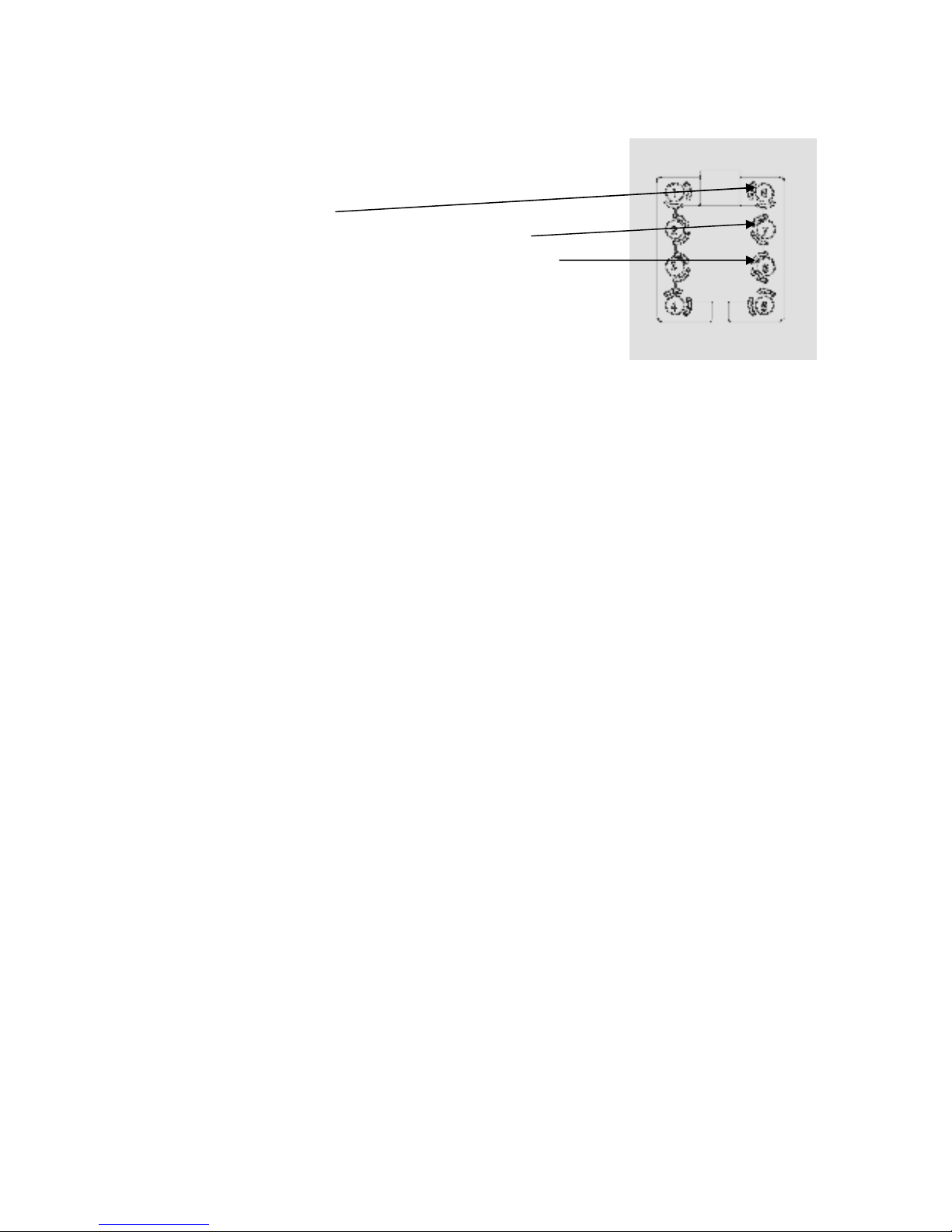
System Terminal Block Connections (cont.)
Data RS-232 Connection:
Terminal No.8: Ground
Terminal No.7: Signal being received in from fiber
Terminal No.6: Signal being transmitted out over fiber
*Terminal Block for Data Connection
Camera Site
Connect Terminal No. 7—— (232T) of the terminal block to the RS-232 (232R) port of
the controlled unit (pan/tilt, dome), and connect Terminal No. 8—— of the terminal block
to ground.
Control Site
Similarly, connect Terminal No. 6—— (232R) of the terminal block to the RS-232 (232R)
of the controlling unit (Keyboard Controller, Matrix, DVR), and connect Terminal No.
8—— of the terminal block to ground.
www.versitron.com
FDVx110x
Page 11
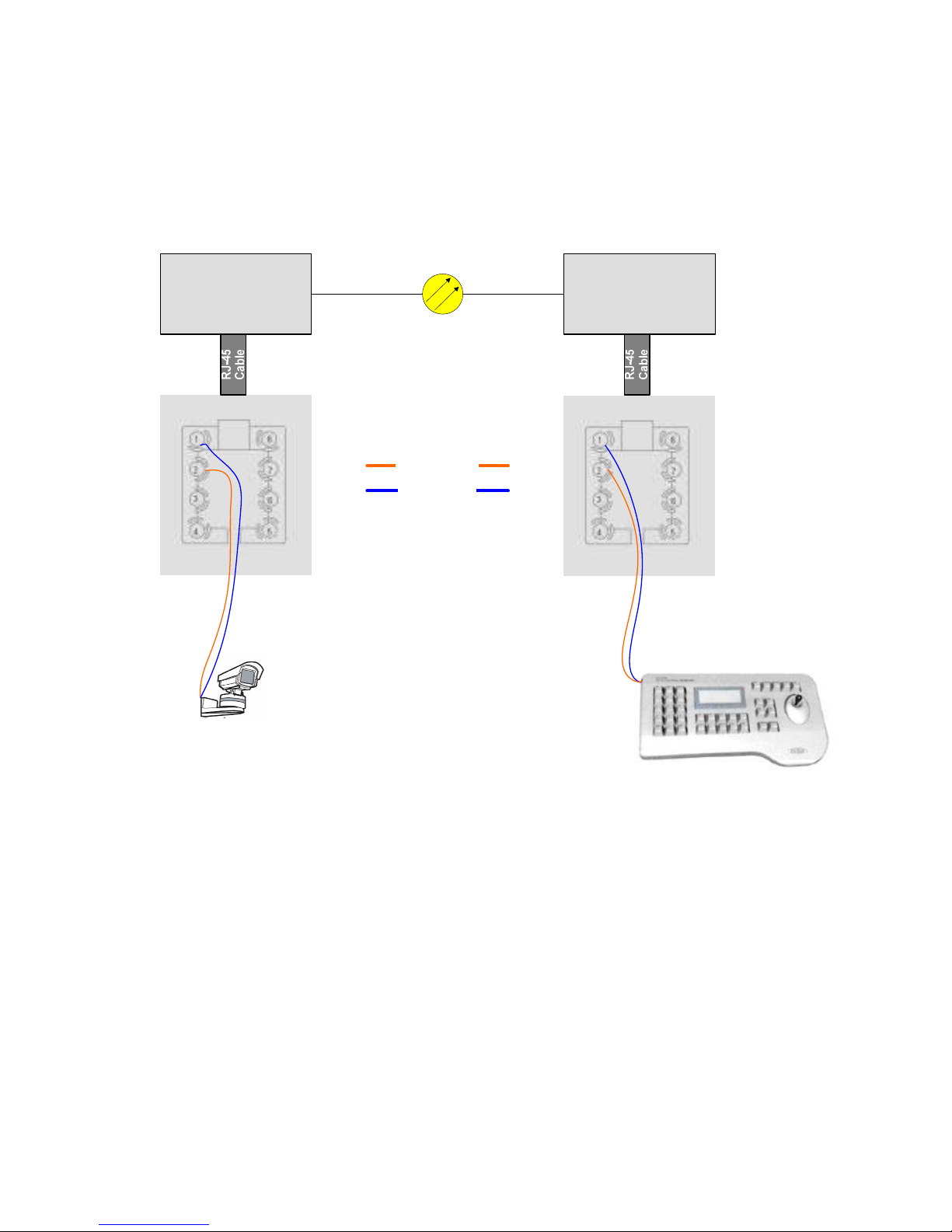
Wiring Diagrams
Typical wiring of RS-485 data control lines for PTZ cameras.
VersiVision
FDVT110x
Transmitter
Simplex
MM or SM Fiber
Channel 1 for
Return PTZ Control
RS-485 (+)
RS-485 (-)
VersiVision
FDVR110x
Receiver
PTZ Camera
PTZ Controller
NOTE: If your PTZ Controller has an RJ-45 jack for data input you can use the RJ-45
cable to connect the PTZ Controller directly to the FDVR110x, bypassing the terminal
block.
www.versitron.com
FDVx110x
Page 12
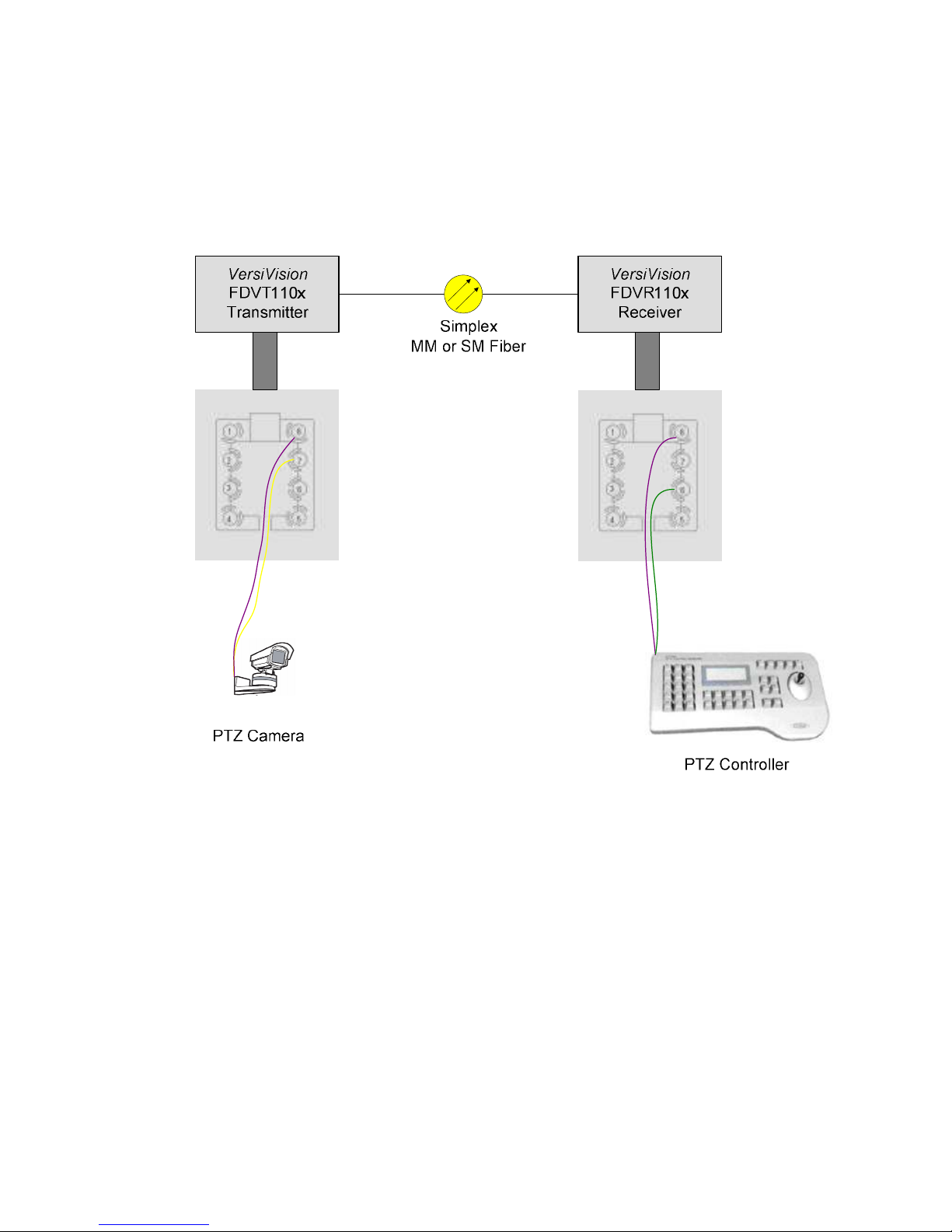
Wiring Diagrams (cont.)
Typical wiring of RS-232 data control lines for PTZ cameras.
RJ-45
Cable
RJ-45
Cable
NOTE: If your PTZ Controller has an RJ-45 jack for data input you can use the RJ-45
cable to connect the PTZ Controller directly to the FDVR110x, bypassing the terminal
block.
www.versitron.com
FDVx110x
Page 13

TROUBLESHOOTING
Optical Fiber
The VERSITRON VersiVision FDVT110x and FDVR110x video transmission systems
series is available for most applications using singlemode optical fibers. Please be certain
that the correct size and type of the fiber is being used for the particular transmitter/receiver
combination.
Also be certain that the attenuation and bandwidth of the fiber optic cable being used is
within the range of the system’s loss budget specifications.
General
Any dirt or dust may easily pollute or block the fiber from accepting or radiating light.
Therefore, please try to keep the optical connector clear and always use the dust caps
whenever the connector is exposed to air. It is suggested that the tip of the optical connecter
should be carefully cleaned with a lint-free cloth moistened with alcohol from time to time.
The status of any of the VIDEO LED should provide the first clue as to the origin of any
operational failure. If the VIDEO LED on the receiver unit is off, it usually means that the
fiber is broken or has too much attenuation.
Please also make sure that the transmitter and the receiver are not used in opposite positions.
If the system is still not working after examining the above possibilities, please contact our
Customer Service Department for further assistance
Data Link
Even when installed exactly as directed, it is possible that the data/audio function may fail to
operate properly. If this problem occurs, first please check the data cable, and then check
whether the data cable connector is firmly inserted into the RJ-45 port.
If the system is still not working after examining the above possibilities, please contact our
Customer Service Department for further assistance
www.versitron.com
FDVx110x
 Loading...