

Versitron SG72460M Installation Manual

SG72460M
Web Smart 10/100/1000
24- Port Ethernet Switch
with SFP support
Installation Guide
© February 2006
VERSITRON, Inc.
83 Albe Drive / Suite C
Newark, DE 19702
www.versitron.com
www.versitron.com 1 SG72460M

PROPRIETARY DATA
All data in this ma nual is proprietary and may not be disclosed,
used or duplicated, for procurement or manufacturing purposes,
without prior written permission by VERSITRON.
WARRANTY
All VERSITRON products are covered by a Lifetime Warranty against defects in materials and
workmanship. This coverage is applicable to the original purchaser and is not transferable.
We repair, or at our option, replace parts/products that, during normal usage and operation, are
proven to be defective during the time you own the products, provided that said products and
parts are still manufactured and/or available.
This warranty does not cover damage to products caused by misuse, mishandling, power surges,
accident, improper installation, neglect, alteration, improper maintenance, or other causes which
are not normal and customary application of the products and for which they were not intended.
No other warranty is expressed or implied, and VERSITRON is not liable for direct, indirect,
incidental or consequential damages or losses.
In the unlikely event a warranty issue should arise, simply contact us at 302-894-0699 or
1-800-537-2296 or via email to fiberlink@versitron.com and obtain a Return Material
Authorization (RMA) number. Reference this number on the outside of the shipping container
and return the unit (shipping charges prepaid) to us for diagnostic review and repair/replacement
as determined solely by VERSITRON. We pay the shipping charges to return the repaired unit or
a replacement unit to you.
Note: This warranty is effective for commercial products as of January 1, 2001.
www.versitron.com 2 SG72460M

The information contained in this document is subject to change without prior notice. Copyright
(C). All Rights Reserved.
TRADEMARKS
Ethernet is a registered trademark of Xerox Corp.
WARNING:
This equipment has been tested and found to comply with the limits for a Class A digital device,
pursuant to Part 15 of the FCC Rules. These limits are designed to provide reasonable protection
against harmful interference when the equipment is operat ed in a commercial environment. This
equipment generates, uses, and can radiate radio frequency energy and if not installed and used
in accordance with the instruction manual may cause harmful interference in which case the user
will be required to correct the interference at his/her own expense.
NOTICE:
(1) The changes or modifications not expressively approved by the party responsible for
compliance could void the user's authority to operate the equipment.
(2) Shielded interface cables and AC power cord, if any, must be used in order to comply with the
emission limits.
CISPR A COMPLIANCE:
This device complies with EMC directive of the European Community and meets or exceeds the
following technical standard.
EN 55022 - Limits and Methods of Measurement of Radio Interference Characteristics of
Information Technology Equipment. This device complies with CISPR Class A.
WARNING: This is a Class A product. In a domestic environment this product may cause radio
interference in which case the user may be required to take adequate measures.
CE NOTICE
Marking by the symbol indicates compliance of this equipment to the EMC directive of the
European Community. Such marking is indicative that this equipment meets or exceeds the
following technical standards:
EN 55022: Limits and Methods of Measurement of Radio Interference characteristics of
Information Technology Equipment.
EN 50082/1: Generic Immunity Standard -Part 1: Domestic Commercial and Light Industry.
EN 60555 -2: Disturbances in supply systems caused by household appliances and similar
electrical equipment - Part 2: Harmonics.
www.versitron.com 3 SG72460M

Table of Contents
1. Introduction ....................................................................................................................6
1.1 Features......................................................................................................................6
1.2 View of Web Smart 24-Port Gigabit Switch ................................................................7
1.3 Hardware Specifications ...........................................................................................8
1.4 Management Software Specifications........................................................................9
2. Installation.................................................................................................................... 10
2.1 Safety Cautions.........................................................................................................10
2.2 Desktop Mounting.....................................................................................................10
2.3 Applying Power.........................................................................................................10
2.4 SFP Transceiver Installation.....................................................................................10
2.5 Port and Cable..........................................................................................................11
2.6 Rack Mounting..........................................................................................................11
2.7 RESET Button...........................................................................................................11
2.8 Software Management .............................................................................................. 11
2.9 IP Address Settings and Changing Password.........................................................11
2.10 Initi al Switch Access and Configuration ................................................................12
3. Operation of Web-based Management ..........................................................................15
3.1 Web Management Home Overview .........................................................................16
3.2 Configuration.............................................................................................................17
3.2.1 System Configuration ............................................................................................18
3.2.2 Ports Configuration................................................................................................19
3.2.3 VLAN Mode Configuration.....................................................................................20
3.2.4 VLAN Group Configuration....................................................................................21
3.2.5 PVID Configuration................................................................................................23
3.2.6 Aggregation Configuration.....................................................................................24
3.2.7 Mirror Configuration...............................................................................................25
3.2.8 Quality of Service Configuration............................................................................26
3.2.8.1 VLAN Tag Configuration.....................................................................................27
3.2.8.2 IP ToS Classification...........................................................................................28
3.2.8.3 IP TCP/UDP Port Classification.........................................................................29
3.2.8.4 IP DiffServ Classification....................................................................................31
3.2.9 Bandwidth Management........................................................................................32
3.2.10 Trap Event Configuration.....................................................................................33
3.2.11 Max. Packet Length ............................................................................................. 34
3.3 Monitoring .................................................................................................................35
3.3.1 Statistics Overview ................................................................................................35
3.3.2 Detailed Statistics ................................................................................................36
3.4 Maintenance..............................................................................................................38
www.versitron.com 4 SG72460M

3.4.1 Status ...................................................................................................................38
3.4.2 Warm Restart.........................................................................................................40
3.4.3 Factory Default.......................................................................................................41
3.4.4 Software Update....................................................................................................42
3.4.5 Logout....................................................................................................................43
www.versitron.com 5 SG72460M
1. Introduction
Before you start installing the switch, verify that the package contains the following:
• Web Smart 24-Port 10/100/1000 Gigabit Ethernet Switch unit
• 19" rack mounting brackets
• This User Manual in CD-ROM
• AC Power Cord
1.1 Features
• Non-blocking store-and-forward Web-Smart switched.
• 24 10/100/1000Mbps Auto-negotiation Gigabit Ethernet copper ports
• 2 1000Mbps Gigabit Ethernet fiber ports (support dual media types, fiber and copper)
• 400KB on-chip frame buffer
• Jumbo frame support
• Diversified classification supports for QoS (even L4 support)
• 8K MAC ad dress and 4K VLAN support (IEEE802.1Q)
• Per-port bandwidth rate control and Broadcast Storm Control
• IEEE802.1Q VLAN support
• Full-duplex flow control (IEEE802.3x) and half -duplex backpressure
• Extensive front-panel diagnostic LEDs; System: Power, Copper Port1-24: LINK/ACT,
10/100/1000Mbps and SFP LINK/ACT
Management
• Supports concisely the status of port and easily port configuration
• Supports per port traffic monitoring counters
• Supports port mirror function
• Supports the static trunk function
• Supports 802.1Q VLAN
• Supports user management and limits one user to login
• Maximal packet length can be up to 9216 bytes for jumbo frame application
• Supports Broadcasting Suppression to avoid network suspended or crashed
• Supports to send the trap event while monitored events happened
• Supports default configuration , which can be restored to overwrite the current working
configuration on via Web UI and Reset button of the switch
• Supports on-line plug/unplug SFP modules
• Supports Quality of Se rvice (QoS) for real time applications based on the information taken
from Layer 2 to Layer 4, such as VoIP
• Built-in web-based management with convenient GUI for the user
www.versitron.com 6 SG72460M
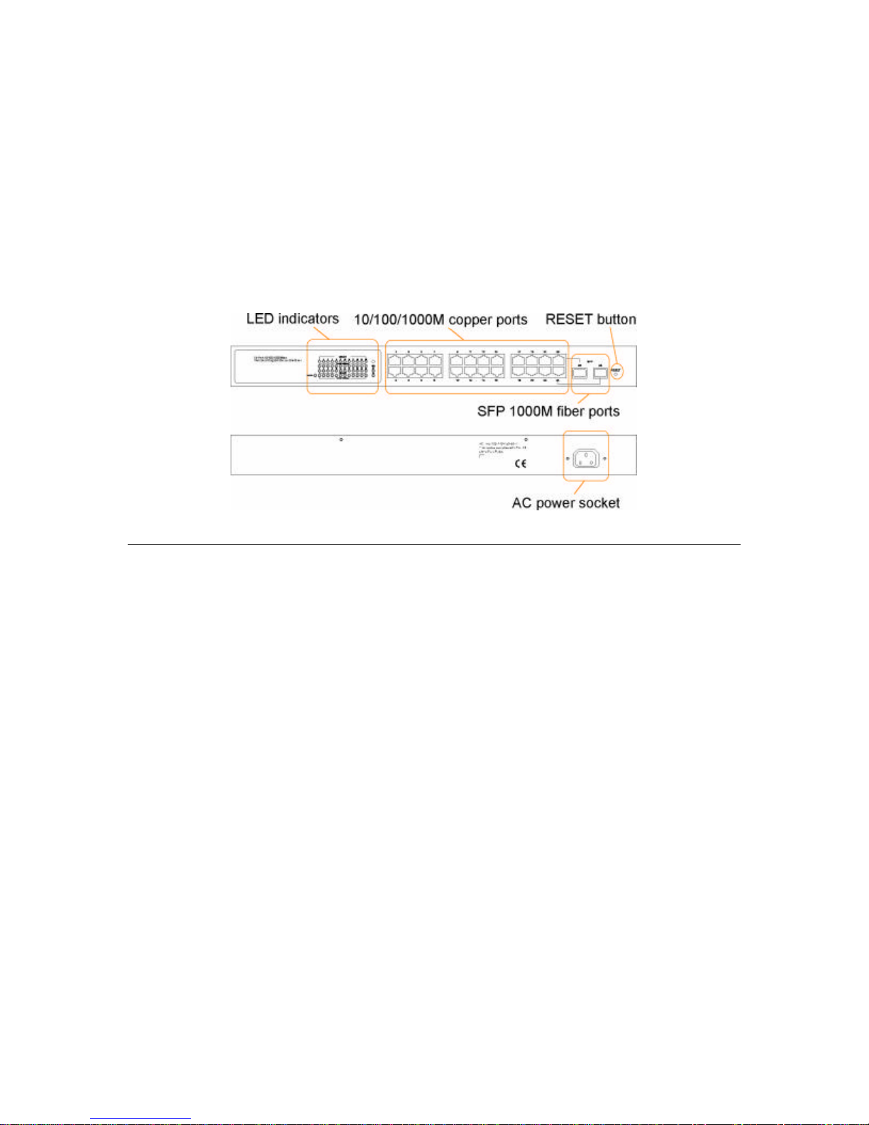
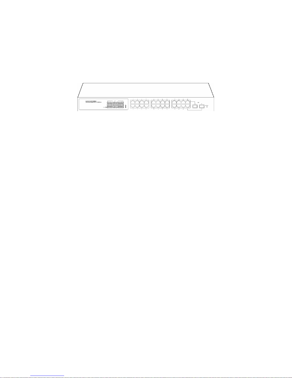
1.2 View of Web Smart 24-Port Gigabit Switch
The major user interface components on the front panel and rear panel are:
•LED indicators LED Display for system power status and port status
•10/100/1000M copper ports Gigabit copper ports (Port 1 - Port 24)
•1000M SFP fiber ports Gigabit fiber ports with SFP connectors (Port 23, Port 24)
•RESET button Button for reboot the switch or reset the switch to factory defaults
•AC power socket Power socket for AC power cord
LED Color Function
System POWER Green ON - when +5V DC power is on and good
Port 1~24 LINK/ACT Green ON - when connection with remote device is good
Blink - when any traffic is present
Off - when cable connection is not good
Port 1~24 10/100/1000Mbps G/E ON - green when 1000Mbps speed is active
ON - ember when 100Mbps speed is active
Off - when 10Mbps speed is active
Port 23, 24 SFP Green ON - when connection with remote device is good
Blink - when any traffic is present
Off - when cable connection is not good
www.versitron.com 7 SG72460M

1.3 Hardware Specifications
Standard Compliance: IEEE802.3/802.3ab / 802.3z / 802.3u / 802.3x
Network Interface:
Configuration Mode Connector Port
10/100/1000Mbps Gigabit Copper NWay RJ-45 1 - 24
1000Base-X Gigabit Fiber 1000 FDX SFP* 23, 24(Option)
*Port 23, 24 are RJ-45/SFP fiber dual media ports with auto detected function.
*Optional SFP modules support MMF, SMF LC or BiDi LC transceiver.
Transmission Mode: 10/100Mbps support full or half duplex, 1000Mbps support full duplex
only
Transmission Speed: 10/100/1000Mbps for Gigabit copper ports, 1000Mbps for Gigabit Fiber
ports
Full Forwarding Packet Rate: PPS (packets per second)
Forwarding Rate Speed
1,488,000pps 1000Mbps
148,800pps 100Mbps
14,880pps 10Mbps
MAC Address and Self-learning: 8K MAC address
VLAN Table: 4K VLAN table entries
Buffer Memory: Embedded 400 KB frame buffer
Flow Control:
IEEE802.3x compliant for full duplex
Backpressure flow control for half duplex
Cable and Maximum Length:
Gigabit copper Cat. 5 UTP cable Cat.5e recommended, up to 100m
Gigabit fiber 50/125, 60/125 MMF, 9/125 SMF, distance (depending on the SFP transceiver)
Diagnostic LED:
System LED: Power
Port 1 - 24 10/100/1000M : Speed status
Port 1 - 24 LINK/ACT : Link status and activities
Port 23, 24 SFP : SFP fiber link status
Power Requirement: Voltage 100 - 240 VAC, Frequency 50/60 Hz, Consumption 30W
Ambient Temperature: Operating 0 to 50oC, Humidity 5% to 90%
Dimensions: 44(H) x 442(W) x 209(D) mm
Approval: Comply with FCC Part 15 Class A & CE Mark Approval
www.versitron.com 8 SG72460M

1.4 Management Software Specifications
Interface: Web Http browsing
System configuration: IP address settings, system name, password, Auto-logout timer
Port configuration: Port operating mode, flow control
VLAN configuration
VLAN mode : Disable, Port-based, 802.1Q Tag-based, Metro (predefined Port-based)
VLAN groups : Up to 24 active groups, Group ID, description, VID, member ports
VID value range : 1 - 4094
Port VID range (PVID): 1 - 4094
Per Port Ingress Rules: Forward packets with VID=PVID, Drop untagged packets
Per Port Egress Rules: Port Tagging mode, Un-tagging specific VID packets
Link Aggregation (Trunking) Configuration
Trunks: up to 8 groups
Trunk port members: up to 8 ports
Mirroring Function
Sniffer mode : Ingress traffic of the source ports
Sniffer port: one port
Source ports: multiple ports are allowed
Quality of Service (QoS)
Priority class: High and low
Per port classification options: 802.1p, IP ToS, IP DSCP, IP TCP/UDP Port (L4 base)
Bandwidth Control
Per port basis control
Ingress Rate control: All traffic rate, Unicast rate, Broadcast/Multicast rate
Egress Rate control: All traffic rate
Trap Event Control
System events: Cold boot, Warm boot
Port events: Port link up, port link down, Invalid login, Tx error, Rx error
Event counters
Max. Packet Length Control:
Per port basis control
Option: 1518, 1532, 9216 (Jumbo frame support)
Statistics Monitoring: Per port basis control, Simplified port statistics, Detailed port statistics
Status Monitoring: All configuration current settings, All port link status
Maintenance:
Warm Restart (i.e. Reboot, Warm Boot)
Restore Factory default, Software update
Logout
www.versitron.com 9 SG72460M

2. Installation
2.1 Safety Cautions
To reduce the risk of bodily injury, electrical shock, fire, and damage to the equipment, observe
the following precautions.
• Do not service any product except as explained in your system documentation.
• Opening or removing covers may expose you to electrical shock.
• Only a trained service technician should service components inside these compartments.
• If any of the following conditions occur, unplug the product from the electrical outlet and
replace the part or contact your trained service provider:
- The power cable, extension cable, or plug is damaged.
- An object has fallen into the product.
- The product has bee n exposed to water.
- The product has been dropped or damaged.
- The product does not operate correctly when you follow the operating instructions.
• Do not push any objects into the openings of your system. Doing so can cause fire or electric
shock by shorting out interior components.
• Operate the product only from the type of external power source indicated on the electrical
ratings label. If you are not sure of the type of power source required, consult your service
provider or local power company.
2.2 Desktop Mounting
The switch can be mounted on a desktop or shelf. Make sure that there is proper heat dissipation
from and adequate ventilation around the device. Do not place heavy objects on the device.
2.3 Applying Power
One AC power cord, which meets the specification of your country of origin was supplied with
the switch unit. The switch supports wide range of AC power input specifications as follows:
Power Rating : 100 ~ 240VAC, 50/60Hz, 30W max.
Voltage Range : 90 ~ 264VAC
Frequency: 47 ~ 63 Hz
2.4 SFP Transceiver Installation
Verify the following Steps when installing an SFP transceiver into an empty SFP port:
1. Use the SFP transceivers qualified only by switch manufacturer.
2. The switch supports Hot-plug installation of the SFP transceiver even when the switch is on.
3. Make sure the transceiver is seated in the SFP port securely.
4. Install the fiber cable after the transceiver installation.
www.versitron.com 10 SG72460M

2.5 Port and Cable
Connection Cables
10/100M copper connection Cat.3, 4, 5, Cat.5 is recommended
1000M copper connection Cat. 5, 5e, Cat. 5e is recommended
1000M fiber connection MMF or SMF depending on the SFP transceiver used
2.6 Rack Mounting
Two 19-inch rack-mounting brackets are supplied with the switch for 19-inch rack mounting.
The steps to mount the switch onto a 19-inch rack are:
1. Turn the power to the switch off.
2. Install two brackets with supplied screws onto the switch.
2. Mount the switch onto 19-inch rack with rack screws securely.
3. Turn the power to the switch on.
2.7 RESET Button
The reset button is located on the front panel. The button provides the following functions:
Operation Function
Press the button more than 3 second Restore the switch back to factory default settings
Press the button less than 3 seconds Reboot the switch
2.8 Software Management
It will take about 30 seconds, after that, the switch will flash all the LED once and automatically
performs a self-test and is in the ready state. The switch features an http server, which can serve
the management requests coming from any web browser software over internet or intranet
network.
Web Browser
• Microsoft IE 6.0 above recommended, Netscape V7.1 above or FireFox V1.00 above
• Display resolution 1024x768.
Set IP Address for the switch unit
Before the switch can be managed from a web br owser software, make sure a unique IP address is
configured for the switch.
2.9 IP Address Settings and Changing Password
The switch is shipped with the following factory default settings:
• IP address o f the switch: 192.168.1.1
• Subnet Mask of the switch: 255.255.255.0
• Default Gateway of the switch: 192.168.1.254
• Password: admin
For security reason, it is recommended to change the default settings for the switch before
deploying it to your network:
To change IP address Use Web System Configuration Menu
To change password Use Web System Configuration Menu
www.versitron.com 11 SG72460M
2.10 Initial Switch Access and Configuration
Before the switch can be deployed into your network, you must first access the switch
from a local PC. To access the switch from your PC, follow the steps below:
(Note: The steps below are performed on the Windows XP operating system.)
1. Connect the switch to your PC by plugging a Cat5 or higher cable into the network
connection of your PC and one of the network connections on the front of the switch. Be
sure that the PC and switch are not connected to your local area network.
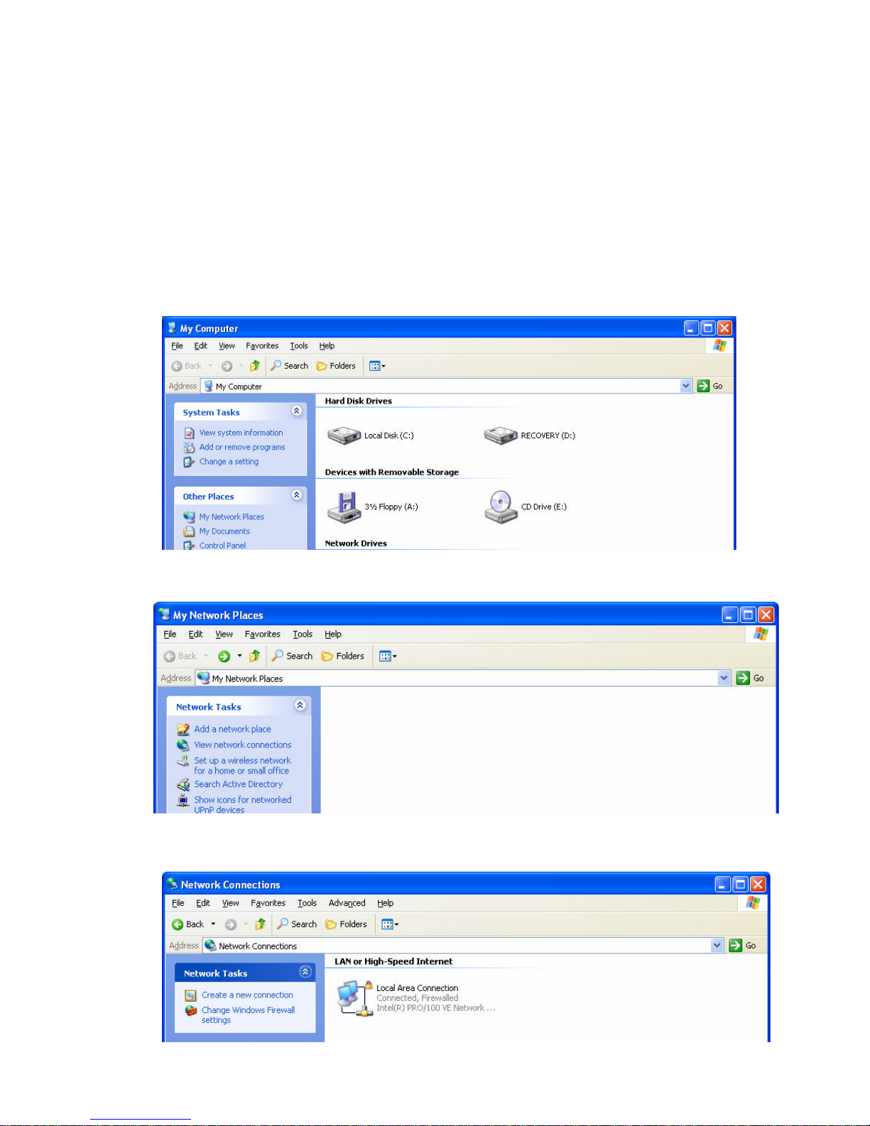
2. Click on the My Computer icon on the desk-top or Start Menu.
3. Click the My Network Places link under the Other Places heading.
4. Click on the View Network Connections link under the Network Tasks heading.
5. Double click on the Local Area Connections icon.
www.versitron.com 12 SG72460M
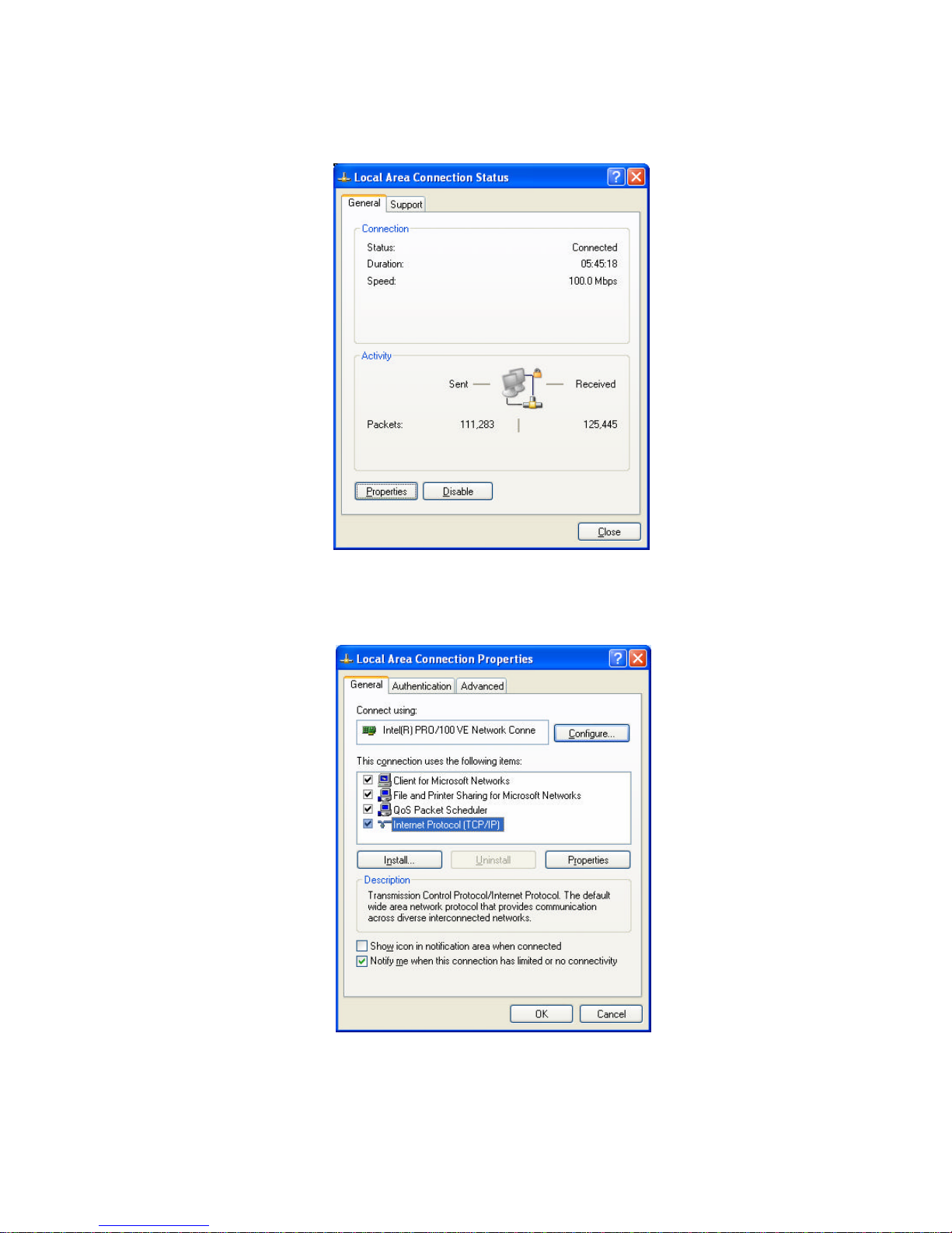
6. Click on the Properties button in the Local Area Connections Status window.
7. Double click on the Internet Protocol (TCP/IP) listing on the General tab in the Local Area
Connections Properties window.
www.versitron.com 13 SG72460M
 Loading...