

Versitron SG71660M User Manual

SG71660M
Web Smart 10/100/1000
16-Port Ethernet Switch
with SFP support
User’s Manual
© September 2007
VERSITRON, Inc.
83 Albe Drive / Suite C
Newark, DE 19702
www.versitron.com

PROPRIETARY DATA
All data in this manual is proprietary and may not be disclosed,
used or duplicated, for procurement or manufacturing purposes,
without prior written permission by VERSITRON.
WARRANTY
All VERSITRON products are covered by a Lifetime Warranty against defects in materials
and workmanship. This coverage is applicable to the original purchaser and is not transferable.
We repair, or at our option, replace parts/products that, during normal usage and operation, are proven
to be defective during the time you own the products, provided that said products and parts are still
manufactured and/or available.
This warranty does not cover damage to products caused by misuse, mishandling, power surges,
accident, improper installation, neglect, alteration, improper maintenance, or other causes which are
not normal and customary application of the products and for which they were not intended. No other
warranty is expressed or implied, and VERSITRON is not liable for direct, indirect, incidental or
consequential damages or losses.
In the unlikely event a warranty issue should arise, simply contact us at 302-894-0699 or 1-800-5372296 or via email to fiberlink@versitron.com and obtain a Return Material Authorization (RMA)
number. Reference this number on the outside of the shipping container and return the unit (shipping
charges prepaid) to us for diagnostic review and repair/replacement as determined solely by
VERSITRON. We pay the shipping charges to return the repaired unit or a replacement unit to you.
Note: This warranty is effective for commercial products as of January 1, 2001.

The information contained in this document is subject to change without prior notice.
Copyright ©. All Rights Reserved.
TRADEMARKS
Ethernet is a registered trademark of Xerox Corp.
WARNING:
This equipment has been tested and found to comply with the limits for a Class A digital device, pursuant to Part 15 of
the FCC Rules. These limits are designed to provide reasonable protection against harmful interference when the
equipment is operated in a commercial environment. This equipment generates, uses, and can radiate radio
frequency energy and if not installed and used in accordance with the instruction manual may cause harmful
interference in which case the user will be required to correct the interference at his/her own expense.
NOTICE:
(1) The changes or modifications not expressively approved by the party responsible for compliance could void the
user's authority to operate the equipment.
(2) Shielded interface cables and AC power cord, if any, must be used in order to comply with the emission
limits.
CISPR A COMPLIANCE:
This device complies with EMC directive of the European Community and meets or exceeds the following technical
standard.
EN 55022 - Limits and Methods of Measurement of Radio Interference Characteristics of Information
Technology Equipment. This device complies with CISPR Class A.
WARNING: This is a Class A product. In a domestic environment this product may cause radio interference in which
case the user may be required to take adequate measures.
CE NOTICE
Marking by the symbol
indicates compliance of this equipment to the EMC directive of the European
Community. Such marking is indicative that this equipment meets or exceeds the following technical standards:
EN 55022: Limits and Methods of Measurement of Radio Interference characteristics of Information
Technology Equipment.
EN 50082/1:Generic Immunity Standard -Part 1: Domestic Commercial and Light Industry.
EN 60555-2: Disturbances in supply systems caused by household appliances and similar electrical equipment Part 2: Harmonics.

Table of Contents
Caution ................................................................................................................................. iv
Electronic Emission Notices ................................................................................................. iv
1. Introduction .......................................................................................................................2
1-1. Overview of 16-Port GbE Web Smart Switch ................................................................2
1-2. Checklist.........................................................................................................................3
1-3. Features .........................................................................................................................3
1-4. View of 16-Port GbE Web Smart Switch........................................................................5
1-4-1. User Interfaces on the Front Panel (Button, LEDs and Plugs)...............................5
1-4-2. User Interfaces on the Rear Panel .........................................................................6
1-5. View of the Optional Modules ........................................................................................7
2. Installation .........................................................................................................................8
2-1. Starting 16-Port GbE Web Smart Switch Up..................................................................8
2-1-1. Hardware and Cable Installation ............................................................................8
2-1-2. Cabling Requirements ............................................................................................9
2-1-2-1. Cabling Requirements for TP Ports ..............................................................10
2-1-2-2. Cabling Requirements for 1000SX/LX SFP Module.....................................10
2-1-2-3. Switch Cascading in Topology ......................................................................11
2-1-3. Configuring the Management Agent of 16-Port GbE Web Smart Switch.............14
2-1-4. IP Address Assignment.........................................................................................16
2-2. Typical Applications ......................................................................................................21
3. Basic Concept and Management....................................................................................23
3-1. What’s the Ethernet......................................................................................................23
3-2. Media Access Control (MAC).......................................................................................26
3-3. Flow Control .................................................................................................................32
3-4. How does a switch work?.............................................................................................35
3-5. Virtual LAN ...................................................................................................................39
3-6. Link Aggregation ..........................................................................................................45
4. Operation of Web-based Management .............................................................................47
4-1. Web Management Home Overview .............................................................................48
4-2. Configuration................................................................................................................50
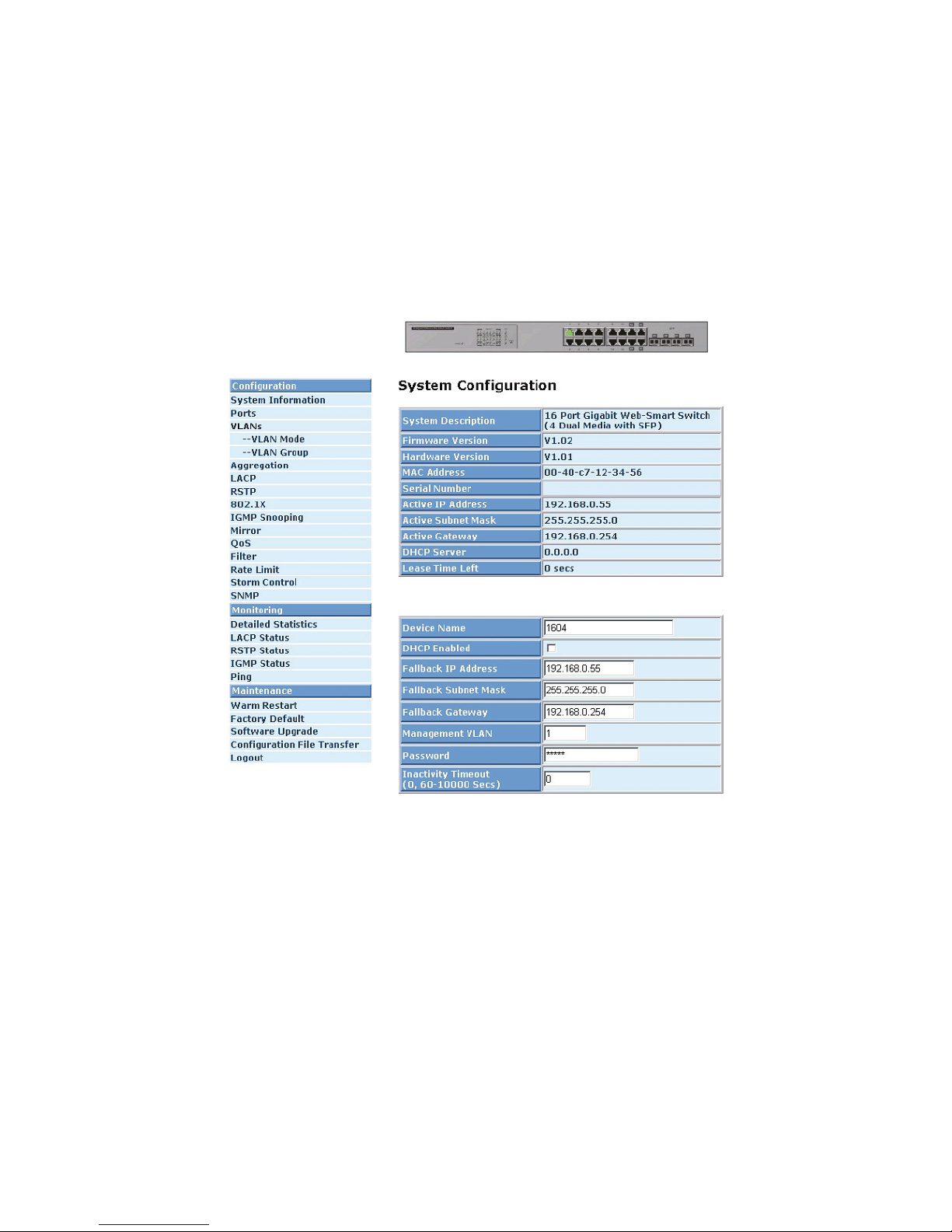
4-2-1. System Configuration ...........................................................................................51
4-2-2. Ports Configuration...............................................................................................54
4-2-3. VLAN Mode Configuration....................................................................................55
4-2-4. VLAN Group Configuration...................................................................................56
4-2-5. Aggregation...........................................................................................................59
4-2-6. LACP ....................................................................................................................59
4-2-7. RSTP ....................................................................................................................61
4-2-8. 802.1X ..................................................................................................................
4-2-9 IGMP Snooping .....................................................................................................69
4-2-10. Mirror Configuration............................................................................................70
4-2-11. QoS(Quality of Service) Configuration ...............................................................71
4-2-12 Filter.....................................................................................................................73
4-2-13 Rate Limit.............................................................................................................74
4-2-14 Storm Control.......................................................................................................75
4-2-15 SNMP ..................................................................................................................76
4-3. Monitoring ....................................................................................................................78
4-3-1. Statistics Overview ...............................................................................................78
4-3-2. Detailed Statistics .................................................................................................79
4-3-3. LACP Status .........................................................................................................82
4-3-4. RSTP Status .........................................................................................................83
4-3-5. IGMP Status..........................................................................................................83
4-3-6. Ping Status............................................................................................................84
4-4. Maintenance.................................................................................................................86
63
ii

4-4-1. Warm Restart........................................................................................................87
4-4-2. Factory Default .....................................................................................................88
4-4-3. Software Upgrade.................................................................................................89
4-4-4. Configuration File Transfer ...................................................................................90
4-4-5. Logout...................................................................................................................91
5. Maintenance .......................................................................................................................92
5-1. Resolving No Link Condition ........................................................................................92
5-2. Q&A..............................................................................................................................92
Appendix A Technical Specifications.......................................................................................93
iii

Caution
Circuit devices are sensitive to static electricity, which can damage their delicate electronics. Dry weather
conditions or walking across a carpeted floor may cause you to acquire a static electrical charge.
To protect your device, always:
• Touch the metal chassis of your computer to ground the static electrical charge before you pick up the circuit
device.
• Pick up the device by holding it on the left and right edges only.
Electronic Emission Notices
Federal Communications Commission (FCC) Statement
This equipment has been tested and found to comply with the limits for a class A computing device pursuant
to Subpart J of part 15 of FCC Rules, which are designed to provide reasonable protection against such
interference when operated in a commercial environment.
European Community (CE) Electromagnetic Compatibility Directive
This equipment has been tested and found to comply with the protection requirements of European
Emission Standard EN55022/EN60555-2 and the Generic European Immunity Standard EN50082-1.
EMC:
EN55022(1988)/CISPR-22(1985) class A
EN60555-2(1995) class A
EN60555-3
IEC1000-4-2(1995) 4K V CD, 8KV, AD
IEC1000-4-3(1995) 3V/m
IEC1000-4-4(1995) 1KV – (power line), 0.5KV – (signal line)
iv

About this user’s manual
This user’s manual provides instructions on how to install your Web Smart Switch.
This guide also covers management options and detailed explanation about hardware and software
functions.
Overview of this user’s manual
Chapter 1 “Introduction” describes the features of 16-Port Gigabit Web Smart Switch
Chapter 2 “Installation”
Chapter 3 “Operating Concept and Management”
Chapter 4 “Operation of Web-based Management”
Chapter 5 “Maintenance”

1. Introduction
1-1. Overview of 16-Port GbE Web Smart Switch
The 16-port Gigabit Web Smart Switch is a standard switch that meets all IEEE 802.3/u/x/z Gigabit,
Fast Ethernet specifications. The switch has 16 10/100/1000Mbps TP ports and 4 Gigabit TP/SFP
transceiver slots. It supports console, telnet, http and SNMP interfaces for switch management. The
network administrator can log on to the switch to monitor, configure and control each port’s activity. In
addition, the switch implements the QoS (Quality of Service), VLAN, and Trunking. It is suitable for office
applications.
In this switch, Port 13, 14, 15, 16 includes two types of media --- TP and SFP Fiber (LC, BiDi…);
this port supports 10/100/1000Mbps TP or 1000Mbps SFP Fiber with auto-detected function. 1000Mbps
SFP Fiber transceiver is used for high-speed connection expansion.
⎯ 1000Mbps LC, Multi-Mode, SFP Fiber transceiver
⎯ 1000Mbps LC, 10km, SFP Fiber transceiver
⎯ 1000Mbps LC, 30km, SFP Fiber transceiver
⎯ 1000Mbps LC, 50km, SFP Fiber transceiver
⎯ 1000Mbps BiDi, 20km, 1550nm SFP Fiber WDM transceiver
1000Mbps BiDi, 20km, 1310nm SFP Fiber WDM transceiver
10/100/1000Mbps TP is a standard Ethernet port that meets all IEEE 802.3/u/x/z Gigabit, Fast
Ethernet specifications. 1000Mbps SFP Fiber transceiver is a Gigabit Ethernet port that fully complies
with all IEEE 802.3z and 1000Base-SX/LX standards.
1000Mbps Single Fiber WDM (BiDi) transceiver is designed with an optic Wavelength Division
Multiplexing (WDM) technology that transports bi-directional full duplex signals over a single fiber
simultaneously.
•
Key Features in the Device
QoS:
The
switch offers a powerful QoS function. This function supports 802.1p VLAN tag priority and
DSCP on Layer 3 of network framework.
VLAN:
Supports Port-based VLAN, IEEE802.1Q Tag VLAN, 24 active VLANs, and VLAN ID 1~4094.
Port Trunking:
Allows one or more links to be aggregated together to form a Link Aggregation Group by the
static setting.
2

1-2. Checklist
Before you start installing the switch, verify that the package contains the following:
⎯ A 12-Port GbE Web Smart Switch
⎯ Modules (optional)
⎯ Mounting Accessory (for 19” Rack Shelf)
⎯ This User's Manual in CD-ROM
⎯ AC Power Cord
Please notify your sales representative immediately if any of the aforementioned items is missing or
damaged.
1-3. Features
The 16-Port GbE Web Smart Switch, a standalone off-the-shelf switch, provides the
comprehensive features listed below for users to perform system network administration and efficiently
and securely serve your network.
•
Hardware
• 12 10/100/1000Mbps Auto-negotiation Gigabit Ethernet TP ports
• 4 10/100/1000Mbps TP or 1000Mbps SFP Fiber dual media auto sense
• 400KB on-chip frame buffer
• Jumbo frame support
• Programmable classifier for QoS (Layer 2/Layer 3)
• 8K MAC address and support VLAN ID (1~4094)
• Per-port shaping, policing, and Broadcast Storm Control
• IEEE802.1Q-in-Q nested VLAN support
• Full-duplex flow control (IEEE802.3x) and half-duplex backpressure
• Extensive front-panel diagnostic LEDs; System: Power, TP Port1-12: LINK/ACT,
10/100/1000Mbps, SFP Port 13, 14, 15, 16: SFP(LINK/ACT)
• Management
• Supports concisely the status of port and easily port configuration
• Supports per port traffic monitoring counters
• Supports a snapshot of the system Information when you login
• Supports port mirror function
• Supports the static trunk function
3

• Supports 802.1Q VLAN
• Supports user management and limits one user to login
• Maximal packet length can be up to 9600 bytes for jumbo frame application
• Supports Broadcasting Suppression to avoid network suspended or crashed
• Supports to send the trap event while monitored events happened
• Supports default configuration which can be restored to overwrite the current
configuration which is working on via Web UI and Reset button of the switch
• Supports on-line plug/unplug SFP modules
• Supports Quality of Service (QoS) for real time applications based on the
information taken from Layer 2 to Layer 3.
• Built-in web-based management instead of using CLI interface, providing a more
convenient GUI for the user
4
1-4. View of 16-Port GbE Web Smart Switch
Fig. 1-1 Full View of 16-PORT GbE Web Smart Switch
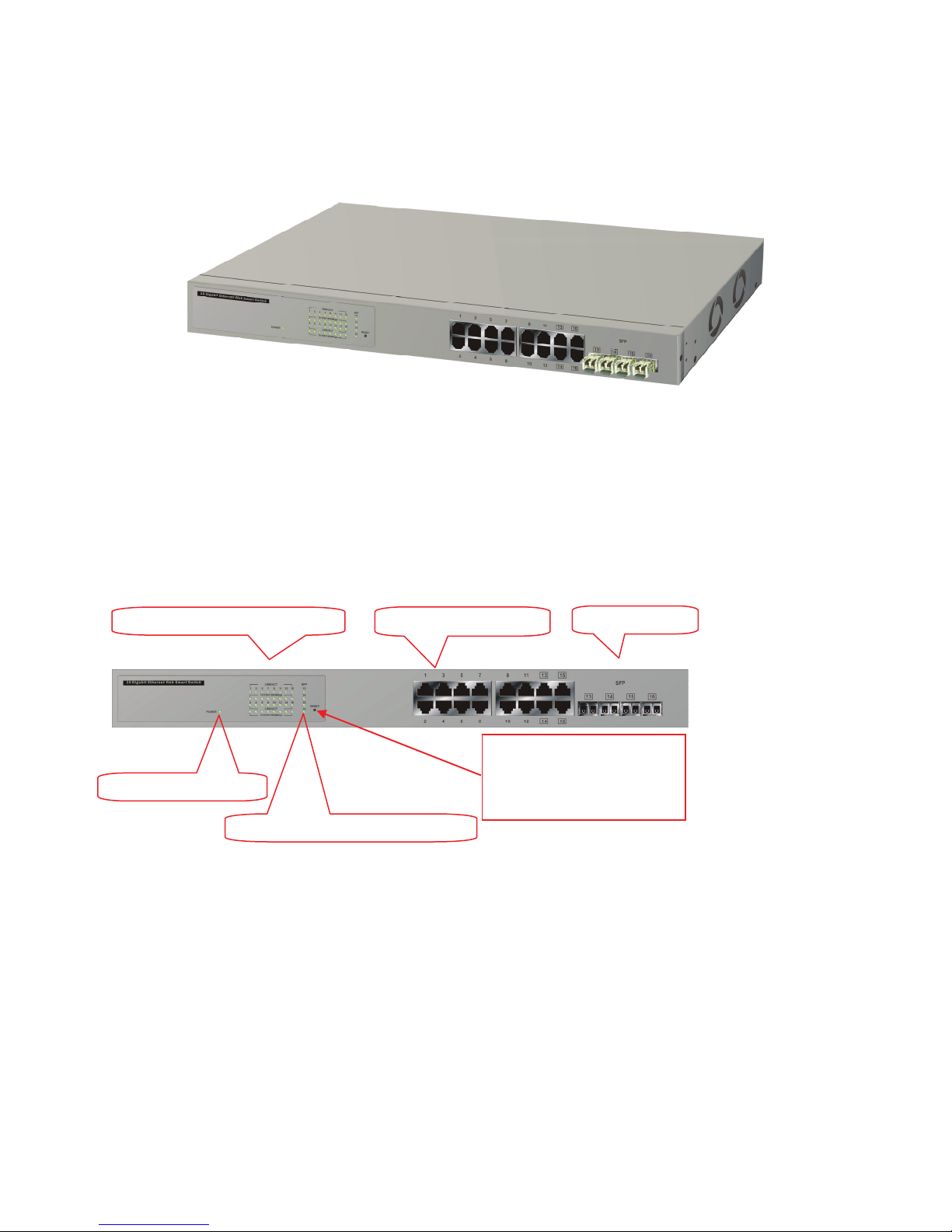
1-4-1. User Interfaces on the Front Panel (Button, LEDs and Plugs)
There are 12 TP Gigabit Ethernet ports and 4 SFP fiber ports for optional removable modules on
the front panel of the switch. LED display area, located on the left side of the panel, contains a Power
LED, which indicates the power status and 16 ports working status of the switch.
TP Port Status Indication LEDs
Power Indication LED
Fiber Port Status Indication LEDs
Fig. 1-2 Front View of 16-Port GbE Web Smart Switch
Gigabit Ethernet Port
RESET Button:
RESET button is used to
restore the system default
setting.
SFP Fiber Port
5
• LED Indicators
LED Color Function
System LED
POWER Green
10/100/1000Ethernet TP Port 1 to 12 LED
LINK/ACT Green
10/100/1000Mbps
1000SX/LX Gigabit Fiber Port 13, 14, 15, 16 LED
SFP(LINK/ACT) Green
Green/
Amber
Lit when +3.3V power is coming up
Lit when connection with remote device is good
Blinks when any traffic is present
Lit Green when TP link on 1000Mbps speed
Lit Amber when TP link on 100Mbps speed
Off when 10Mbps or no link occur
Blinks when any traffic is present
Lit when SFP connection with remote device is
good
Blinks when any traffic is present
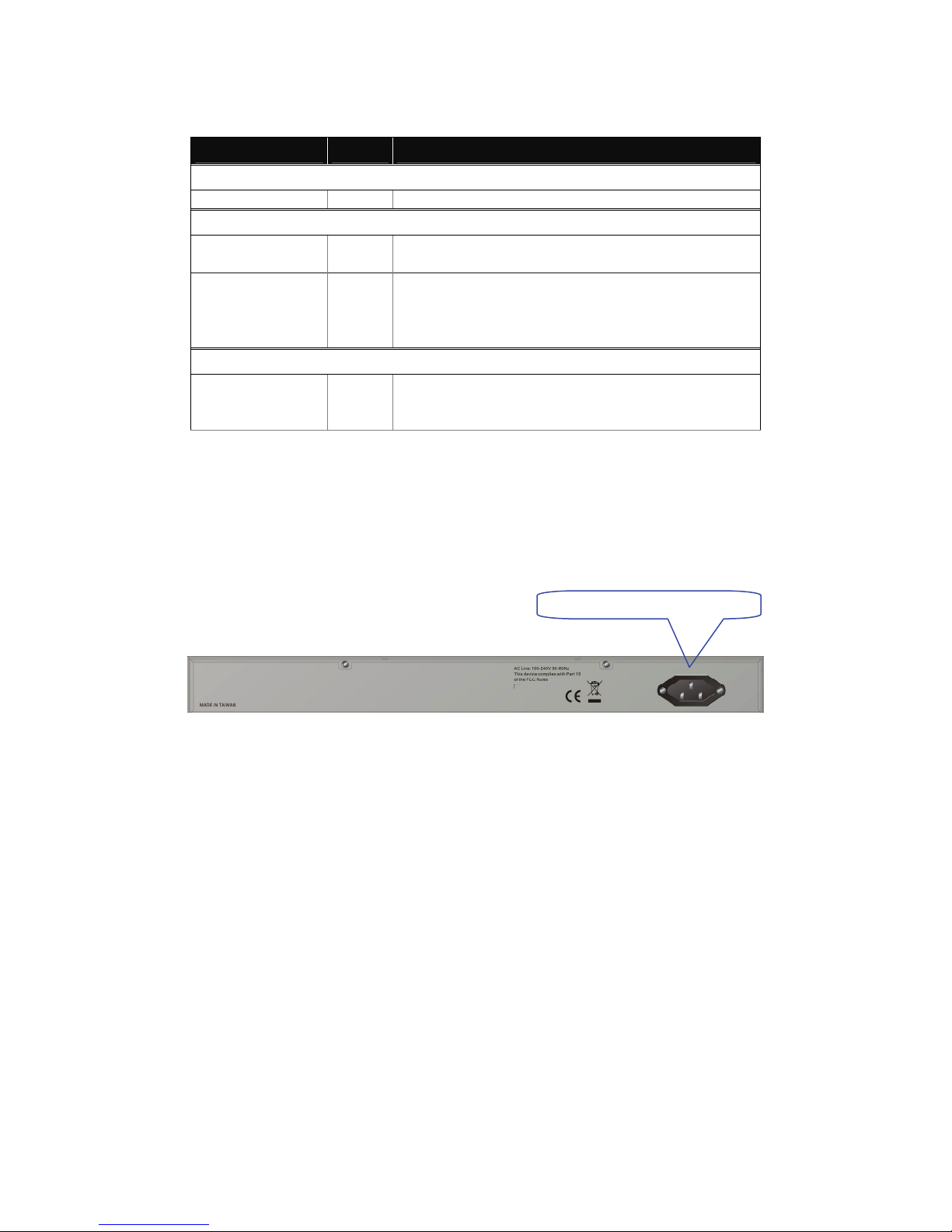
1-4-2. User Interfaces on the Rear Panel
Table1-1
AC Line 100-240V 50/60 Hz
Fig. 1-3 Rear View of 16-Port GbE Web Smart Switch
6
1-5. View of the Optional Modules
In the switch, Ports 13~16 include two types of media --- TP and SFP Fiber (LC, BiDi…); this port
supports 10/100/1000Mbps TP or 1000Mbps SFP Fiber with auto-detected function. 1000Mbps SFP Fiber
transceivers are used for high-speed connection expansion; nine optional SFP types provided for the
switch are listed below:
⎯ 1000Mbps LC, MM, SFP Fiber transceiver
⎯ 1000Mbps LC, SM 10km, SFP Fiber transceiver
⎯ 1000Mbps LC, SM 30km, SFP Fiber transceiver
⎯ 1000Mbps LC, SM 50km, SFP Fiber transceiver
⎯ 1000Mbps LC, SM 70km, SFP Fiber transceiver
⎯ 1000Mbps LC, SM 110km, SFP Fiber transceiver
⎯ 1000Mbps BiDi, TX=1310nm, SM 20km, SFP Fiber WDM transceiver
⎯ 1000Mbps BiDi, TX=1550nm, SM 20km, SFP Fiber WDM transceiver
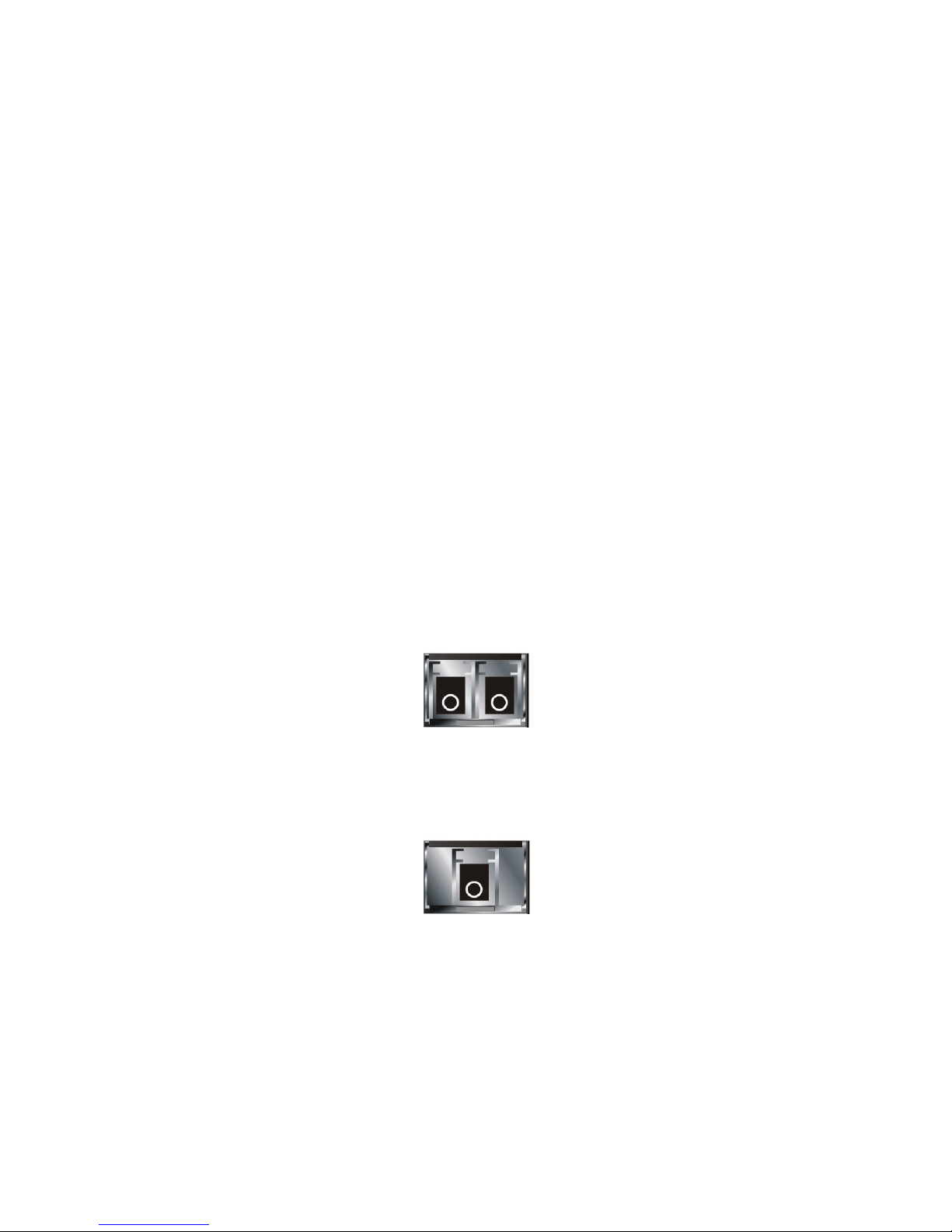
⎯ 1000Mbps LC, SM 10km, SFP Fiber transceiver with DDM
Fig. 1-4 Front View of 1000Base-SX/LX LC, SFP Fiber Transceiver
Fig. 1-5 Front View of 1000Base-LX BiDi SFP Fiber Transceiver
7
r
2. Installation
2-1. Starting the 16-Port GbE Web Smart Switch Up
This section describes how to install the Web Smart Switch and its components, and also includes the
following information:
- Hardware and Cable Installation
- Management Station Installation
- Software booting and configuration
2-1-1. Hardware and Cable Installation
At the beginning, please do this first:
⇒ Wear a grounding device to avoid the damage from electrostatic discharge
⇒ Be sure that power switch is OFF before you insert the power cord to power source
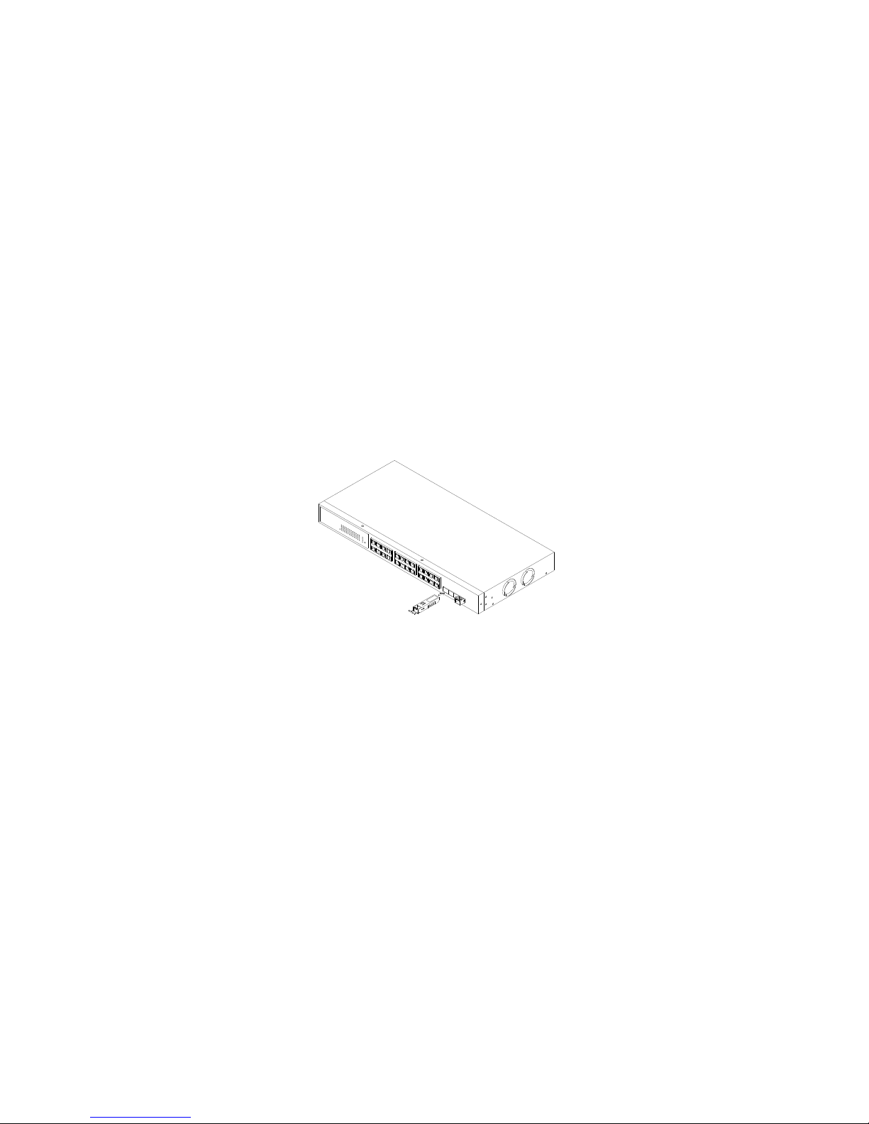
•Installing Optional SFP Fiber Transceivers to the 16-Port GbE Web Smart Switch
Note: If you have no modules, please skip this section.
• Connecting the SFP Module to the Chassis:
The optional SFP modules are hot swappable, so you can plug or unplug it before or after powering
on.
1. Verify that the SFP module is the right model and conforms to the chassis
2. Slide the module along the slot. Also be sure that the module is properly seated against the slot
socket/connector
Fig. 2-1 Installation of Optional SFP Fiber Transceive
3. Install the media cable for network connection
4. Repeat the above steps, as needed, for each module to be installed into
slot(s)
5. Have the power ON after the above procedures are done
8

• TP Port and Cable Installation
⇒ In the switch, TP ports support MDI/MDI-X auto-crossover, so both types of cable, straight-through
(Cable pin-outs for RJ-45 jack 1, 2, 3, 6 to 1, 2, 3, 6 in 10/100M TP; 1, 2, 3, 4, 5, 6, 7, 8 to 1, 2, 3, 4, 5,
6, 7, 8 in Gigabit TP) and crossed-over (Cable pin-outs for RJ-45 jack 1, 2, 3, 6 to 3, 6, 1, 2) can be
used.
⇒ Use Cat. 5 grade RJ-45 TP cable to connect to a TP port of the switch and the other end is connected
to a network-aware device such as a workstation or a server.
⇒ Repeat the above steps, as needed, for each RJ-45 port to be connected to a Gigabit 10/100/1000 TP
device.
Now, you can start to operate the switch.
• Power On
The switch supports 100-240 VAC, 50-60 Hz power supply. The power supply will automatically
convert the local AC power source to DC power. It does not matter whether there is any connection
plugged into the switch or not when power on, even modules as well. After the power is on, all LED
indicators will light up and then all off except the power LED remains on. This represents a reset of the
system.
• Firmware Loading
After resetting, the bootloader will load the firmware into the memory. It will take about 30 seconds,
after that, the switch will flash all the LEDs once and automatically performs self-test and is in ready state.
2-1-2. Cabling Requirements
To help ensure a successful installation and keep the network performance good, please take a
care of the cabling requirement. Cables used with incorrect specifications will render the LAN to work
poorly.
9

2-1-2-1. Cabling Requirements for TP Ports
⇒ For Fast Ethernet TP network connection
⎯ The grade of the cable must be Cat. 5 or Cat. 5e with a maximum length of 100 meters.
⇒ Gigabit Ethernet TP network connection
⎯ The grade of the cable must be Cat. 5 or Cat. 5e with a maximum length of 100 meters. Cat. 5e is
recommended.
2-1-2-2. Cabling Requirements for 1000SX/LX SFP Module
Basically, there are two categories of fiber, multi mode (MM) and single mode (SM). The later is
categorized into several classes by the distance it supports. They are SX, LX, LHX, XD, and ZX. From
the viewpoint of connector type, there mainly are LC and BIDI.
⎯ Gigabit Fiber with multi-mode LC SFP module
⎯ Gigabit Fiber with single-mode LC SFP module
⎯ Gigabit Fiber with BiDi 1310nm SFP module
⎯ Gigabit Fiber with BiDi 1550nm SFP module
The following table lists the types of fiber that we support and those else not listed here are
available upon request.
Multi-mode Fiber Cable and Modal Bandwidth
IEEE 802.3z
Gigabit Ethernet
1000SX 850nm
1000BaseLX/LHX/XD/ZX
1000Base-LX
Single Fiber
(BIDI)
Table2-1
Multi-mode 62.5/125μm Multi-mode 50/125μm
Modal
Bandwidth
160MHz-Km 220m 400MHz-Km 500m
200MHz-Km 275m 500MHz-Km 550m
Single-mode Fiber 9/125μm
Single-mode transceiver 1310nm 10Km
Single-mode transceiver 1550nm 30, 50Km
Single-Mode
Single-Mode
*20Km
*20Km
Distance
Modal
Bandwidth
TX(Transmit) 1310nm
RX(Receive) 1550nm
TX(Transmit) 1550nm
RX(Receive) 1310nm
Distance
10
2-1-2-3. Switch Cascading in Topology
• Takes the Delay Time into Account
Theoretically, the switch partitions the collision domain for each port in the switch so that you may
up-link the switches unlimitedly. In practice, the network extension (cascading levels & overall diameter)
must follow the constraint of the IEEE 802.3/802.3u/802.3z and other 802.1 series protocol specifications,
in which the limitations are the timing requirement from physical signals defined by 802.3 series
specification of Media Access Control (MAC) and PHY, and timer from some OSI layer 2 protocols such
as 802.1d, 802.1q, LACP and so on.
The fiber, TP cables and devices’ bit-time delay (round trip) are as follows:
1000Base-X TP, Fiber 100Base-TX TP 100Base-FX Fiber
Round trip Delay: 4096 Round trip Delay: 512
Cat. 5 TP Wire: 11.12/m Cat. 5 TP Wire: 1.12/m Fiber Cable: 1.0/m
Fiber Cable : 10.10/m TP to fiber Converter: 56
Bit Time unit : 1ns (1sec./1000 Mega bit)
Sum up all elements’ bit-time delay and the overall bit-time delay of wires/devices must be within
Round Trip Delay (bit times) in a half-duplex network segment (collision domain). For full-duplex operation,
this will not be applied. You may use the TP-Fiber module to extend the TP node distance over fiber optic
and provide the long haul connection.
• Typical Network Topology in Deployment
Bit Time unit: 0.01μs (1sec./100 Mega bit)
Table 2-2
A hierarchical network with minimum levels of switch may reduce the timing delay between server
and client station. Basically, with this approach, it will minimize the number of switches in any one path;
will lower the possibility of network loop and will improve network efficiency. If more than two switches are
connected in the same network, select one switch as Level 1 switch and connect all other switches to it at
Level 2. Server/Host is recommended to connect to the Level 1 switch. This is general if no VLAN or other
special requirements are applied.
11
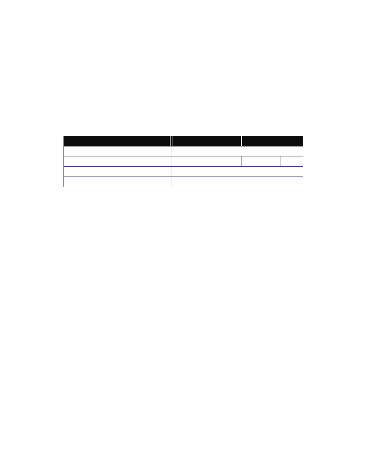
Case1: All switch ports are in the same local area network. Every port can access each other
(See Fig. 2-2).
Fig. 2-2 No VLAN Configuration Diagram
If VLAN is enabled and configured, each node in the network that can communicate each other
directly is bounded in the same VLAN area.
Here VLAN area is defined by what VLAN you are using. The switch supports both port-based
VLAN and tag-based VLAN. They are different in practical deployment, especially in physical location.
The following diagram shows how it works and what the differences are.
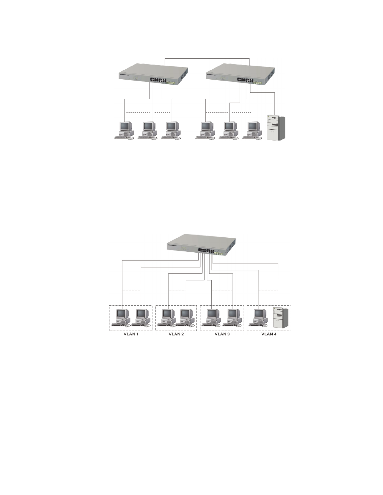
Case2a: Port-based VLAN (See Fig.2-3).
Fig. 2-3 Port-based VLAN Diagram
1. The same VLAN members cannot be in different switches.
2. Every VLAN member cannot access other VLAN members.
3. The switch manager has to assign different names for each VLAN group
at one switch.
12
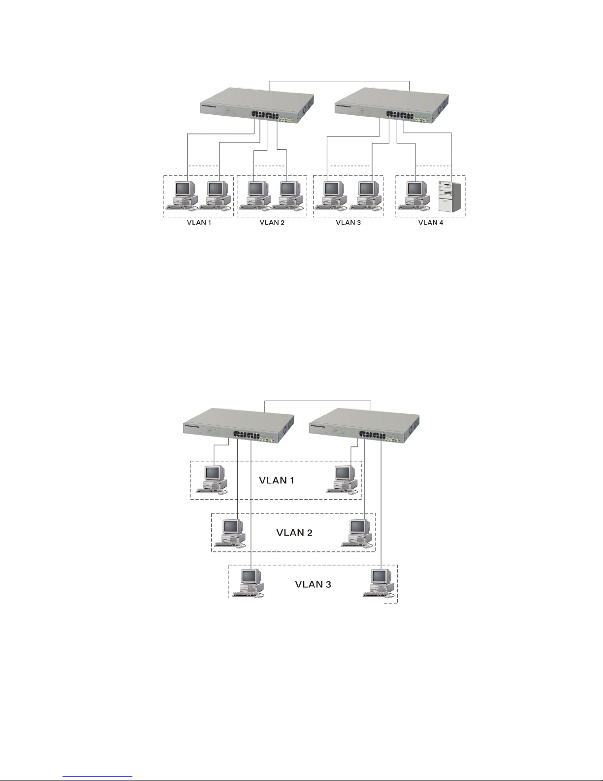
Case 2b: Port-based VLAN (See Fig.2-4).
Fig. 2-4 Port-based VLAN Diagram
1. VLAN1 members cannot access VLAN2, VLAN3 and VLAN4 members.
2. VLAN2 members cannot access VLAN1 and VLAN3 members, but they can access VLAN4
members.
3. VLAN3 members cannot access VLAN1, VLAN2 and VLAN4.
4. VLAN4 members cannot access VLAN1 and VLAN3 members, but they can access VLAN2
members.
Case3a: The same VLAN members can be at different switches with the same VID (See Fig. 2-
5).
Fig. 2-5 Attribute-based VLAN Diagram
13

2-1-3. Configuring the Management Agent of 16-Port GbE Web Smart Switch
In the way of web, the user is allowed to start up the switch management function. Users can use
any one of them to monitor and configure the switch. You can touch them through the following
procedures.
Section 2-1-3-1: Configuring Management Agent of 16-Port GbE Web Smart Switch through Ethernet Port
14
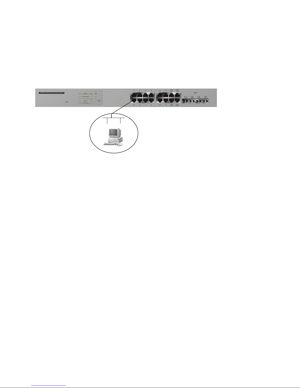
2-1-3-1. Management through Ethernet Port
There are two ways to configure and monitor the switch through the switch’s Ethernet port. They
are Web browser and SNMP manager. We just introduced the first type of management interface. Webbased UI for the switch is an interface in a highly friendly way.
16-PORT GBE WEB SMART SWITCH
Default IP Setting:
IP = 192.168.1.1
Subnet Mask = 255.255.255.0
Default Gateway = 192.168.1.254
Ethernet LAN
Assign a reasonable IP address,
For example:
IP = 192.168.1.100
Subnet Mask = 255.255.255.0
Default Gateway = 192.168.1.254
Fig. 2-6
• Managing 16-Port GbE Web Smart Switch through Ethernet Port
Before starting to use the switch, the IP address setting of the switch should be done, then perform
the following steps:
1. Set up a physical path between the configured switch and a PC by a qualified UTP Cat. 5
cable with RJ-45 connector.
Note: If the PC directly connects to the switch, you have to setup the same subnet mask
between them. However, subnet mask may be different for the PC in the remote site.
Please refer to Fig. 2-6 about the 16-Port GbE Web Smart Switch default IP address
information.
2. Run web browser and follow the menu. Please refer to Chapter 4.
15
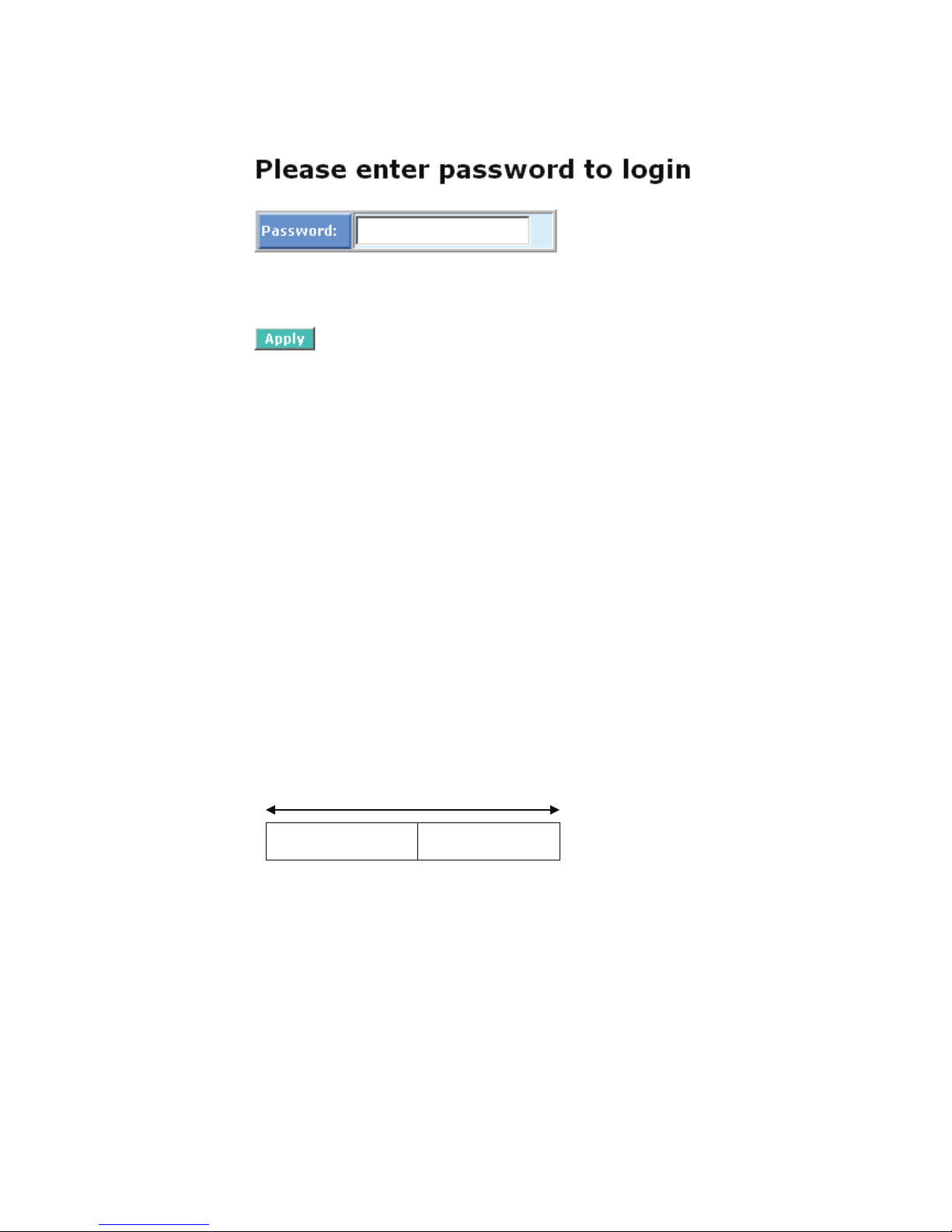
Fig. 2-7 the Login Screen for Web
2-1-4. IP Address Assignment
For IP address configuration, there are three parameters needed to be filled in. They are IP
address, Subnet Mask, Default Gateway and DNS.
IP address:
The address of the network device in the network is used for internet communication. Its address
structure looks as shown in the Fig. 2-8. It is split into predefined address classes or categories.
Each class has its own network range between the network identifier and host identifier in the 32
bits address. Each IP address comprises two parts: network identifier (address) and host identifier
(address). The former indicates the network where the addressed host resides, and the latter indicates
the individual host in the network which the address of the host refers to. And the host identifier must be
unique in the same LAN. Here are the terms of IP addresses we used in version 4, known as IPv4.
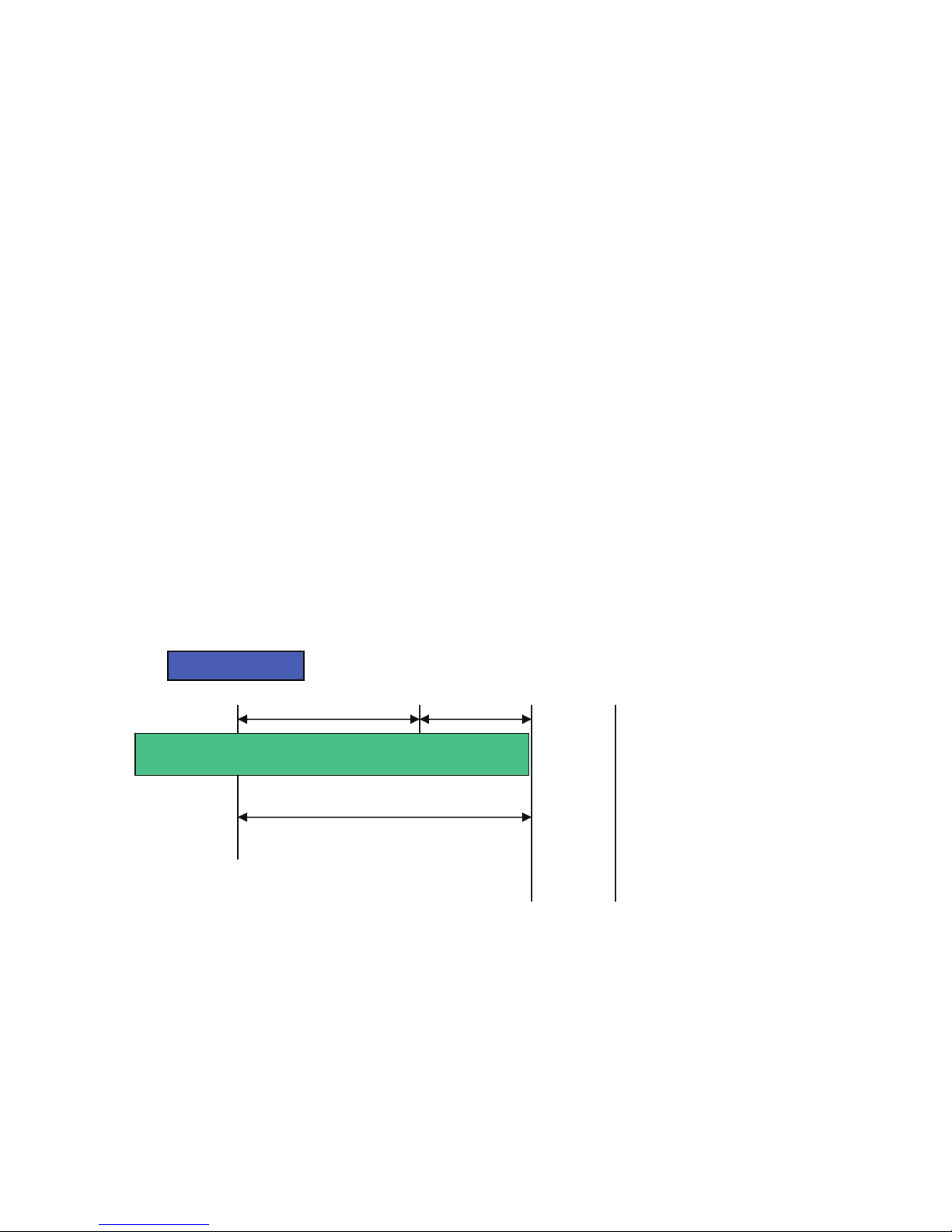
32 bits
Network identifier Host identifier
Fig. 2-8 IP address structure
16

IP addresses are divided into three classes, class A, class B and class C. The rest of the IP
addresses are for multicast and broadcast. The bit length of the network prefix is the same as that of the
subnet mask and is denoted as IP address/X, for example, 192.168.1.0/24. Each class has its address
range described below.
Class A:
Address is less than 126.255.255.255. There are a total of 126 networks can be defined because
the address 0.0.0.0 is reserved for default route and 127.0.0.0/8 is reserved for loopback function.
Bit # 0 1 7 8 31
0
Network address Host address
Class B:
IP address range between 128.0.0.0 and 191.255.255.255. Each class B network has a 16-bit
network prefix followed 16-bit host address. There are 16,384 (2^14)/16 networks able to be defined with
a maximum of 65534 (2^16 –2) hosts per network.
Bit # 01 2 15 16 31
10
Network address Host address
Class C:
IP address range between 192.0.0.0 and 223.255.255.255. Each class C network has a 24-bit
network prefix followed 8-bit host address. There are 2,097,152 (2^21)/24 networks able to be defined
with a maximum of 254 (2^8 –2) hosts per network.
Bit # 0 1 2 3 23 24 31
110
Network address Host address
17
t
N
Class D and E:
Class D is a class with first 4 MSB (Most significance bit) set to 1-1-1-0 and is used for IP Multicast.
See also RFC 1112. Class E is a class with first 4 MSB set to 1-1-1-1 and is used for IP broadcast.
According to IANA (Internet Assigned Numbers Authority), there are three specific IP address
blocks reserved and able to be used for extending internal network. We call it Private IP address and is
listed below:
Class A 10.0.0.0 --- 10.255.255.255
Class B 172.16.0.0 --- 172.31.255.255
Class C 192.168.0.0 --- 192.168.255.255
Please refer to RFC 1597 and RFC 1466 for more information.
Subnet mask:
It means the sub-division of a class-based network or a CIDR block. The subnet is used to
determine how to split an IP address to the network prefix and the host address in bitwise basis. It is
designed to utilize IP address more efficiently and easily manage IP network.
For a class B network, 128.1.2.3, it may have a subnet mask 255.255.0.0 in default, in which the
first two bytes is with all 1s. This means more than 60 thousand nodes in flat IP addresses will be at the
same network. It’s too large to manage practically. Now if we divide it into smaller network by extending
the network prefix from 16 bits to, say 24 bits, that’s using its third byte to subnet this class B network.
Now it has a subnet mask 255.255.255.0, in which each bit of the first three bytes is 1. It’s now clear that
the first two bytes are used to identify the class B network, the third byte is used to identify the subnet
within this class B network and, of course, the last byte is the host number.
Not all IP addresses are available in the sub-netted network. Two special addresses are reserved.
They are the addresses with all zero’s and all one’s host number. For example, an IP address
128.1.2.128. All 0s mean the network itself, and all 1s mean IP broadcast.
10000000.00000001.00000010.1 0000000
etwork
25 bits
All 0s = 128.1.2.128
All 1s= 128.1.2.255
Subne
1 0000000
1 1111111
18

In this diagram, you can see the subnet mask with 25-bit long, 255.255.255.128, contains 126
members in the sub-netted network. Another is that the length of network prefix equals the number of the
bit with 1s in that subnet mask. With this, you can easily count the number of IP addresses matched. The
following table shows the results.
Prefix Length No. of IP matched No. of Addressable IP
/32
1 -
/31
/30
/29
/28
/27
/26
/25
/24
/23
/22
/21
/20
/19
/18
/17
2 -
4 2
8 6
16 14
32 30
64 62
128 126
256 254
512 510
1024 1022
2048 2046
4096 4094
8192 8190
16384 16382
32768 32766
/16
65536 65534
Table 2-3
According to the scheme above, a subnet mask 255.255.255.0 will partition a network with the
class C. It means there will have a maximum of 254 effective nodes existing in this sub-netted network
and is considered a physical network in an autonomous network. So it owns an IP address which may
look like 168.1.2.0.
With the subnet mask, a bigger network can be cut into smaller pieces. If we want to have more
than two independent networks, a partition to the network must be performed. In this case, subnet mask
must be applied.
19
For different network applications, the subnet mask may look like 255.255.255.240. This means it
is a small network accommodating a maximum of 15 nodes.
Default gateway:
For the routed packet, if the destination is not in the routing table, all the traffic is put into the
device with the designated IP address, known as default router. Basically, it is a routing policy.
For assigning an IP address to the switch, you just have to check what the IP address of the
network will be connected with the switch. Use the same network address and append your host address
to it.
First, IP Address: as shown in the Fig. 2-9, enter “192.168.1.1”, for instance. For sure, an IP
address such as 192.168.1.x must be set on your PC.
Second, Subnet Mask: as shown in the Fig. 2-9, enter “255.255.255.0”. Any subnet mask such as
255.255.255.x is allowable in this case.
Fig. 2-9
20
2-2. Typical Applications
The 24-Port GbE Web Smart Switch provides auto MDIX on its TP ports and supports fiber types
like: LC and BiDi SFP for removable modules on its four slots. For more details on the specification of the
switch, please refer to Appendix A.
The switch is suitable for the following applications.
⎯ Central Site/Remote site application is used in carrier or ISP (See Fig. 2-10)
⎯ Peer-to-peer application is used in two remote offices (See Fig. 2-11)
⎯ Office network(See Fig. 2-12)
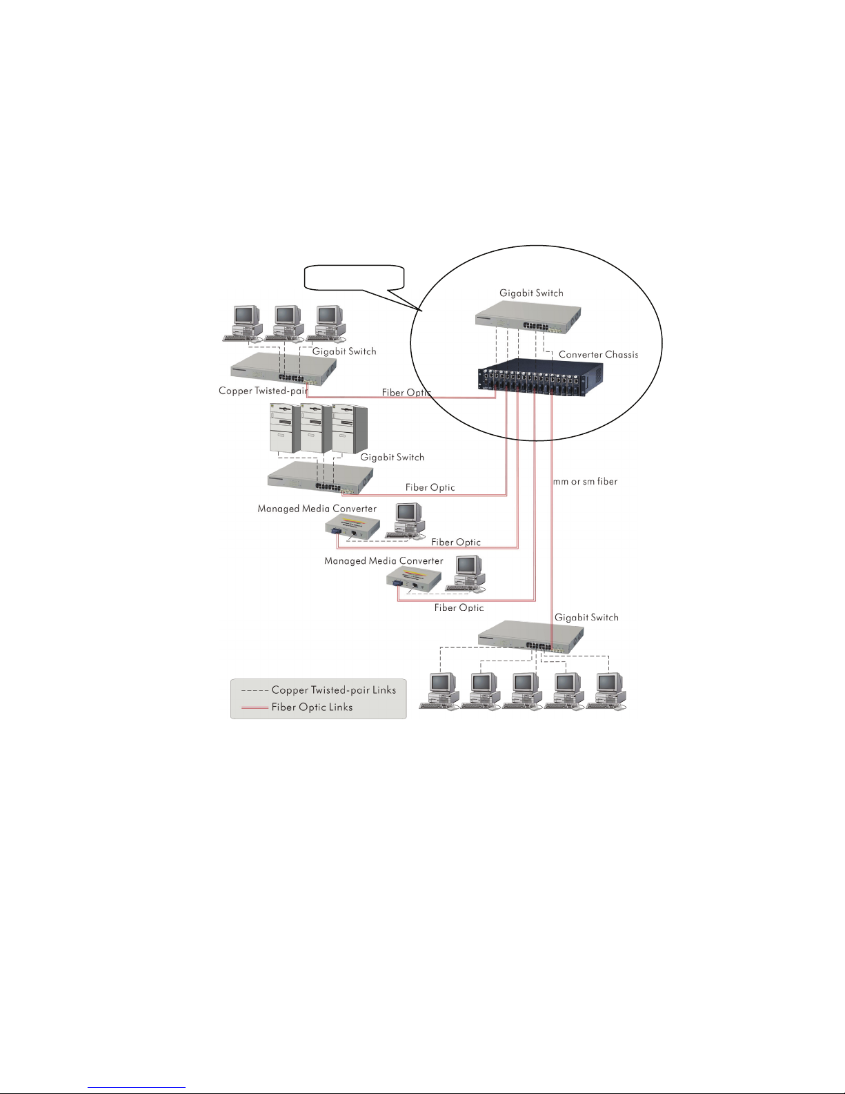
Central Site
Fig. 2-10 Network Connection between Remote Site and Central Site
Fig. 2-10 illustrates how the switches and the various devices form the network infrastructure in a
large-scale network.
21
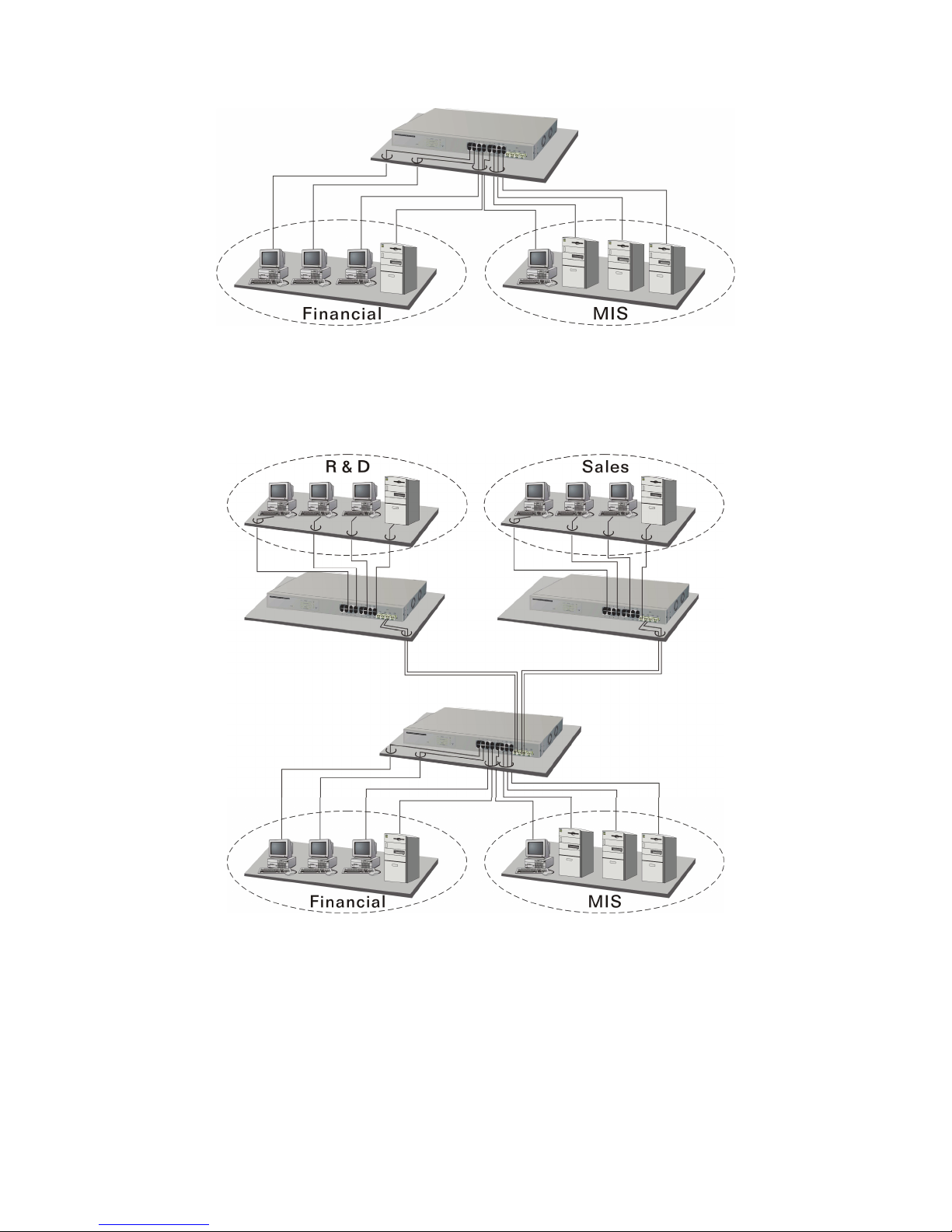
Fig. 2-11 Peer-to-peer Network Connection
Fig. 2-12 Office Network Connection
22

3. Basic Concept and Management
This chapter will explain the basic features and how they work.
3-1. What is Ethernet?
Ethernet was originated and implemented at Xerox in Palo Alto, CA in 1973 and was successfully
commercialized by Digital Equipment Corporation (DEC), Intel and Xerox (DIX) in 1980. In 1992, Grand
Junction Networks unveiled a new high speed Ethernet with the same characteristic of the original
Ethernet but operated at 100Mbps, now called Fast Ethernet. This means Fast Ethernet inherits the same
frame format, CSMA/CD, software interface. In 1998, Gigabit Ethernet was rolled out and provided
1000Mbps. Now 10G/s Ethernet is being developed. Although these Ethernet have different speeds, they
still use the same basic functions. So they are compatible in software and can connect to each other
almost without limitation. The transmission media may be the only problem.
Fig. 3-1 IEEE 802.3 reference model vs. OSI reference mode
In Fig. 3-1, we can see that Ethernet is made up of three portions, including logical link control
(LLC), media access control (MAC), and physical layer. The Data link layer performs splitting data into
frame for transmitting, receiving acknowledge frame, error checking and re-transmitting when not
received correctly as well as provides an error-free channel upward to the network layer.
23

Data
Link
Layer
IEEE802.3 CSMA/CD MAC
IEEE 802.3 PLS
Physical
Layer
IEEE 802.3
MAU
IEEE 802.2 LLC
CS
MII
ANSI X3T9.5 PMD
Coaxial/STP/UTP
Fiber
This above diagram shows the Ethernet architecture, LLC sub-layer and MAC sub-layer, which
respond to the Data Link layer, and transceivers, which respond to the Physical layer in OSI model. In
this section, we are mainly describing the MAC sub-layer.
Logical Link Control (LLC)
Data link layer is composed of both the sub-layers of MAC and MAC-client. Here, the MAC client
may be logical link control or bridge relay entity.
Logical link control supports the interface between the Ethernet MAC and upper layers in the
protocol stack, usually the Network layer, which is nothing to do with the nature of the LAN. So it can
operate over other different LAN technology such as Token Ring, FDDI and so on. Likewise, for the
interface to the MAC layer, LLC defines the services with the interface independent of the medium access
technology and with some of the nature of the medium itself.
24
 Loading...