

Versitron SG70660M Installation Manual

SG70660M
Web Smart 6-Port Gigabit Ethernet Switch
with one mini-GBIC Port
Installation Guide
© February 2006
SG70660M Rev. B
VERSITRON, Inc.
83 Albe Drive / Suite C
Newark, DE 19702
www.versitron.com

The information contained in this document is subject to change without prior notice. Copyright (C). All
Rights Reserved.
TRADEMARKS
Ethernet is a registered trademark of Xerox Corp.
WARNING:
This equipment has been tested and found to comply with the limits for a Class A digital device, pursuant
to Part 15 of the FCC Rules. These limits are designed to provide reasonable protection against harmful
interference when the equipment is operated in a commercial environment. This equipment generates,
uses, and can radiate radio frequency energy and if not installed and used in accordance with the
instruction manual may cause harmful interference in which case the user will be required to correct the
interference at user’s own expense.
NOTICE:
(1) The changes or modifications not expressively approved by the party responsible for compliance
could void the user's authority to operate the equipment.
(2) Shielded interface cables and AC power cord, if any, must be used in order to comply with
the emission limits.
CISPR A COMPLIANCE:
This device complies with EMC directive of the European Community and meets or exceeds the following
technical standard.
EN 55022 - Limits and Methods of Measurement of Radio Interference Characteristics of Information
Technology Equipment. This device complies with CISPR Class A.
WARNING: This is a Class A product. In a domestic environment this product may cause radio interference in which case the user may be required to take adequate measures.
CE NOTICE
Marking by the symbol indicates compliance of this equipment to the EMC directive of the
European Community. Such marking is indicative that this equipment meets or exceeds the following
technical standards:
EN 55022: Limits and Methods of Measurement of Radio Interference characteristics of
Information
Technology Equipment.
EN 50082/1: Generic Immunity Standard -Part 1: Domestic Commercial and Light Industry.
EN 60555-2: Disturbances in supply systems caused by household appliances and similar electrical
equipment - Part 2: Harmonics.
2

PROPRIETARY DATA
All data in this manual is proprietary and may not be disclosed,
used or duplicated, for procurement or manufacturing purposes,
without prior written permission by VERSITRON, Inc.
All VERSITRON products are warranted for a period of one year from date of delivery.
VERSITRON reserves the right to repair or, at our option, replace parts which during
normal usage prove to be defective during the warranty period provided that:
1. You call VERSITRON at 302-894-0699 or 800-537-2296 and obtain a Return
Maintenance Authorization (RMA) Number. Please reference your RMA number on the
outside of the box in which the item is shipped.
2. Shipping charges are pre-paid.
No other warranty is expressed or implied and we are not liable for consequential damages. For
repairs outside of the warranty period, the same procedure must be followed.
3

Table of Contents
1. Introduction .................................................................................................. 6
1.1 Features ...................................................................................................................7
1.2 Product Panels ......................................................................................................... 7
1.3 LED Indicators .......................................................................................................... 8
1.4 Specifications ........................................................................................................... 8
2. Installation .................................................................................................. 10
2.1 Unpacking ............................................................................................................... 10
2.2 Safety Cautions ...................................................................................................... 10
2.3 Mounting the Switch ................................................................................................ 10
2.4 Applying Power ........................................................................................................ 11
2.5 Reset Button .......................................................................................................... 11
2.6 Making UTP Connections ....................................................................................... 12
2.7 Making Fiber Connection ........................................................................................ 13
2.8 LED Indication ........................................................................................................ 14
2.9 Configuring IP Address and Password for the Switch ............................................. 14
3. Advanced Functions .................................................................................. 15
3.1 Abbreviation ............................................................................................................. 15
3.2 QoS Function .......................................................................................................... 16
3.2.1 Packet Priority Classification ................................................................................ 17
3.2.2 Priority Class Queues .......................................................................................... 17
3.2.3 Egress Service Policy .......................................................................................... 17
3.3 VLAN Function ......................................................................................................... 18
3.3.1 VLAN Operation .................................................................................................... 18
3.3.2 Ingress Rules ....................................................................................................... 18
3.3.2.1 802.1Q Tag Aware Per port setting .................................................................... 18
3.3.2.2 Keep Tag Per port setting .................................................................................. 18
3.3.2.3 Drop Untag Per Port Setting .............................................................................. 19
3.3.2.4 Drop Tag Per Port Setting .................................................................................. 19
3.3.3 Ingress Default Tag Per Port Setting ..................................................................... 19
3.3.4 Packet Tag Information ......................................................................................... 19
3.3.5 VLAN Group Table Configuration ........................................................................... 20
3.3.6 VLAN Classification ............................................................................................... 20
3.3.7 Packet Forwarding ................................................................................................ 20
3.3.8 Egress Tagging Rules .......................................................................................... 21
3.3.8.1 Egress Settings ................................................................................................. 21
3.3.9 Summary of VLAN Function ................................................................................. 21
4. Web Management ....................................................................................... 22
4.1 Start Browser Software and Making Connection ..................................................... 22
4

4.2 Login to the Switch Unit ........................................................................................... 22
4.3 Main Management Menu .......................................................................................... 23
4.4 System .................................................................................................................... 24
4.4.1 Management VLAN ............................................................................................... 25
4.5 Ports ........................................................................................................................ 26
4.6 VLANs ..................................................................................................................... 27
4.6.1 Port-based VLAN Mode ......................................................................................... 28
4.6.2 Port-based VLAN ISP Mode .................................................................................. 29
4.6.3 Advanced VLAN Mode ........................................................................................... 30
4.6.3.1 Ingress Default Tag ............................................................................................ 31
4.6.3.2 Ingress Settings ................................................................................................. 32
4.6.3.3 Egress Settings ................................................................................................. 33
4.6.3.4 VLAN Groups ..................................................................................................... 34
4.6.4 Important Notes for VLAN Configuration ................................................................ 35
4.7 Aggregation .............................................................................................................. 36
4.8 Quality of Service .................................................................................................... 37
4.8.1 802.1p Mapping .................................................................................................... 38
4.8.2 DSCP Mapping ..................................................................................................... 39
4.8.3 QoS Service Policy .............................................................................................. 40
4.9 Port Mirroring ........................................................................................................... 41
4.10 Statistics ................................................................................................................ 42
4.11 Reboot System ...................................................................................................... 43
4.12 Restore Default ..................................................................................................... 43
4.13 Update Firmware ................................................................................................... 43
4.14 Logout ................................................................................................................... 43
Appendix. Factory Default Settings ............................................................... 44
5
1. Introduction
The SG70660M is a managed 6-port Gigabit Ethernet switch which is featured with five copper
ports, one mini-GBIC (SFP) port and the following advantages in a small footprint box:
Plug and Play
The switch is shipped with factory default configuration which behaves like an unmanaged
Gigabit switch for workgroup. It provides five 10/100/1000Mbps copper ports for connections to
Ethernet, Fast Ethernet, and Gigabit Ethernet devices. With the featured auto-negotiation
function, the switch can detect and configure the connection speed and duplex automatically. The
switch also provides auto MDI/MDI-X function, which can detect the connected cable and switch
the transmission wire pair and receiving pair automatically. This auto-crossover function can
simplify the type of network cables used.
Fiber Connectivity
The mini-GBIC (SFP) port can be installed with an optional SFP optical fiber transceiver to support one
Gigabit fiber connection when needed.
Web Management
The switch is embedded with an Http server which provides management functions for
advanced network functions including Port Control, Quality of Service, and Virtual LAN functions.
The manage- ment can be performed via Web browser based interface over TCP/IP network.
Quality of Service
For advanced application, the switch is featured with powerful Quality of Service (QoS)
function which can classify the priority for received network frames based on the ingress port
and frame contents. Furthermore, many service priority policies can be configured for egress
operation in per-port basis.
Virtual LAN (VLAN)
For increasing Tagged VLAN applications, the switch is also featured with powerful VLAN
function to fulfill the up-to-date VLAN requirements. The switch supports both port-based VLAN
and tagged VLAN in per-port basis.
6
1.1 Features
LED Indicators
10/100/1000M Copper Ports
Basic functions
Provides 5 10/100/1000Mbps Gigabit Ethernet ports and 1 SFP port
Provides in-band web-based management interface
All copper ports support auto-negotiation and auto-MDI/MDI-X detection
Provides full wire speed forwarding
Supports 802.3x flow control for full-duplex and backpressure for half-duplex
Provides port status, statistic monitoring and control function
Supports port-based and 802.1Q Tag-based VLAN
Provides QoS function
Provides port link aggregation (trunking) function
Provides port mirroring function
Management functions
Web-based browsing interface
Port configuration control and status monitoring
Quality of Service (QoS) control for packet traffic
Port-based and Tagged Virtual LAN (VLAN) function
Link aggregation (port trunking) function
Port mirroring function
In-band embedded firmware upgrade function
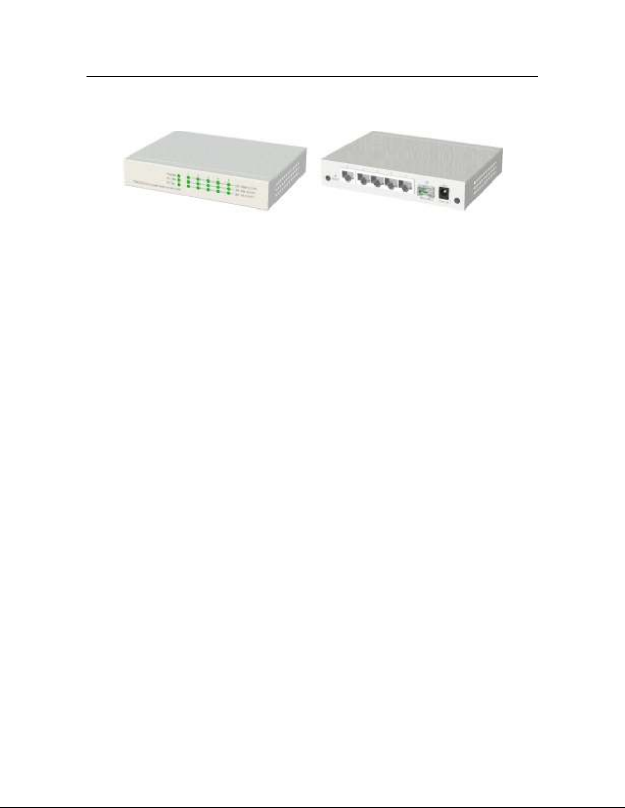
1.2 Product Panels
The following figure illustrates the front panel and rear panel of the switch:
7
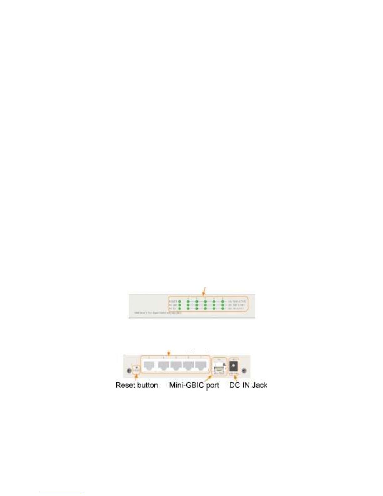
Front panel
Rear panel

1.3 LED Indicators
LED Function
POWER Power status
LNK/1000M/ACT Network port 1000M link status (Port 1 - Port 5)
LNK/100M/ACT Network port 100M link status (Port 1 - Port 5)
LNK/10M/ACT Network port 10M link status (Port 1 - Port 5)
P6 LNK Port 6 1000M link status
P6 OL Port 6 optical link status
1.4 Specifications
10/100/1000 Copper Ports
Compliance IEEE 802.3 10Base-T, IEEE 802.3u 100Base-TX,
IEEE 802.3u 1000Base-T
Connectors Shielded RJ-45 jacks
Pin assignments Auto MDI/MDI-X detection
Configuration Auto-negotiation or software control
Transmission rate 10Mbps, 100Mbps, 1000Mbps
Duplex support Full/Half duplex
Network cable Cat.5 UTP
1000Mbps Mini-GBIC Fiber Port
Compliance IEEE 802.3z 1000Base-SX/LX (mini-GBIC)
Connectors SFP for optional SFP type fiber transceivers
Configuration Auto/Forced, 1000Mbps, Full duplex
Transmission rate 1000Mbps
Network cables MMF 50/125 60/125, SMF 9/125
Eye safety IEC 825 compliant
Switch Functions
MAC Addresses Table 8K entries
Forwarding & filtering Non-blocking, full wire speed
Switching technology Store and forward
Maximum packet length 1526 bytes
Flow control IEEE 802.3x pause frame base for full duplex operation
Back pressure for half duplex operation
VLAN function Port-based VLAN and IEEE 802.1Q Tag-based VLAN
QoS function Port-based, 802.1p-based, IP DSCP-based
8

Port control Port configuration control via software management
Aggregation Link aggregation (trunking)
Port Mirroring Mirror received frames to a sniffer port
LED Indicators
System Power status
Per copper port Port link/activity status, speed status
Port 6 Port link status, optical link status
Software Management Functions
Interfaces Web browser
Management objects System configuration - IP settings, Name, Password
Port configuration control and status
VLAN function settings
QoS function settings
Link aggregation settings
Port mirroring settings
Reboot, restore factory default, update firmware
Port Statistic
DC Power Input
Interfaces DC Jack ( -D 6.3mm / + D 2.0mm)
Operating Input Voltages +7VDC(+/-5%)
Power consumption 3.6W max. @7.5V
Mechanical
Dimension (base) 144 x 104.5 x 26 mm
Housing Enclosed metal with no fan
Mounting Desktop mounting, wall mounting
Environmental
Operating Temperature Typical 0oC ~ 40oC
Storage Temperature -20oC ~ 70oC
Relative Humidity 10% ~ 90%
Electrical Approvals
FCC Part 15 rule Class A
CE EMC, CISPR22 Class A
9
2. Installation
2.1 Unpacking
The product package contains:
The switch unit
One product CD-ROM
2.2 Safety Cautions
To reduce the risk of bodily injury, electrical shock, fire, and damage to the product, observe
the following precautions.
Do not service any product except as explained in your system documentation.
Opening or removing covers may expose you to electrical shock.
Only a trained service technician should service components inside these compartments.
If any of the following conditions occur, unplug the product from the electrical outlet and
replace the part or contact your trained service provider:
- The power cable, extension cable, or plug is damaged.
- An object has fallen into the product.
- The product has been exposed to water.
- The product has been dropped or damaged.
- The product does not operate correctly when you follow the operating instructions.
Do not push any objects into the openings of your system. Doing so can cause fire or
electric shock by shorting out interior components.
Operate the product only from the type of external power source indicated on the
electrical ratings label. If you are not sure of the type of power source required, consult
your service provider or local power company.
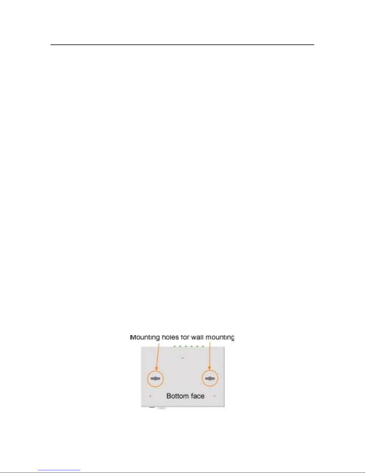
2.3 Mounting the Switch
The switch can be mounted on a desktop or shelf or a wall. Make sure that there is proper
heat dissipation from and adequate ventilation around the device. Do not place heavy objects on the
device.
10

2.4 Applying Power
Before you begin the installation, check the AC voltage of your area. The AC power adapter which is
used to supply the DC power for the unit should have the AC voltage matching the commercial power
voltage in your area.
The AC Power Adapter Specifications
AC input power: AC power voltage of your area, options
- Rated AC120V/60Hz DC7.5V 1A
Rated AC230V/50Hz DC7.5V 1A
Rated AC100V/50-60Hz DC7.5V
1A Rated AC100V/50-60Hz DC5V
1A Rated AC240V/50Hz DC7.5V
1A
Steps to apply the power to the product are:
1. Connect power adapter DC plug to the DC input jack located on the back of the unit
before connecting to the AC outlet.
2. Connect the power adapter to the AC outlet.
3. Check Power LED indication.
Note: Before you begin the installation, check the AC voltage of your area. The AC power
adapter which is used to supply the DC power for the unit should have the AC voltage
matching the commercial power voltage in your area.
2.5 Reset Button
The reset button is used to perform a reset to the switch. It is not used in normal cases and can be
used for diagnostic purpose. If any network hanging problem is suspected, it is useful to push the
button to reset the switch without turning off the power. Check whether the network is recovered.
The button can also be used to restore the software configuration settings to factory default values.
The operations are:
Operation Function
Press the button more than 5 seconds when power up Restore factory default settings
Press the button and release during switch operation Reboot the switch
11

2.6 Making UTP Connections
The 10/100/1000 copper ports supports the following connection types and distances:
Network Cables
10BASE-T: 2-pair UTP Cat. 3,4,5 , EIA/TIA-568B 100-ohm
100BASE-TX: 2-pair UTP Cat. 5, EIA/TIA-568B 100-ohm
1000BASE-T: 4-pair UTP Cat. 5 or higher (Cat.5e is recommended), EIA/TIA-568B 100-ohm
Link distance: Up to 100 meters
Auto MDI/MDI-X Function
This function allows the port to auto-detect the twisted-pair signals and adapts itself to form a
valid MDI to MDI-X connection with the remote connected device automatically. No matter a
straight through cable or crossover cable is connected, the ports can sense the receiving pair
automatically and configure itself to match the rule for MDI to MDI-X connection. It simplifies the
cable installation.
Auto-negotiation Function
The ports are featured with auto-negotiation function and full capability to support connection to
any Ethernet devices. The port performs a negotiation process for the speed and duplex
configuration with the connected device automatically when each time a link is being established. If
the connected device is also auto-negotiation capable, both devices will come out the best
configuration after negotiation process. If the connected device is incapable in auto-negotiation,
the switch will sense the speed and use half duplex for the connection.
Port Configuration Management
For making proper connection to an auto-negotiation incapable device, it is suggested to use port
con- trol function via software management to set forced mode and specify speed and duplex mode
which match the configuration used by the connected device.
12

2.7 Making Fiber Connection
The mini-GBIC (SFP) port must be installed with an SFP fiber transceiver for making fiber
connec- tion. Your switch may come with an SFP transceiver pre-installed when it is shipped.
Installing SFP Fiber Transceiver
To install an SFP fiber transceiver into mini-GBIC port, the steps are:
1. Turn off the power to the switch.
2. Insert the SFP fiber transceiver into the mini-GBIC port. Normally, a bail is provided for every
SFP transceiver. Hold the bail and make insertion.
3. Until the SFP transceiver is seated securely in the slot, place the bail in lock position.
Connecting Fiber Cables
LC connectors are commonly equipped on most SFP transceiver modules. Identify TX and RX
connector before making cable connection. The following figure illustrates a connection
example between two fiber ports:
Make sure the Rx-to-Tx connection rule is followed on the both ends of the fiber cable.
Network Cables
Multimode (MMF) - 50/125, 62.5/125
Single mode (SMF) - 9/125
13

2.8 LED Indication
LED Function State Interpretation
POWER Power status ON The power is supplied to the switch.
OFF The power is not supplied to the
switch.
LNK/1000M/ACT Port link status ON A 1000M link is established. (No
traffic) BLINK Port link is up and there is
traffic.
OFF Port link is down.
LNK/100M/ACT Port link status ON A 100M link is established. (No
traffic) BLINK Port link is up and there is
traffic.
OFF Port link is down.
LNK/1000M/ACT Port link status ON A 10M link is established. (No
traffic) BLINK Port link is up and there is
traffic. OFF Port link is down.
P6 LNK Port6 link status ON A 1000M link is established on Port
6. BLINK Port 6 link is up and there is
traffic. OFF Port 6 link is down.
P6 OL Port6 optical link ON Optical signal is detected on Port 6.
OFF No optical signal is detected on Port
6.
2.9 Configuring IP Address and Password for the Switch
The switch is shipped with the following factory default settings for software management :
Default
The IP Address is an identification of the switch in a TCP/IP network. Each switch should be
desig- nated a new and unique IP address in the network. Refer to Web management interface for
System Configuration.
The switch is shipped with factory default password 123 for software management.
The password is used for authentication in accessing to the switch via Http web-based interface.
For security reason, it is recommended to change the default settings for the switch before
deploying it to your network. Refer to Web management interface for System Configuration.
IP address of the switch : 192.168.0.2 / 255.255.255.0
14
 Loading...