

Page 1

16-Slot
Media Converter Chassis
Installation Guide
MCC-16
MCC-16R
MCC-16M
MCC-16RM
Revision A
Copyright Sept 2004
VERSITRON, Inc.
83 Albe Drive / Suite C
Newark, DE 19702
www.versitron.com
A040930265
Page 2

The information contained in this document is subject to change without prior notice.
Copyright © VERSITRON. All Rights Reserved.
TRADEMARKS
Ethernet is a registered trademark of Xerox Corp.
WARNING:
This equipment has been tested and found to comply with the limits for a Class A digital device, pursuant
to Part 15 of the FCC Rules. These limits are designed to provide reasonable protection against harmful
interference when the equipment is operated in a commercial environment. This equipment generates,
uses, and can radiate radio frequency energy and if not installed and used in accordance with the
instruction manual may cause harmful interference in which case the user will be required to correct the
interference at his own expense.
NOTICE:
(1) The changes or modifications not expressively approved by the party responsible for
compliance could void the user’s authority to operate the equipment.
(2) Shielded interface cables and AC power cord, if any, must be used in order to comply with the
emission limits.
CISPR A COMPLIANCE:
This device complies with EMC directive of the European Community and meets or exceeds the
following technical standard:
EN 55022 - Limits and Methods of Measurement of Radio Interference Characteristics of Information
Technology Equipment. This device complies with CISPR Class A.
WARNING: This is a Class A product. In a domestic environment this product may cause radio
interference in which case the user may be required to take adequate measures.
CE NOTICE
Marking by the symbol
indicates compliance of this equipment to the EMC directive of the European
Community. Such marking is indicative that this equipment meets or exceeds the following technical
standards:
EN 55022: Limits and Methods of Measurement of Radio Interference characteristics of Information
Technology Equipment.
EN 50082/1:Generic Immunity Standard -Part 1: Domestic Commercial and Light Industry.
EN 60555-2: Disturbances in supply systems caused by household appliances and similar electrical
equipment - Part 2: Harmonics.
ii www.versitron.com
Page 3

PROPRIETARY DATA
All data in this manual is proprietary and may not be disclosed,
used or duplicated, for procurement or manufacturing purposes,
without prior written permission by VERSITRON, Inc.
All VERSITRON products are warranted for a period of one year from date of delivery. VERSITRON
reserves the right to repair or, at our option, replace parts which during normal usage prove to be
defective during the warranty period provided that:
1. You call VERSITRON at 302-894-0699 or 800-537-2296 and obtain a Return Material Authorization
(RMA) Number. Please reference your RMA number on the outside of the box in which the item is
shipped.
2. Shipping charges are pre-paid.
No other warranty is expressed or implied and we are not liable for consequential damages. For repairs
outside of the warranty period, the same procedure must be followed.
WARRANTY
iii www.versitron.com
Page 4

Table of Contents
Chapter 1 - Introduction
1.1 Features.........................................................................................................1
1.2 Technical Specifications...............................................................................1
Chapter 2 - Installation
2.1 Unpacking.....................................................................................................2
2.2 System Units.................................................................................................2
2.2.2 Management Module....................................................................................2
2.2.3 Power Chassis Modules................................................................................2
2.3 Rack Mounting .............................................................................................2
Chapter 3 – Network Management
3.1 Management Functions.................................................................................3
3.2 Protocols Supported......................................................................................3
3.3 Setup for Out-of-band (Console) Management ............................................3
3.4 Setup for In-band Management ....................................................................3
Chapter 4 – Console and Telnet Operation
4.1 IP Menu ......................................................................................................33
4.2 SNMP Menu...............................................................................................33
4.3 View System Status....................................................................................34
4.4 View Converter Slots Status.......................................................................34
4.5 Restore Default Values...............................................................................34
4.6 Security Manager........................................................................................34
4.7 Update Firmware ........................................................................................34
4.8 Reboot System............................................................................................34
Chapter 5 – SNMP Management
5.1 Configuring SNMP Settings via Console Operation ..................................35
5.2 SNMP Private MIB ....................................................................................35
5.3 SNMP Traps ...............................................................................................36
Chapter 6 – Web Management
6.1 Start Browser Software and Making Connection .......................................37
6.2 Login to the System Unit............................................................................37
6.3 Converter Status .........................................................................................37
6.4 System Status..............................................................................................37
6.5 Administrator Menu ...................................................................................37
6.5.1 Basic ...........................................................................................................37
6.5.2 Console Port Information ...........................................................................37
6.5.3 Security Manager........................................................................................37
6.5.4 Image Refresh Time ...................................................................................37
6.5.5 Update Firmware ........................................................................................37
6.5.6 Reboot System............................................................................................37
6.6 Slot Icon Operations ...................................................................................37
iv www.versitron.com
Page 5
Chapter 1
Introduction
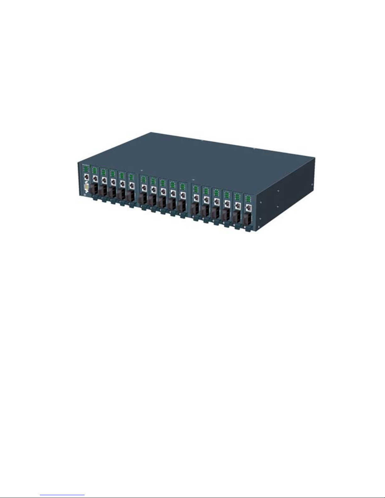
The Model MCC-16 Series Modular Converter System is a manageable media converter chassis that provides 16
slots for up to 16 10/100 Ethernet network Media Converters (MC). A wide range of media converters is
available depending on your variety of network cabling environment. These optional media converters include
10/100 UTP to multimode or single mode fiber cable.
The chassis unit provides a centered power supply to the converter modules and serves as a converter center and
wiring concentrator.
For specifications of the optional media converters please refer to the associated installation guides respectively.
5 www.versitron.com
Page 6

1.1 Features
Some of the key features include:
• Managed Media Converter Center Chassis
• 19-inch rack-mountable 2U chassis
• Managed system accommodates up to 16 media converters
• Highly modularized chassis design with
- modular media converters
- modular management module
- two system power modules for power redundancy
• Provides high availability and maintainability
• Power backup feature with two power chassis
• Visible system status indication
• Supports in-band Telnet, SNMP and web-based management
• Supports out-of-band direct console management
• Management from anywhere and any platform using a web browser
• Easy-to-use point and click user interface
• Photographic quality interface to configure and monitor the system
• Supports in-band event SNMP trap report
• TFTP Software Upgrade
6 www.versitron.com
Page 7

1.2 Technical Specifications
Model MCC-16 MCC-16R MCC-16M MCC-16MR
19-inch Rack Mount Yes Yes Yes Yes
Management No No Yes Yes
Number of MC Slots 16 16 16 16
Number of Power Slots 2 2 2 2
Plug-in Power Modules 1 2 1 2
Module Type AC AC AC AC
Input voltage 90 ~ 264V 90 ~ 264V 90 ~ 264V 90 ~ 264V
Power Supply Rating 60W 60W 60W 60W
Cooling DC Fan DC Fan DC Fan DC Fan
Mechanical
Chassis Height (2U) 3.47 in. (88mm) 3.47 in. (88mm) 3.47 in. (88mm) 3.47 in. (88mm)
Width 17.45 in. (443mm) 17.45 in. (443mm) 17.45 in. (443mm) 17.45 in. (443mm)
Depth 11.82 in. (300mm) 11.82 in. (300mm) 11.82 in. (300mm) 11.82 in. (300mm)
Weight (no MC installed) 11.9 lbs (5.4 kg) 13.2 lbs (6.0 kg) 12.1 lbs (5.5 kg) 13.4 lbs (6.1 kg)
Common Specifications
Environmental
Operating temperature 0 ~ 40
Storage temperature -20 ~ 75
Operating humidity 10 ~ 90%RH
Emission standard
Conducted emission EN55022, CISPR 22
Radiated emission EN55022, CISPR 22
Voltage harmonics EN61000-3-2
Voltage fluctuation & flicker EN61000-3-3
Susceptibility
Electrostatic discharge immunity EN61000-4-2, IEC61000-4-2
Radiated immunity EN61000-4-3, IEC61000-4-3
EFT/Burst immunity EN61000-4-4, IEC61000-4-4
Surge immunity EN61000-4-5, IEC61000-4-5
Continuous wave voltage immunity EN61000-4-6, IEC61000-4-6
PFMF immunity EN61000-4-8, IEC61000-4-8
Voltage DIP/Interrupt immunity EN61000-4-11, IEC61000-4-11
Certifications
FCC Part 15, Class A
CE EMC Class A, EN50081-1, EN50082-1
o
C
o
C
7 www.versitron.com
Page 8

AC Power Chassis Module Specifications
Dimension 7.64 in. (194mm) x 6.15 in. (156mm) x 1.59 in. (40.3mm)
Installation method Plug in to system rear panel
Maintenance Modular design for easy maintenance
AC power switch System power on/off switch
AC power receptacle IEC320 type receptacle
Power status indication Green LED Electric
Input voltage rating 100 ~ 240VAC
Input voltage range 90 ~ 264VAC
Input frequency 47 ~ 63Hz
Input surge current 20A max. @115VAC
Efficiency 75% @ 115VAC full load
Output power 60W
Over current protection All output with short circuit protection
Safety UL / cUL, TUV EN60950
Insulation Resistance >10M Ohm @ DC500V
Dielectric withstands 1500VAC 10mA 1min.
Management Module Specifications
Dimension 4.22 in. (107mm) x 0.95 in. (24mm) x 3.40 in. (86.4mm)
Slot position Slot 0
CPU RISC-based ARM7
RAM size 1M bytes
Flash size 512K bytes
System interface
Connector FutureBus connector
Console interface
Interface RS-232 DTE
Connector 9-pin male D-SUB connector
Baud rate 38400, N, 8, 1, 0
Flow control Disabled
In-band interface
Interface 10/100M LAN port
Connector Shielded RJ-45 MDI
Standard IEEE 802.3 10BASE-T/100BASE-TX
Auto-negotiation Support
LED Indicators
P1, P2 Green LED, power module status
DIAG Green LED, CPU initialization
FAN Green LED, Fan failure indication
CONSOLE Green LED, Console RS-232 Rx activities
LNK/ACT. Green LED, LAN port link and activities status
8 www.versitron.com
Page 9

Management Specifications
Management Interface
Telnet Via direct RS-232 console connection
Telnet Via TCP/IP Telnet software
SNMP agent Via TCP/IP SNMP manager software
HTTP server Via web browser software
Protocols
IPv4 IP version4 RFC791
TCP Transmission Control Protocol RFC793
UDP User Datagram Protocol RFC768
ICMP Internet Control Message Protocol RFC792
SNMP SNMP agent v1 RFC1157
MIB-II Standard MIB RFC1213
TFTP Trivial File Transfer Protocol RFC1350
TELNET Telnet protocol RFC854
HTTP HTTP server for web management RFC1945
Management Objects
Password for access control Set and monitor
System status: CPU, memory, flash, software Monitor
System power 1&2 status Monitor
System fan status Monitor
IP address of the system Set and monitor
Subnet mask of the system Set and monitor
Default gateway IP address Set and monitor
SNMP name information Set and monitor
SNMP location information Set and monitor
SNMP contact information Set and monitor
SNMP community names (up to 4) Set and monitor
SNMP community access right (up to 4) Set and monitor
SNMP trap host IP address (up to 3) Set and monitor
Slot status: MC installed or not Monitor
MC status: media type, speed, duplex Monitor
MC link status of two ports Monitor
Remote MC link status (two KC-300DMs link only) Monitor
SNMP Traps
Cold Start System is powered on and completes initialization
Authentication failure SNMP community authentication failure
Power status The system power 1&2 failure and recovery
Fan failure System fan failure and recovery
Slot # Port A link Slot # MC Port A link down or up
Slot # Port B link Slot # MC Port B link down or up
Slot # PTP link Slot # Remote MC TP Port link change
Update Firmware Via TFTP protocol
Remote boot system
9 www.versitron.com
Page 10
Chapter 2
Installation
2.1 Unpacking
The product package contains:
• The system unit
• One power cord
• One 19-inch rack mounting kit
• Operation Manual
2.2 System Units
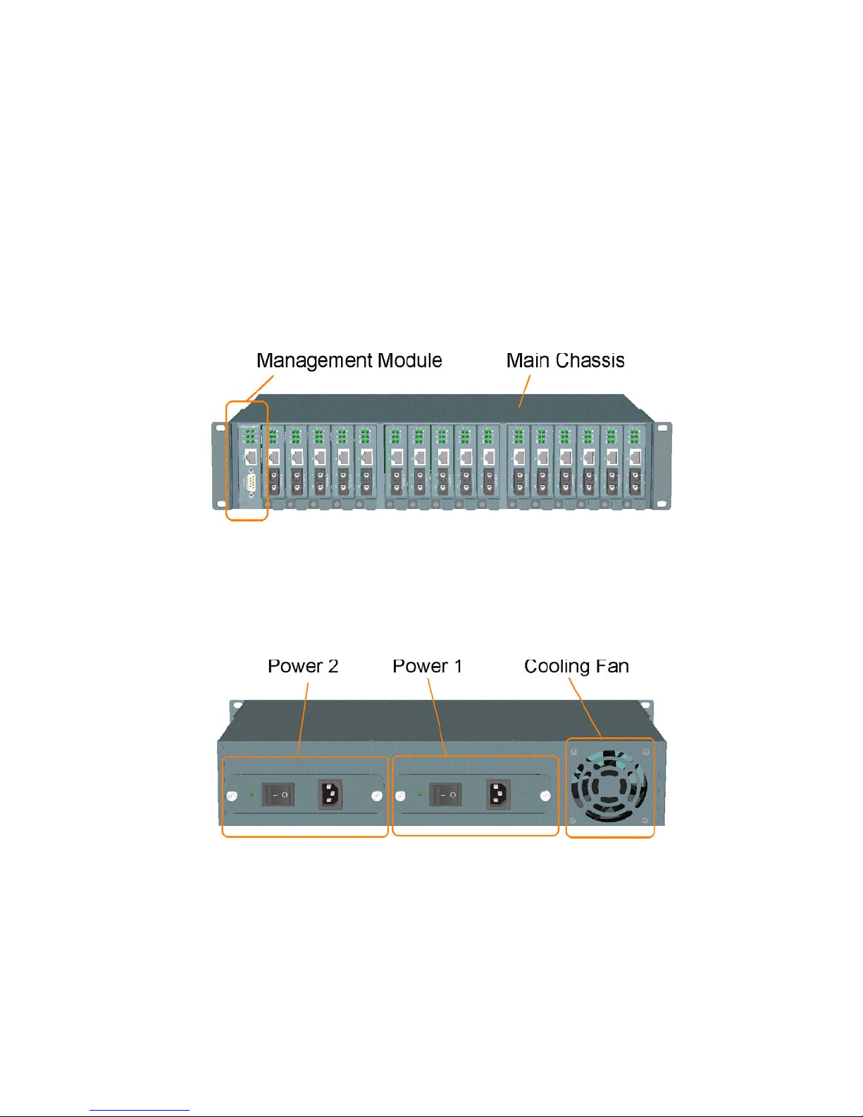
The figure below illustrates the front view of the MCC-16 system:
The type and numbers of the pre-installed media converters may be different depending on the model purchased.
The figure shows a system fully installed with media converters.
The following figure shows the rear view of the MCC-16 chassis with two power slots on the rear panel. Each
power slot can be installed with one AC power supply. Two slots provide the option for redundant power.
Main Chassis: provides insertion slots on front panel for CPU management module and optional add-on media
converters. It also provides two chassis slots on rear for mounting power chassis modules.
Management Module: serves as a management agent to monitor system status and add-on converter modules for
in-band and out-of-band management requests.
AC Power Chassis: provides power for the whole unit. It can receive commercial AC power.
System Cooling Fan: provides forced air to cool down the temperature for the system unit.
10 www.versitron.com
Page 11
2.2.2 Management Module
The chassis comes with one pre-installed Management module. The module facilitates the following functions:
• Direct out-of-band management via RS-232 console port
• SNMP agent to serve in-band management via SNMP protocol
• Telnet console in-band management via TCP/IP protocol
• HTTP host to serve web-based in-band management
• Monitoring all MCs status installed in the system
• Monitoring system power and fan status
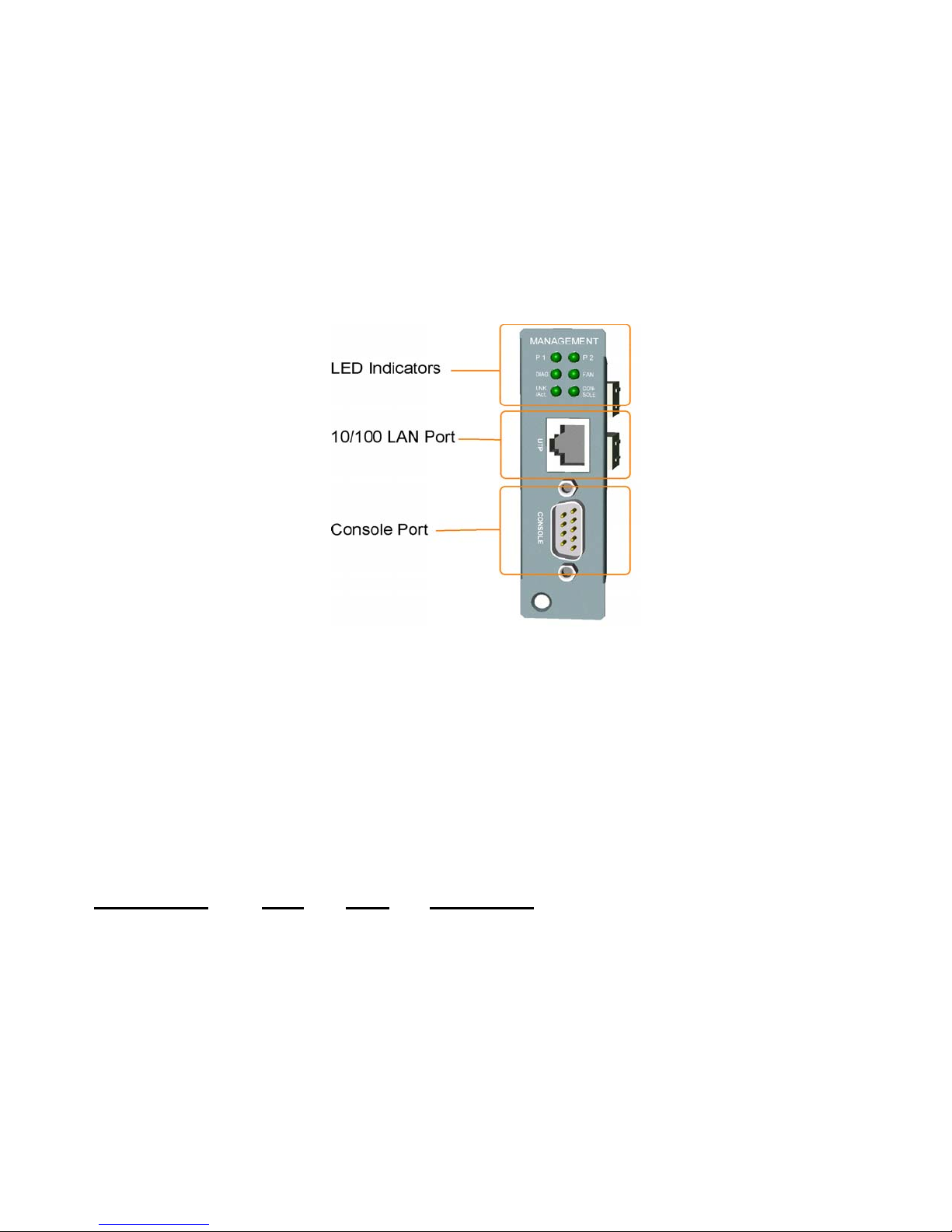
See figure below for major components on the management module panel:
Console Port
This port is a 9-pin male D-sub connector. It serves as an RS-232 DTE port. Refer to Chapter 4 for the console
operation. The pin definitions are:
Pin 2 RXD
Pin 3 TXD
Pin 4 DTR
Pin 5 GND
Pin 6 DSR
UTP Port
This is an auto-negotiation 10/100BASE-TX LAN port and provides a shielded RJ-45 jack with MDI definition.
This port must connect to your TCP/IP network for all in-band management operations.
LED Indicators Color
P1 Green On Power 1 module is ON
P2 Green On Power 2 module is ON
DIAG Green On CPU initialization
FAN Green On Fan failure detected
CONSOLE Green On Rx activities of console port
LNK/ACT Green On LAN port link is active
Green Blink Tx/Rx activities of UTP port
States Interpretation
Off Initialization complete
Off Fan in normal operation
11 www.versitron.com
Page 12
2.2.3 Power Chassis Modules
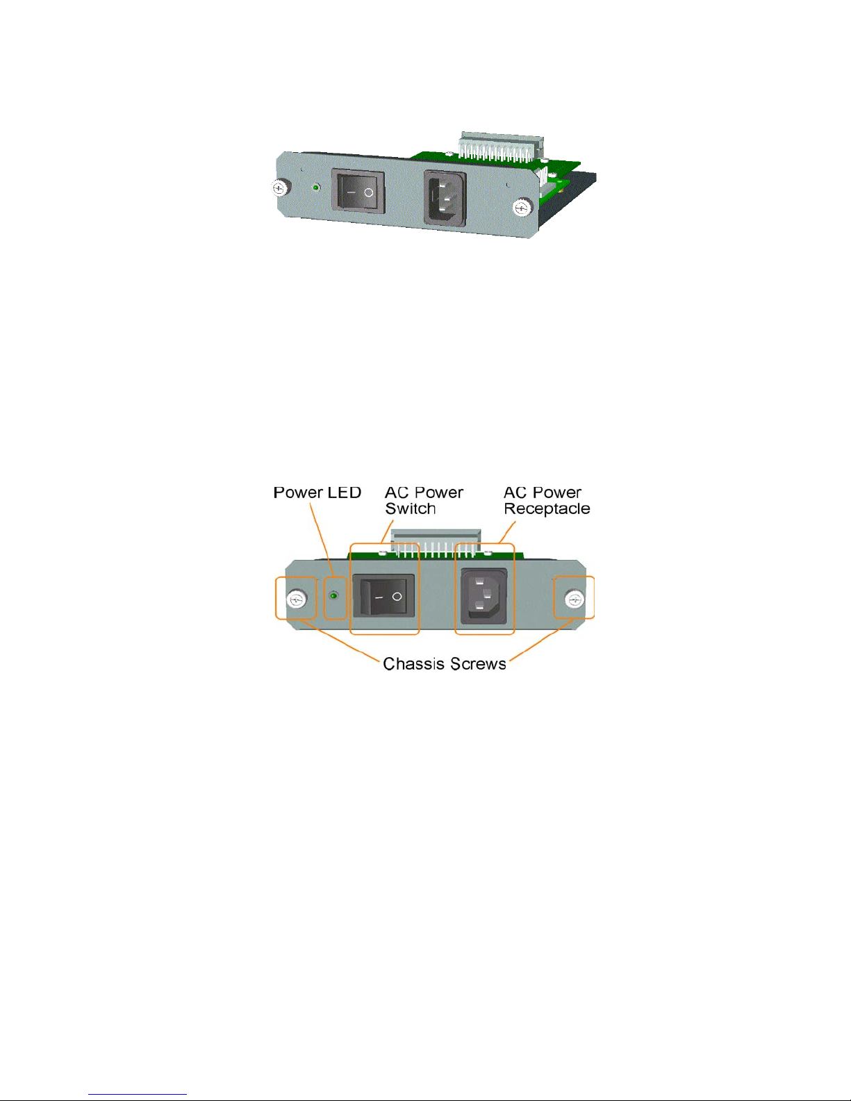
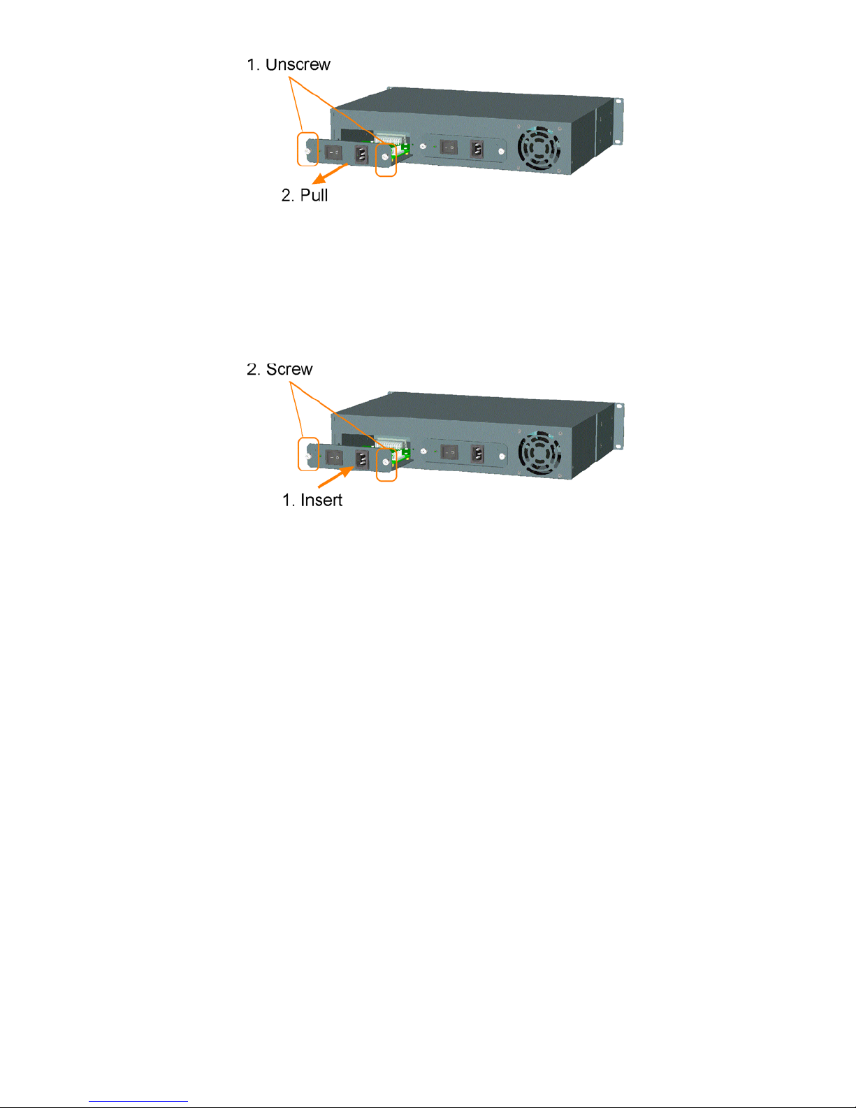
The system power supply is assembled in a plug-in chassis module as shown below:
Each power module is able to supply full power for system operation even when the chassis is fully loaded with
media converters.
AC Power Chassis Specifications
AC power switch System power on/off switch
AC power receptacle IEC320 type receptacle
Input voltage range 90~264VAC
Input frequency 47 ~ 63Hz
Output power 60W
AC power cord IEC320 type power cord
Power status display Green LED
Power Module Removal
The power module is pre-installed in the chassis. The module is designed for easy removal for inspection or
maintenance. However, a well-trained technician should only perform removal of the module.
For safety reasons before removing the power module, make sure:
• The power switch is turned off.
• The power cord is disconnected from the AC power receptacle.
To remove the module, unscrew fastener screws until they are released from the chassis. Hold the handle and pull
the module out from the chassis smoothly. See the following example figure:
12 www.versitron.com
Page 13
Insertion of Power Module
Before inserting the power module into the chassis, make sure:
• The module power switch is turned off.
• The power cord is disconnected from the AC power receptacle.
To insert the power module, hold the handle and push it into the chassis until it is seated in the chassis properly.
Screw the module securely in the chassis unit. See figure below:
The power module is designed to be hot plugged into or unplugged from the system even when another power
module is installed in another power slot and in operation.
13 www.versitron.com
Page 14

2.2.4 Media Converter Slots
The system chassis provides sixteen slots for installing optional slide-in MCs (media converters).
A media converter can be inserted into an available slot or removed from a slot anytime even when the system
unit is powered on. This hot-plug design keeps all existing connections on the other slots running with no
influence.
To insert an MC into a slot, the steps are:
1. Install a bracket, which is provided in the rack chassis package, onto the MC unit as shown below:
2. Remove the slot cover first and insert the MC slowly until it is seated in properly.
3. Screw the bracket onto system chassis securely before making any cable connection.
To remove an MC from slot, the steps are:
1. Disconnect all cable connections on the MC first.
2. Unscrew the MC bracket from system chassis.
3. Hold the bracket and pull it slowly out from the slot.
NOTE: The media converters are designed with hot-plug feature, which allows insertion and removal of
the converters to be performed even when the system is in operation.
14 www.versitron.com
Page 15
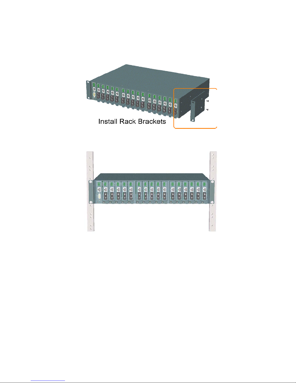
2.3 Rack Mounting
One rack mounting kit is supplied in the product package. It includes two rack mounting brackets and screws for
installing the system unit into a 19-inch rack.
Mount both brackets onto the system unit as shown below:
Install the system unit into a 19-inch rack as shown below:
15 www.versitron.com
Page 16
Chapter 3
Network Management
3.1 Management Functions
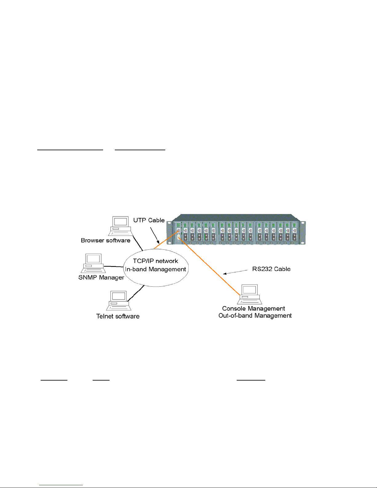
The managed converter rack system series is featured with management functions and can be managed by using
the following methods:
• Direct console connection over an RS-232 cable
• Telnet software over TCP/IP network
• SNMP manager software over TCP/IP network
• Web browser software from Internet or Intranet over TCP/IP network
Management Interface RS-232 / Protocol
Console operation RS-232 console port
Console operation Telnet over TCP/IP
SNMP management SNMP over TCP/IP
Web browser HTTP over TCP/IP
The following figure illustrates a management model diagram:
The system unit is equipped with one management module which serves as a management agent to monitor the
system status and all installed media converter modules. The agent also responds to either in-band management
requests coming from the network or out-of-band requests directly from a connected console.
3.2 Protocols Supported
Protocols Name Reference
IPv4 IP version4 RFC791
TCP Transmission Control Protocol RFC793
UDP User Datagram Protocol RFC768
ICMP Internet Control Message Protocol RFC792
SNMP SNMP agent v1 RFC1157
MIB-II Standard MIB RFC1213
TFTP Trivial File Transfer Protocol RFC1350
TELNET Telnet protocol RFC854
HTTP HTTP server for web management RFC1945
16 www.versitron.com
Page 17
3.3 Setup for Out-of-band (Console) Management
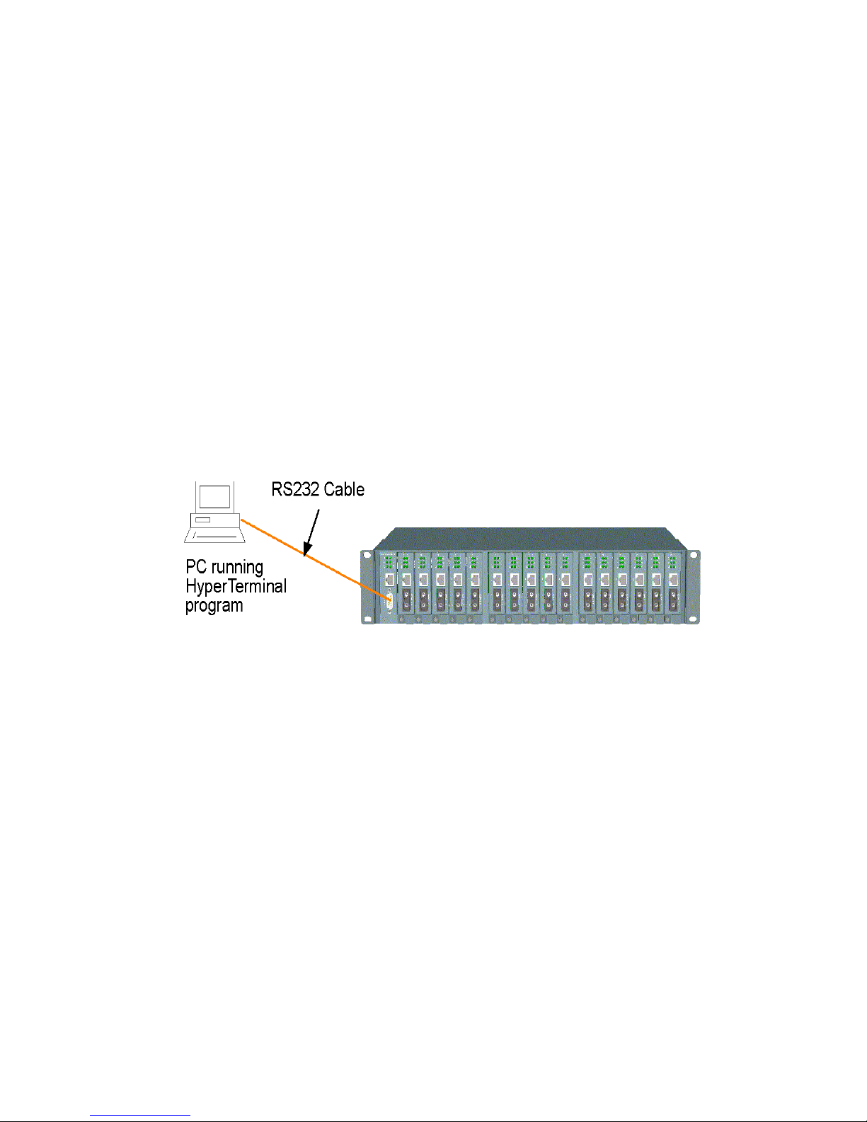
Before doing any in-band management, it is necessary to perform console operations for configuring IP and
SNMP related settings for the first time the system is being installed. The console port is located on the SNMP
module.
Any PC running Windows 95/98/XP/2000/2003 can be used as a console via the COM port. Windows Hyper
Terminal program is an ideal, and the most popular, software for such console terminal operations.
To setup console operation, the steps are:
1. Find a proper RS-232 cable for the connection to a console terminal. If your are using a PC as a Terminal,
make sure the cable pin assignments comply with the following:
Console port 9-pin PC COM port
Pin 2 RXD 3
3 TXD 2
4 DTR 6
5 GND 5
6 DSR 4
2. Connect one end to the console port and connect the other end to the PC COM port.
3. Configure your PC COM port setting to match the RS-232 settings of the console port and start your terminal
software.
Factory default settings of the Console port
Baud rate: 38400, N, 8, 1, 0
Flow control: disabled
4. Turn the system power on.
5. Press <Enter> key several times in your terminal software until a login prompt comes up. It means the
connection is proper.
NOTE: The console port does not support a modem connection.
Refer to Chapter 4 for more information about Console management.
17 www.versitron.com
Page 18
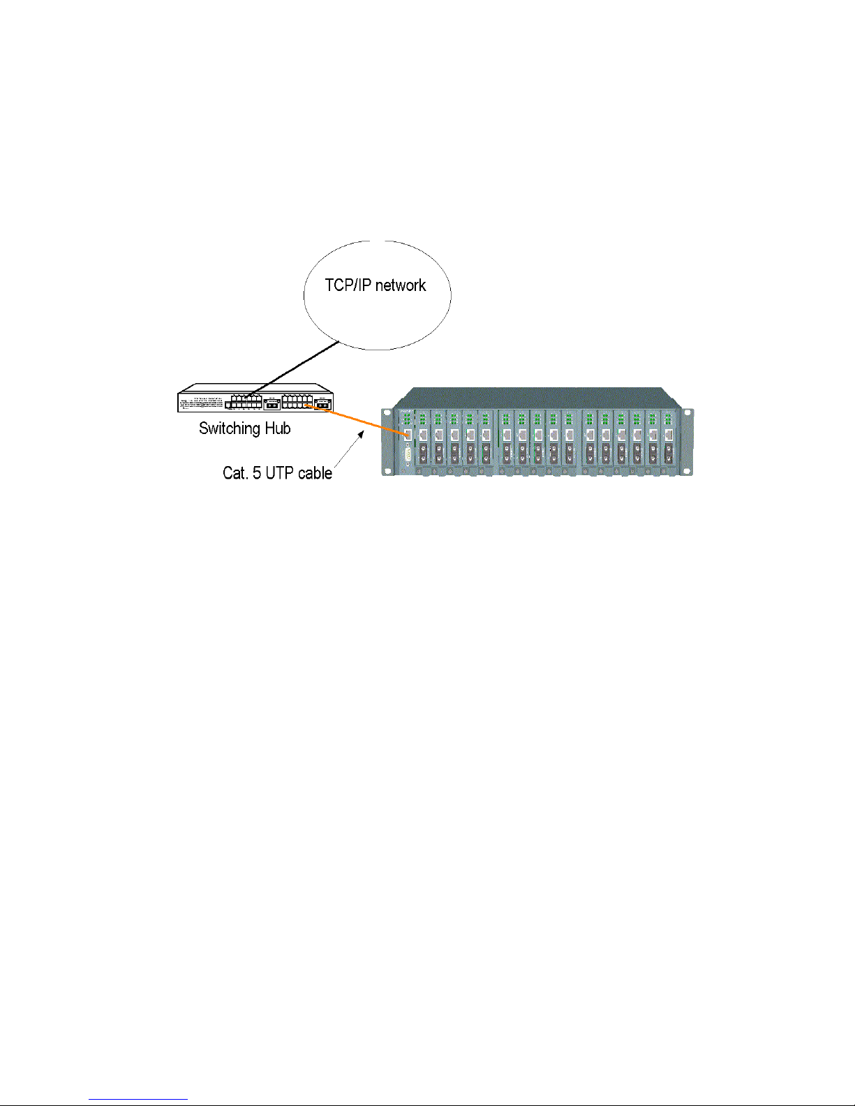
3.4 Setup for In-band Management
To perform an in-band management, it is necessary to connect the system to your TCP/IP network. The steps are:
1. Configure IP and SNMP related settings to the system using direct console management the first time the
system is being installed.
2. Find a proper straight-through Category 5 UTP cable (maximal length 100 meters) for the connection.
3. Connect one end of the UTP cable to the UTP port on the SNMP module and connect the other end to the
device, such as a switching hub, in your TCP/IP network.
4. Start your in-band management operations. For different management methods, refer to:
• Chapter 4 for Telnet management
• Chapter 5 for SNMP management
• Chapter 6 for Web management
18 www.versitron.com
Page 19

Chapter 4
Console and Telnet Operation
Functions supported:
• Set and display IP parameters for the system.
• Set and display SNMP parameters for the SNMP agent function.
• Monitor system power status, power temperature status, system fan status and other system information.
• Monitor installation status of each slot.
• Monitor the configuration and link status of each MC installed.
• Restore default settings for the system
• Change administrator password for access control.
• Update system software.
• Reboot (warm start) the system remotely.
Management Objects Modify Monitor
Password for access control Y System: CPU, memory, flash, software version - Y
Power 1&2 status - Y
System fan status - Y
IP address of the system Y Y
Subnet mask of the system Y Y
Default gateway IP address Y Y
SNMP name Y Y
SNMP location Y Y
SNMP contact Y Y
SNMP community name (up to 4) Y Y
SNMP community access right (up to 4) Y Y
SNMP trap host IP address (up to 3) Y Y
Slot status: module installed or not - Y
MC status: media type, speed, duplex - Y
MC link status of two ports - Y
Remote MC TP link status * - Y
* Remote MC TP link status monitoring is available only when an M727xS in the chassis is connected to a remote
M727xS through a fiber link.
19 www.versitron.com
Page 20

Cold Start
When the power to the system is turned on, the system-start initialization and self-test process starts up. The selftest messages are displayed as follows if a console connection is established successfully:
Power-on Self-test
------------------------------------------------------
$$$ System LOADER Checksum O.K !!!
$$$ System IMAGE Checksum O.K !!!
$$$ Sytem DATA Checksum O.K !!!
$$ Waiting Copy Rom to Sdram
$$$ System Power On Self Test....
$$$ ARM Reg R/W Test Success !!!
$$$ System EEPROM Checksum O.K !!
$$$ Get parameter O.K !!
My Mac Address is xxxxxxxxxxxx
------------------------------------------------------
This chapter describes the detailed console operation. It can be applied to either out-of-band console management
or in-band Telnet management. Both are the same in operation starting from the login prompt.
Direct Console Management
When you see the self-test messages shown on the screen properly, you can press <Enter> to start the console
login operation. Go to the Login Prompt section below.
Telnet Management
Use Telnet software to perform the management operation. The most convenient solution is using the built-in
Telnet function in a Windows 95/98/ or NT PC. Enter into the DOS window and invoke the following Telnet
command to connect to the system unit:
>telnet xxx.xxx.xxx.xxx
The specified xxx.xxx.xxx.xxx is the IP address of the system unit. A welcome message and login prompt are
displayed if the connection is established properly.
Login Prompt
The following figure illustrates the login screen:
------------------------------------------------------
Welcome to Console
login:admin
password:***
------------------------------------------------------
Username: admin
Factory default Password: 123
For security reason, the system supports a function to change the pass- word in setup menu. It is recommended to
change the default password immediately after a successful login.
20 www.versitron.com
Page 21

When logged in successfully, a Setup menu is shown as follows:
------------------------------------------------------
Setup Menu
TCP/IP stack for MCC-16 V1.xx
[0] Print this menu
[1] IP Menu
[2] SNMP Menu
[3] View System status
[4] View Converter Slots Status
[5] Restore Default Value
[6] Security Manager
[7] Update Firmware
[8] Reboot System
[9] Exit
Please Select (0-9)....
Enter Esc to abort....
INET>
------------------------------------------------------
After prompt, type a number followed by [Enter] key for selecting an operation item to perform. See example
below:
INET> n <Enter>
Select [0] to display the main menu again. [Esc] key can be used to abort the operation of any item and get back
to the main menu.
The following sections describe the detailed operation of each item.
21 www.versitron.com
Page 22

4.1 IP Menu
Select [1] from Setup menu to set IP related settings.
------------------------------------------------------
IP Menu
[0] Print this menu
[1] Set IP Address
[2] View IP Status
[3] Exit
Please Select (0-3)
------------------------------------------------------
Set IP Address
---------------------------------------------------------------------------------------------
Enter ESC to abort.
Please Input IP Address(xxx.xxx.xxx.xxx):192.168.0.23
replacing net[0] IP address nnn.nnn.nnn.nnn with 192.168.0.23
Please Input Subnet Mask(xxx.xxx.xxx.xxx):255.255.255.0
replacing subnet mask[0] IP address nnn.nnn.nnn.nnn with 255.255.255.0
Please Input Gateway IP(xxx.xxx.xxx.xxx):192.168.0.1
replacing gateway IP addr[0] nnn.nnn.nnn.nnn with 192.168.0.1
Do you want to Change IP setting ? (Y/N)Y
Please reboot system and use new IP to connection it !
---------------------------------------------------------------------------------------------
IP Address Unique IP address designated to this system
Subnet Mask The subnet mask of the IP address specified above
Gateway The IP address of the default gateway (router)
Note: All current in-band network management connections on the system will be lost if the system IP address is
changed. This change does not affect the operation of the media converter modules in the slots.
View IP Status
---------------------------------------------------------------------------------------------
IP Addr: 192.168.0.23 Submask: 255.255.255.0 Gateway: 192.168.0.1
---------------------------------------------------------------------------------------------
22 www.versitron.com
Page 23

4.2 SNMP Menu
Select [2] from Setup menu to perform SNMP related settings. The following figure illustrates the SNMP menu:
------------------------------------------------------
Snmp Menu
[0] Print this menu
[1] View Snmp Setting
[2] Set Snmp Name
[3] Set Snmp Location
[4] Set Snmp Contact
[5] Set Snmp Community
[6] Set Snmp Trap Manager
[7] Exit
Please Select (0-7 )....
INET>
------------------------------------------------------
SNMP related settings are:
Name Login name for the system (127 characters).
Location Location where the system is installed (127 characters).
Contact Contact person regarding the system (127 characters).
Community SNMP communities to which the system belongs and access rights to the system (R: read
only, W: read/write). Maximum of four communities are supported.
Trap manager IP address of the trap host to which a trap is issued and the trap community to which the
system belongs. A maximum of three trap hosts are supported.
[Esc] key can be used to abort unfinished setting.
4.3 View System Status
Select [3] from Setup menu to view system status. The system status is shown as follows:
---------------------------------------------------------------------------------------------
Power 1 Status: Good , Power 2 Status: Good
FAN status: Good
CPU status:
Cpu Type = ARM7, Flash Size = 512K, Sdram Size = 2M Bytes
Software version 1.xx
---------------------------------------------------------------------------------------------
Power status indicates the status of power modules 1 and 2 in the chassis.
Power Status: Good, Bad
FAN status indicates the status of system cooling fan.
FAN Status: Good, Bad
CPU information and software version are static information for reference.
23 www.versitron.com
Page 24

4.4 View Converter Slots Status
Select [4] from the setup menu for current status of MCs in the chassis. The slot status are shown as follows:
-----------------------------------------------------------------------------------------------------------------------------------------
Slot Port Media Speed Duplex Link Slot Port Media Speed Duplex Link RTP
01 A TX 100M Full Up 01 B FX 100M Full Up Up
02 A TX 100M Full Up 02 B FX 100M Full Up Up
03 A TX 100M Full Up 03 B FX 100M Full Up Up
04 A TX 100M Full Up 04 B FX 100M Full Up Up
05 A TX 100M Full Up 05 B FX 100M Full Up Up
06 A TX 100M Full Up 06 B FX 100M Full Up N/A
07 A TX 100M Full Up 07 B FX 100M Full Up N/A
08 A TX 100M Full Up 08 B FX 100M Full Up N/A
09 A TX 100M Full Up 09 B FX 100M Full Up N/A
10 A TX 100M Full Up 10 B FX 100M Full Up N/A
11 A TX 100M Full Up 11 B FX 100M Full Up N/A
12 A TX 100M Full Up 12 B FX 100M Full Up 13 A TX 100M Full Up 13 B FX 100M Full Up 14 A TX 100M Full Up 14 B FX 100M Full Up 15 A TX 100M Full Up 15 B FX 100M Full Up 16 A TX 100M Full Up 16 B FX 100M Full Up -
-----------------------------------------------------------------------------------------------------------------------------------------
The slot status definitions are:
Column States
Slot 01-16 Slot position in the chassis
Interpretation
Slot #1 - slot #16 are for MC
Port N/A No module is installed in slot
A Upper port of the module in slot
B Lower port of the module in slot
Media N/A No MC is installed in slot.
TX 10BASE-T, 10/100BASE-TX port type
FX 100BASE-FX port type
Speed N/A No MC is installed in slot
10M 10Mbps
100M 100Mbps
Duplex N/A No MC is installed in slot
Full Full duplex
Half Half duplex
Link N/A No MC is installed in slot
Up Link up
Down Link down
RTP * N/A Status not available
Up Remote MC TP link up
---- MC in slot is not M727xS
• RTP: Remote MC TP link status monitoring is available only when M727xS in the chassis is connected to a
remote M727xS through a fiber link.
24 www.versitron.com
Page 25

4.5 Restore Default Values
Select [5] from Setup menu to restore factory default settings.
Factory default settings are:
IP Address 192.168.0.2
Subnet Mask 255.255.255.0
Default Gateway 192.168.0.1
User Name admin
Password 123
Name (null)
Location (null)
Contact (null)
SNMPCommunities:
No.1 Community name public
No.1 Access right Read only
No.2 Community name (null)
No.2 Access right (N/A)
No.3 Community name (null)
No.3 Access right (N/A)
No.4 Community name (null)
No.4 Access right (N/A)
SNMP Trap Managers:
No.1 Trap manager IP (null)
No.1 Community name (null)
No.2 Trap manager IP (null)
No.2 Community name (null)
No.3 Trap manager IP (null)
No.3 Community name (null)
25 www.versitron.com
Page 26

4.6 Security Manager
Select [6] from Setup menu to change login user name and password.
The steps are:
Display current user name
------------------------------------------------------
Current username: admin
Current password: ********
Press Esc to abort ....
------------------------------------------------------
Change user name and password
------------------------------------------------------
Change username [admin]: xxxxxx
Enter password (1-8): ********
Confirm password: ********
Password updating .......
Password updated.
INET>
------------------------------------------------------
26 www.versitron.com
Page 27
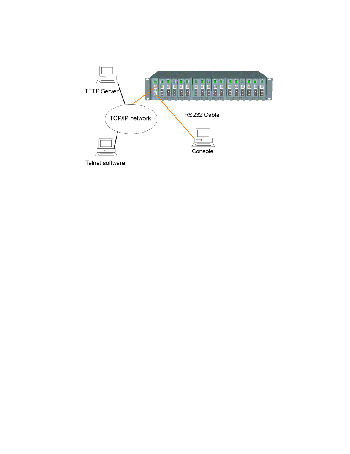
4.7 Update Firmware
Select [7] from Setup menu to perform firmware (system software) up- grade via TFTP protocol. Before doing
TFTP operation, one TFTP server is required and installed in the network to where this system connects and new
firmware file image.bin must be placed in the TFTP server.
The following information is required for TFTP operations:
TFTP Server IP Address: IP address of the TFTP server where the firmware image.bin is downloaded from.
The steps are:
Specify TFTP server IP address
---------------------------------------------------------------------------------------------
Enter ESC to abort.
Please Input TFTP Server IP Address (xxx.xxx.xxx.xxx):192.168.0.88
TFTP Server: 192.168.0.88
---------------------------------------------------------------------------------------------
Confirm to start downloading
---------------------------------------------------------------------------------------------
Do you want to start download new image ? (Y/N) Y
Download image and please wait........
---------------------------------------------------------------------------------------------
Confirm to update system flash memory
---------------------------------------------------------------------------------------------
Download new image complete, do you want to update flash ? (Y/N) Y
Update flash and please wait ....
Update flash complete and please reboot system !
INET>
---------------------------------------------------------------------------------------------
4.8 Reboot System
Select [8] from Setup menu to reboot the system. This reboot function allows you to perform a warm start to the
system.
---------------------------------------------------------------------------------------------
Do you want to reboot system? (Y/N) Y
---------------------------------------------------------------------------------------------
27 www.versitron.com
Page 28
Chapter 5
SNMP Management
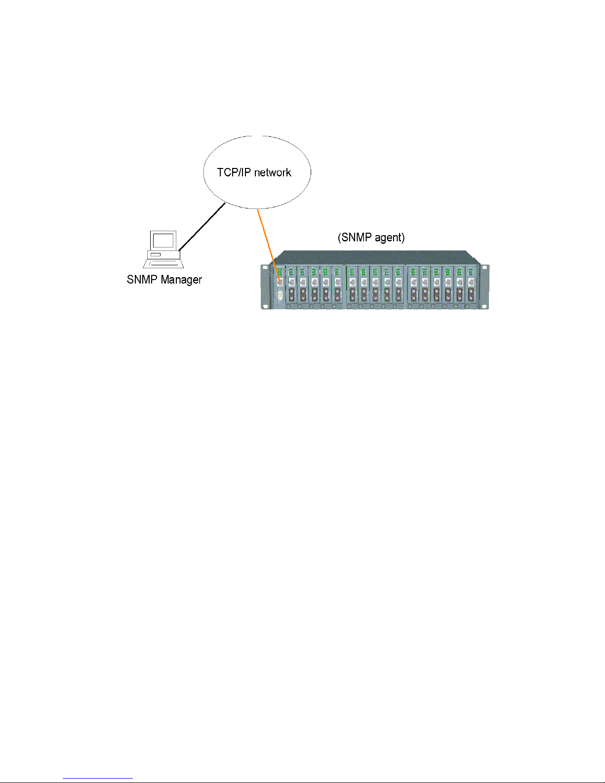
SNMP management is performed at a network management station running SNMP network management
application manager software with graphical user interface. The following figure illustrates an example model:
The system unit serves as an SNMP agent and provides the capabilities that allows network administrators via
SNMP protocol to set parameters and view system status and media converter status defined in the standard MIBII and private MIB.
5.1 Configuring SNMP Settings via Console Operation
Before performing SNMP operation, proper SNMP settings must be configured in the system unit. The SNMP
related settings are:
Name Login name to identify a specific system unit
Location Location where the system is installed
Contact Contact person regarding the system
Community SNMP communities to which the system belongs and access rights to the system (read
only or read/write)
Trap hosts IP addresses of trap hosts to which a trap is issued and the trap community to which the
system belongs
Up to four SNMP communities and up to three trap hosts are supported by the system SNMP agent.
These settings can be configured through console or telnet operation. Refer to Chapter 4 for more information.
28 www.versitron.com
Page 29

5.2 SNMP Private MIB
Use the SNMP management application software to compile the MIB file first before performing any
management operation. In addition to standard MIB-II (RFC1213), the system supports private MIB as below:
Private MIB Objects Get
ssPowerStatus(kti.30.1.1) Y Power 1&2 status
ssFanStatus(kti.30.1.2) Y System fan status
cputype(kti.30.2.1) Y ARM7
flashrom(kti.30.2.2) Y 512KB
memsize(kti.30.2.3) Y 2MB
softwarever(kti.30.2.4) Y 1.xx
mibFileVer(kti.30.2.5) Y 1.xx
portNumber(kti.30.3.1) Y Total number of slots
portTable(kti.30.3.2) portEntry(1) slotIndex(1) Y Slot ID 1 – 16
slotIndexDescription(2) Y Slot1 - Slot16
slotModuleDescription(3) Y
slotModuleType(4) Y
sotModuleStatus_PortA_Media(5) Y Port A media type
slotModuleStatus_PortA_LineSpeed(6) Y Port A line Speed
slotModuleStatus_PortA_Duplex(7) Y Port A duplex mode
slotModuleStatus_PortA_LinkStatus(8) Y Port A Link status
slotModuleStatus_PortB_Media(9) Y Port B media type
slotModuleStatus_PortB_LineSpeed(10) Y Port B line speed
slotModuleStatus_PortB_Duplex(11) Y Port B duplex mode
slotModuleStatus_PortB_LinkStatus(12) Y Port B link status
slotModuleStatus_RTP_LinkStatus(13) * Y Remote MC link status
Remark
* RTP_LinkStatus : TP port link status of the connected remote MC
Note: Port A is the upper port of the MC; Port B is the lower port of the MC
Refer to MIB file, KC1300-Vx.xx.mib for the details. This file can be used for MIB compiler.
29 www.versitron.com
Page 30

5.3 SNMP Traps
The system also supports the following SNMP traps. When the trap event occurs, the SNMP agent will generate a
trap notification to the SNMP management station.
Trap Name Event of Trap Generated
Cold Start The system is powered on and complete initialization
Authentication failure SNMP community authentication failure
Power status Any power failure of Power1and Power2
Power status Any power recovery of Power1 and Power2
Fan status Fan failure
Fan status Fan recovery
Slot # Port A link Slot # MC Port A link down or up
Slot # Port A link Slot # MC Port A link recovery
Slot # Port B link Slot # MC Port B link down or up
Slot # Port B link Slot # MC Port B link recovery
Slot # RTP link Slot # remote MC TP link change
The binding information together with a trap is:
Trap Name Var B i n d
Cold Start sysDescr, ie KC-1300
Authentication failure sysDescr, ie, KC-1300
Power Status Power status for Power1 and Power2
Fan Status Fan status
Slot # Port A link Slot description and Port A link status
Slot # Port B link Slot description and Port B link status
Slot # RTP link Slot description and remote MC TP link status
Remark:
1. The slot # can be slot 1 up to slot 16.
2. Port A: the upper port of the MC installed in slot.
3. Port B: the lower port of the MC installed in slot.
30 www.versitron.com
Page 31

Chapter 6
Web Management
The system features an http server for serving management requests coming from any web browser software over
the internet or intranet network.
Web Browser
Compatible web browser software with JAVA support
Microsoft Internet Explorer 4.0 or later
Netscape Communicator 4.x or later
Set IP Address for the System Unit
Before the system can be managed from a web browser software, make sure a unique IP address is configured to
the system. Refer to Chapter 4 for how to set IP address.
6.1 Starting Browser Software and Making Connection
Start your browser software and enter the IP address of the system unit to which you want to connect. The IP
address is used as a URL for the browser software to search the device.
URL: http://xxx.xxx.xxx.xxx/
Factory default IP address: 192.168.0.2
31 www.versitron.com
Page 32
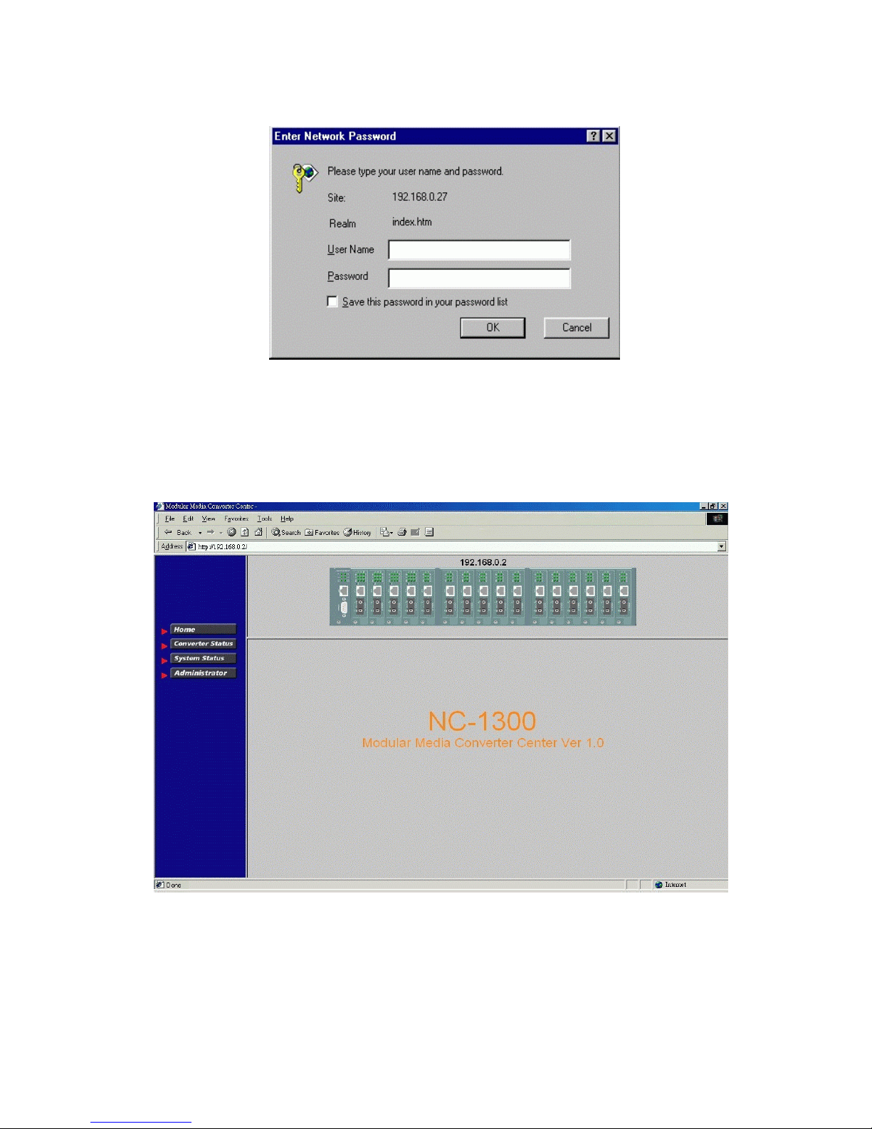
6.2 Login to the System Unit
When browser software connects to the system unit successfully, a Login screen is provided for you to login to the
device as follows:
Login
Username: Admin
Factory default Password: 123
The following screen is displayed when a successful login is performed.
In addition to the device image, the screen supports the following functions on the right side:
1. Home: home page and device image
2. Converter Status: view all slot status
3. System Status: view system related status
4. Administrator: other management functions
32 www.versitron.com
Page 33
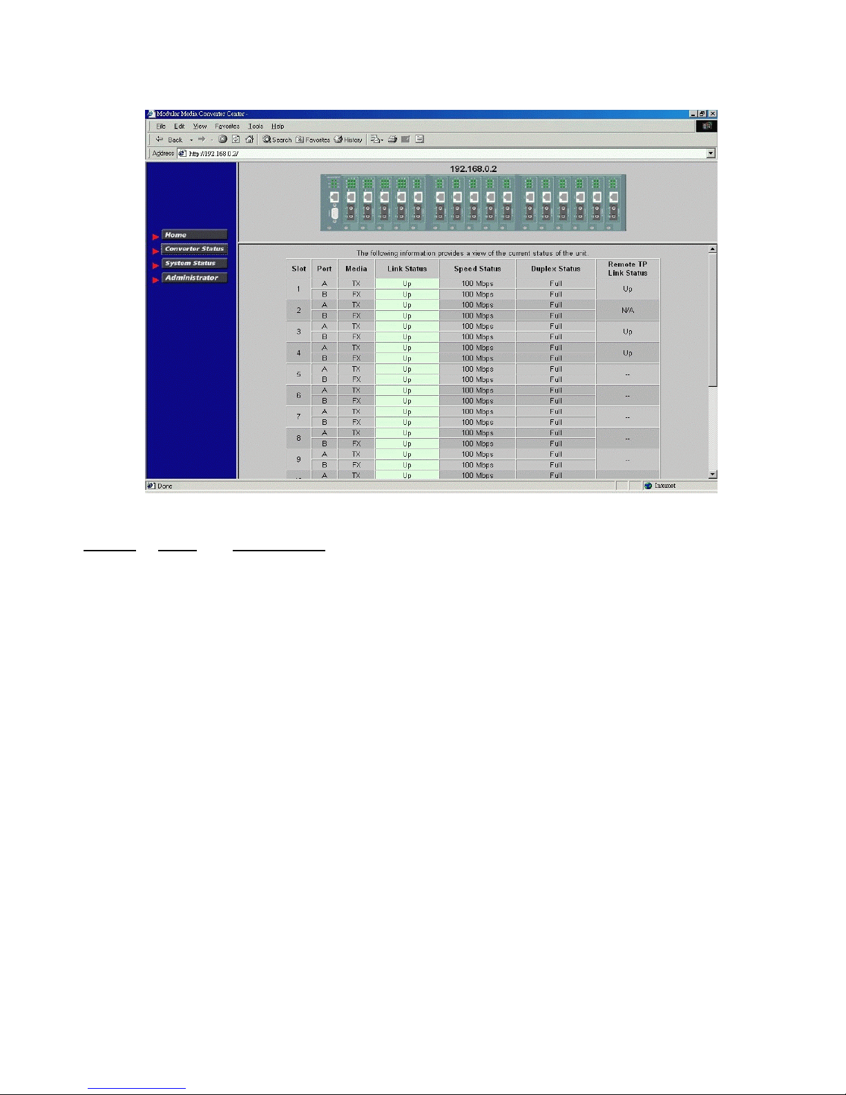
6.3 Converter Status
Click [Converter Status] to view all slot status in a table format.
The information includes:
Column States
Slot 01-16 Slot position in the system
Port A Upper port of the module in the slot
B Lower port of the module in the slot
Media TX Twisted-pair port type
FX Optic fiber port type
Link Green Link up
Red Link down
Speed 10Mbps 10BASE-T or 10BASE-FL
100Mbps 100BASE-TX or 100BASE-FX
1000Mbps 1000BASE-T or 1000BASE-SX/LX
Duplex Full Full duplex
Half Half duplex
Interpretation
Slot #1 - slot #16 are for MC installation
RTP link Green Remote MC TP link up *
Red Remote MC TP link status not available
* RTP: Remote MC TP link status monitoring is available only when M727XS in the rack is connected to a
remote M727XS through a fiber link.
33 www.versitron.com
Page 34
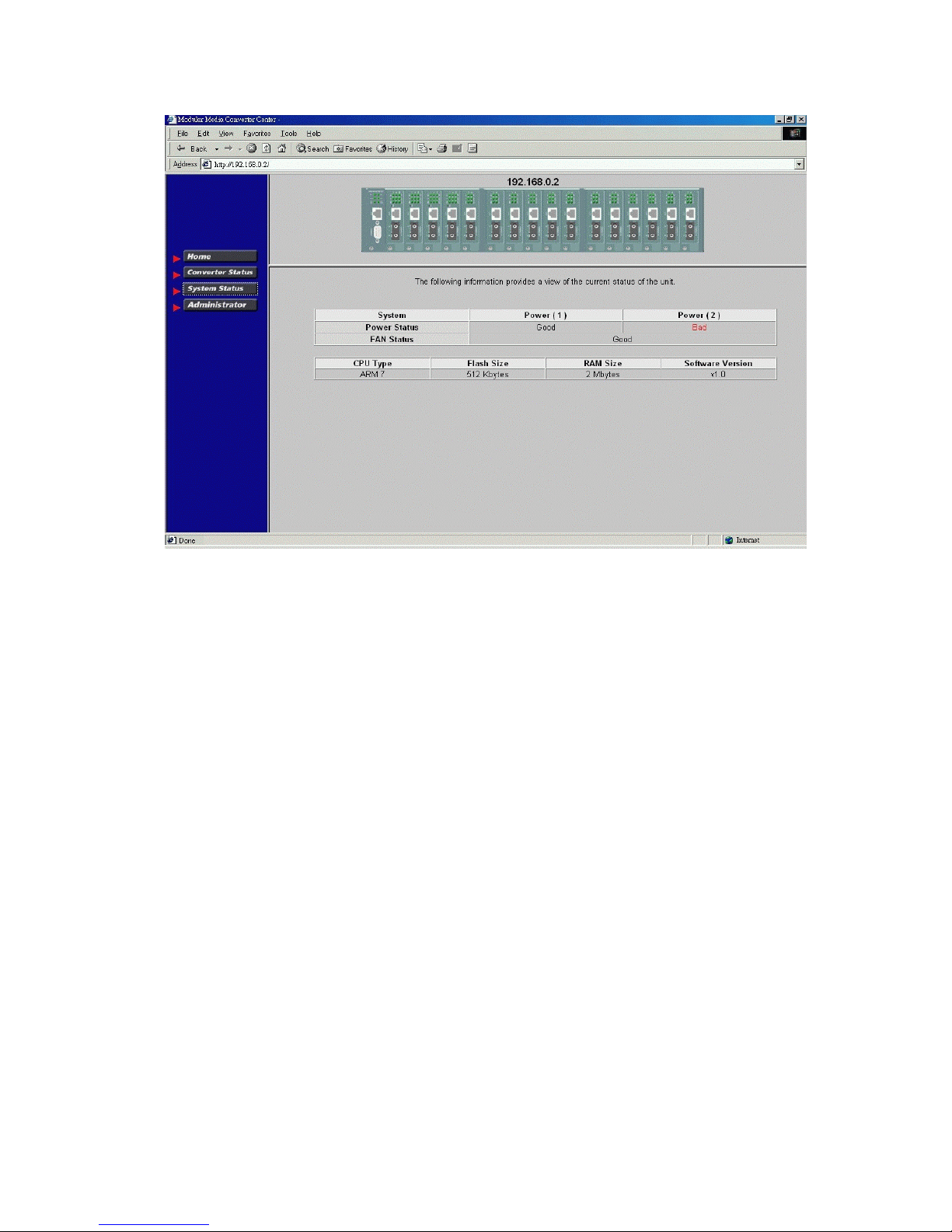
6.4 System Status
Click [System Status] to view system related status in a table format. The information includes:
Power Status : System power 1&2 chassis condition
FAN Status : System fan status
CPU type : CPU model equipped in management module
RAM size : Memory size equipped in management module
Flash size : Flash memory equipped in management module
Software version : Software version built in management module
34 www.versitron.com
Page 35
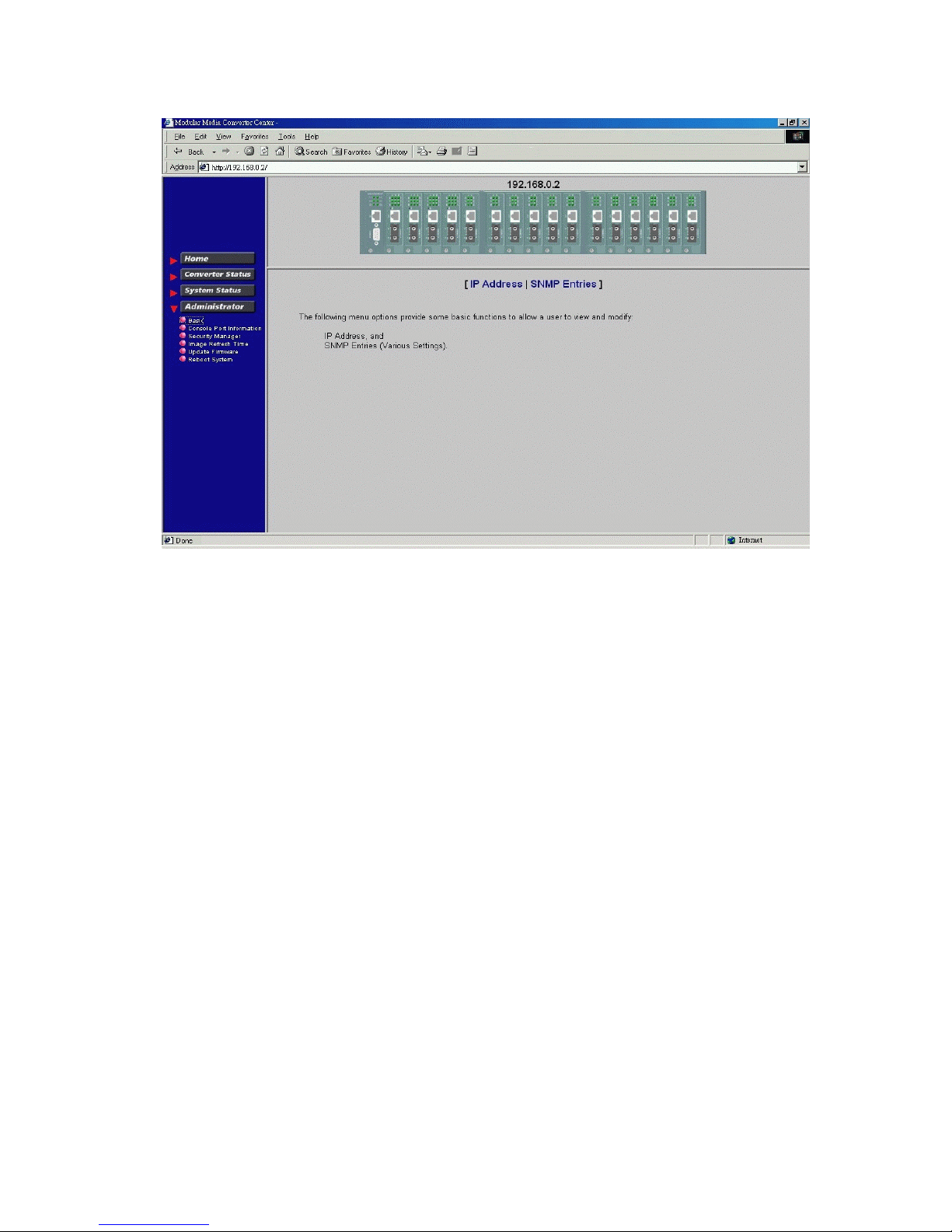
6.5 Administrator Menu
Click [Administrator] to show administrator menu. The menu includes the following options:
1. Basic: Set / View IP and SNMP related settings
2. Console Port Information: View RS-232 console configuration
3. Security Manager: Change login user name and password
4. Image Refresh Time: Set refresh time interval of the image
5. Update Firmware: Update the software built in SNMP module
6. Reboot System: Reboot the system remotely
Refer to the following sections for the details.
35 www.versitron.com
Page 36
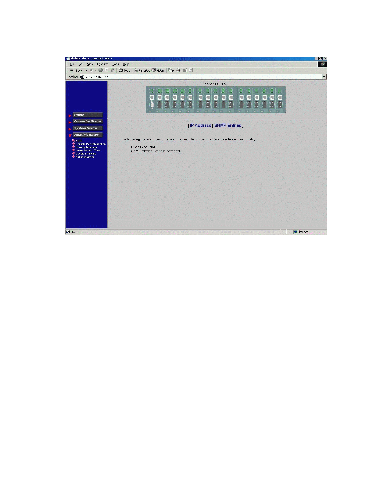
6.5.1 Basic
Click [Basic] to perform IP setting and SNMP settings.
IP setting and SNMP setting are described in the following sections respectively.
36 www.versitron.com
Page 37
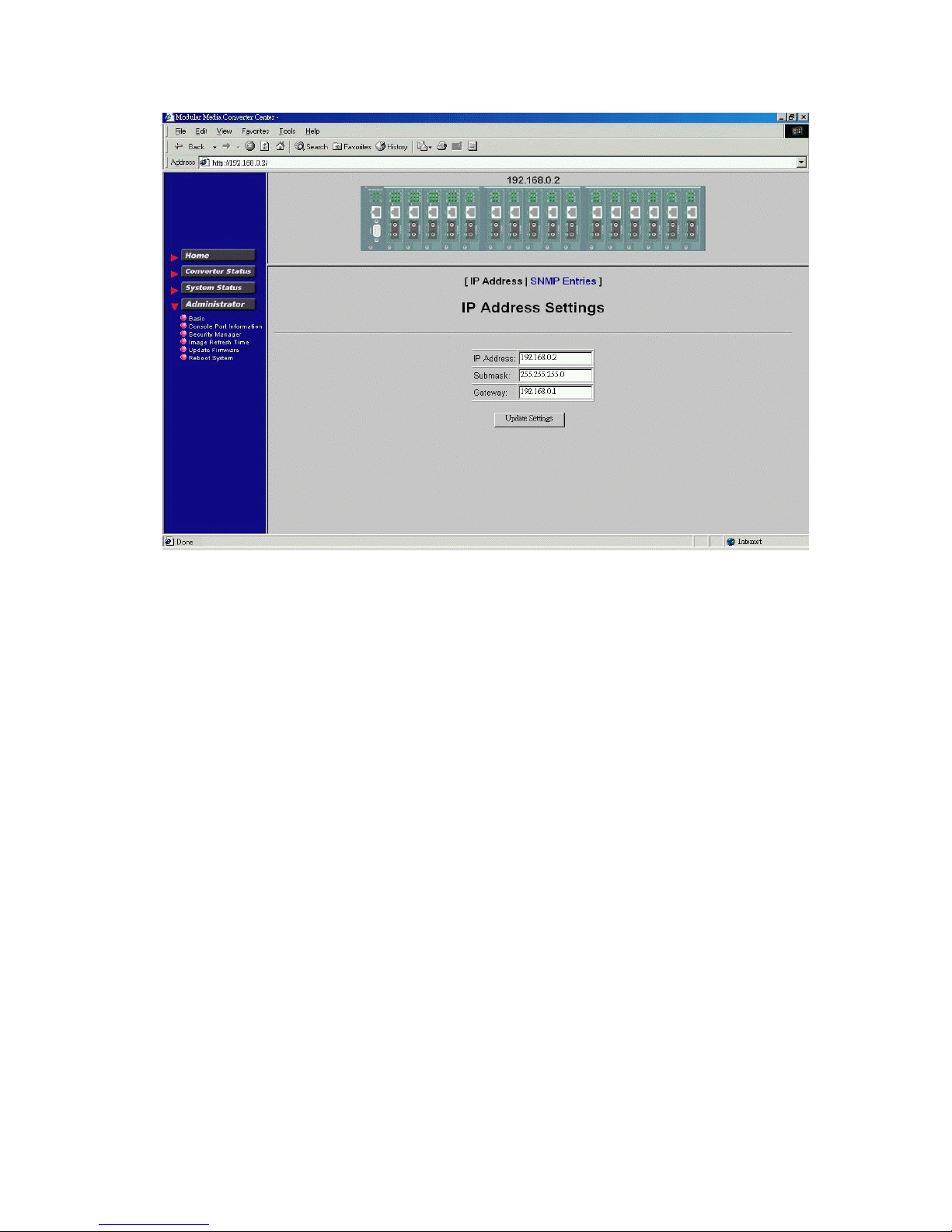
Click [IP Address] button to set IP settings.
IP settings include:
IP Address : Unique IP address designated to this system
Subnet Mask : The subnet mask of the IP address specified above
Gateway : The IP address of the default gateway (router)
Click [Update Settings] to make new settings effective. However, a new IP address change will make your
current connection invalid. Restart your web link with new IP address to connect the system.
37 www.versitron.com
Page 38
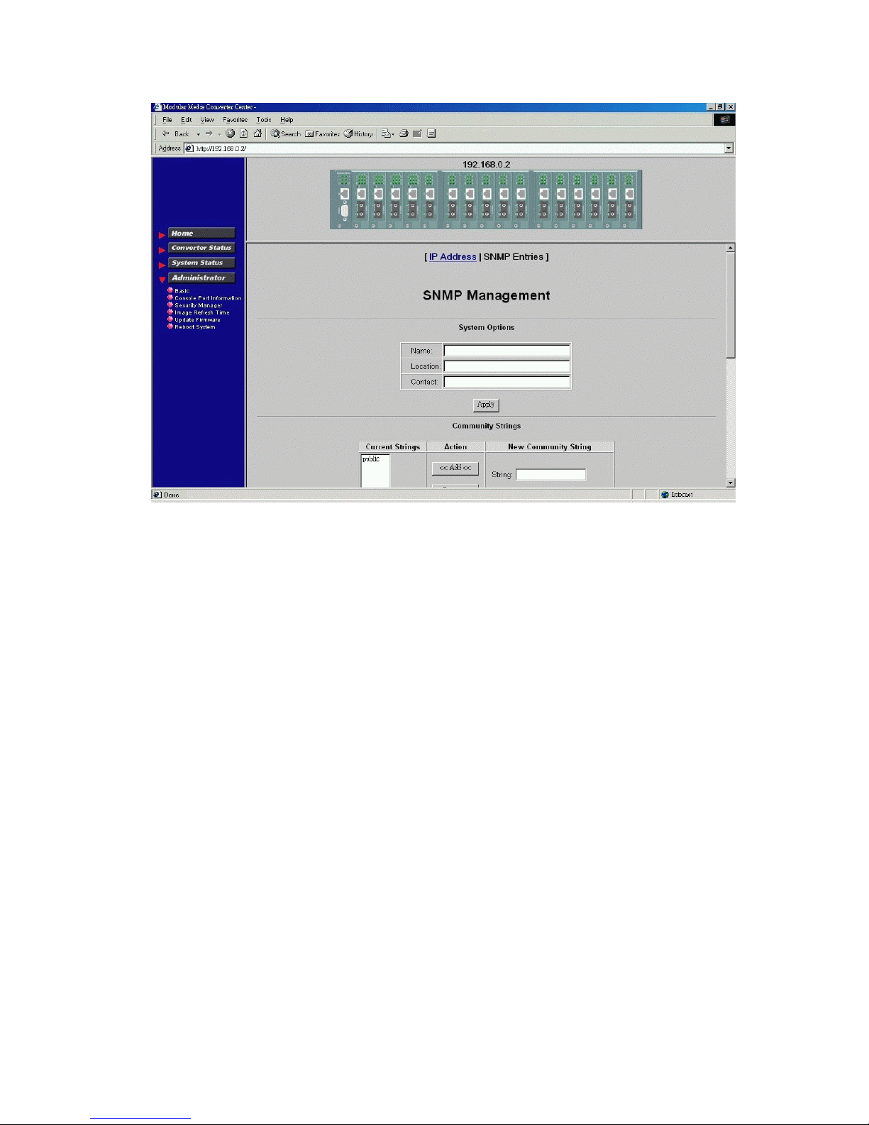
Click [SNMP Entries] button to set SNMP settings.
SNMP Entries - System options
SNMP related settings are:
Name : Login name for the system
Location : Location where the system is installed
Contact : Contact person regarding the system
[Apply] : Click button to make the settings effective
38 www.versitron.com
Page 39
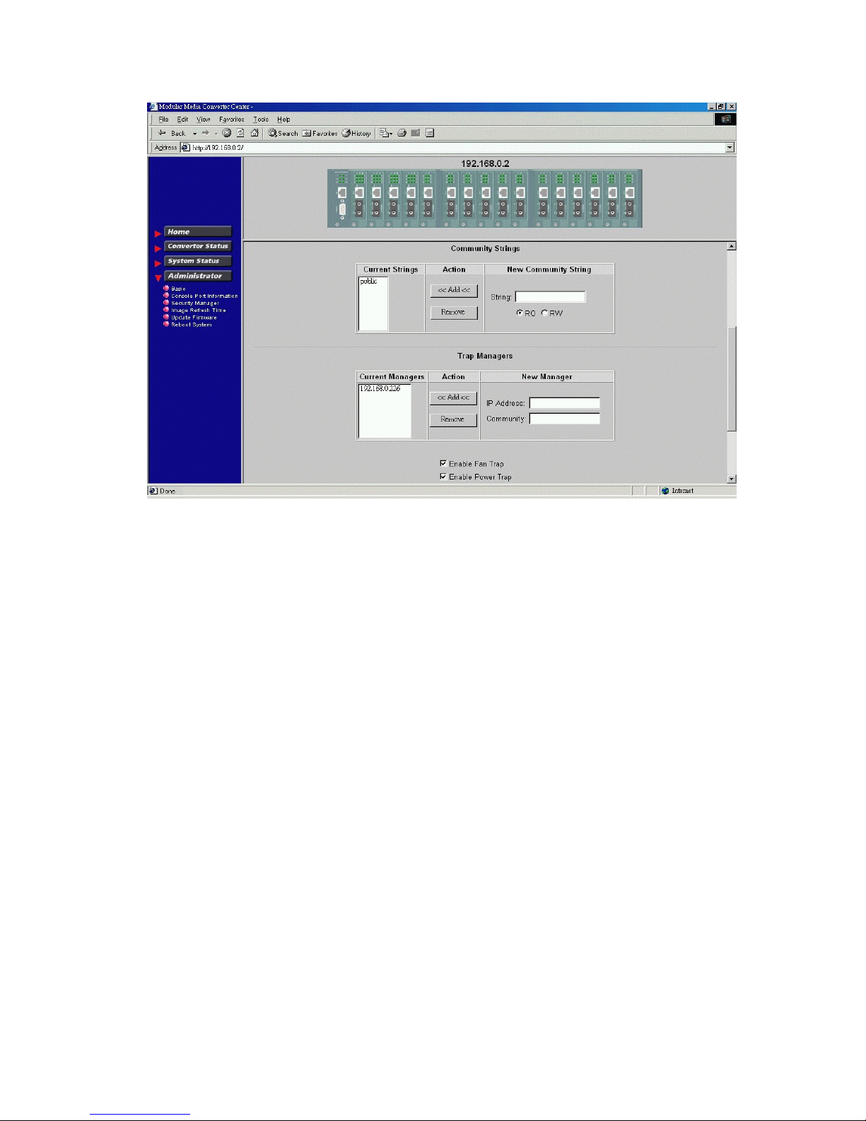
SNMP Entries - Community Strings
One community contains two settings:
Community name : SNMP communities to which the system belongs
Access right : Access rights associated with the community name
Click [Add] button to add one new community into the community list.
Click [Remove] button to remove one community from the community list.
Up to four entries are supported in the community list.
39 www.versitron.com
Page 40
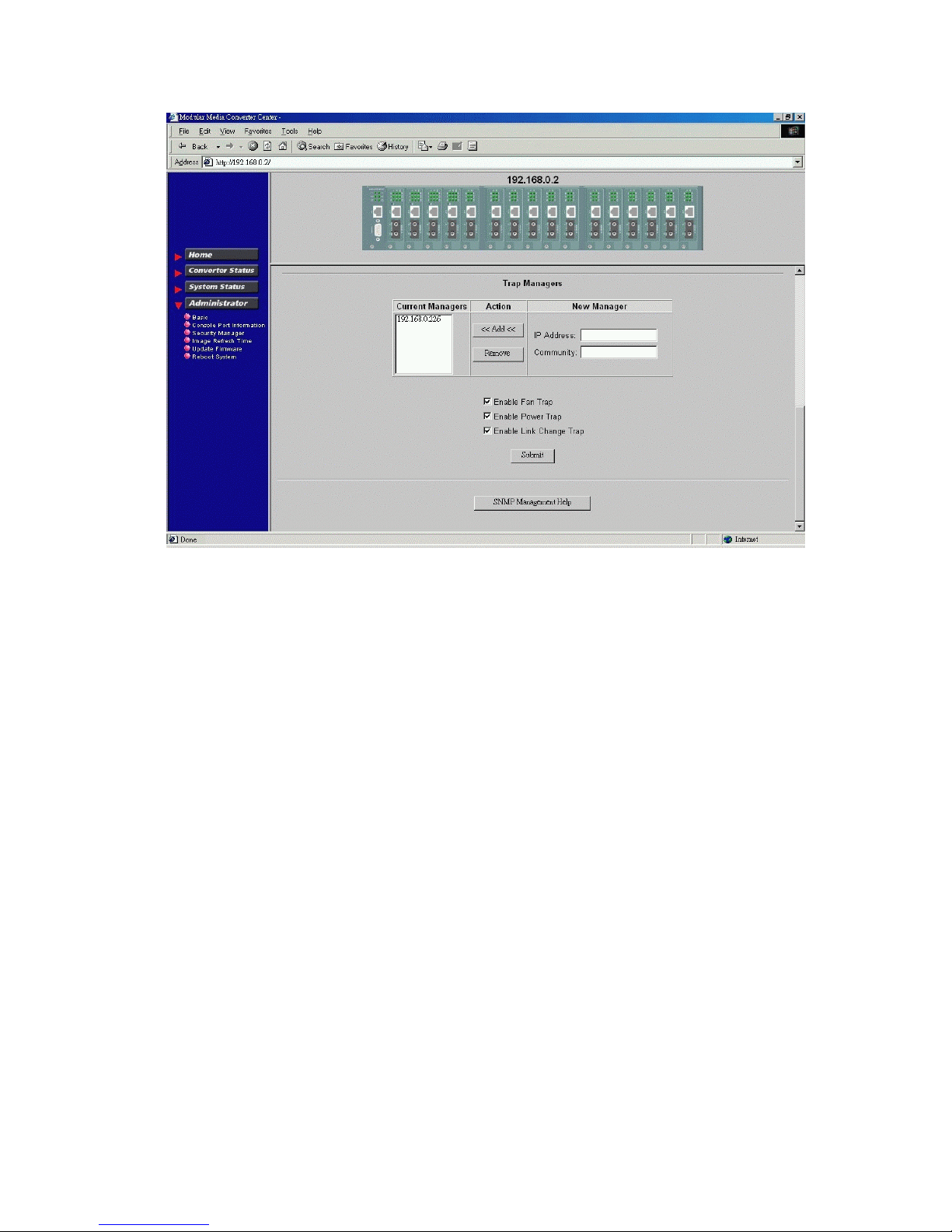
SNMP Entries - Trap Managers
One Trap Manager contains two settings:
IP Address : IP address of the trap host to which a trap is issued
Community : The trap community to which the system belongs
Enable Fan Trap : Enable trap for fan failure events
Enable Power Trap : Enable trap for power failure events
Enable Link Change Trap : Enable trap for any link change events
Click [Add] to add one trap manager into the manager list.
Click [Remove] to remove one trap manager from the manager list.
40 www.versitron.com
Page 41

6.5.2 Console Port Information
This screen displays the configuration of the RS-232 console port.
41 www.versitron.com
Page 42
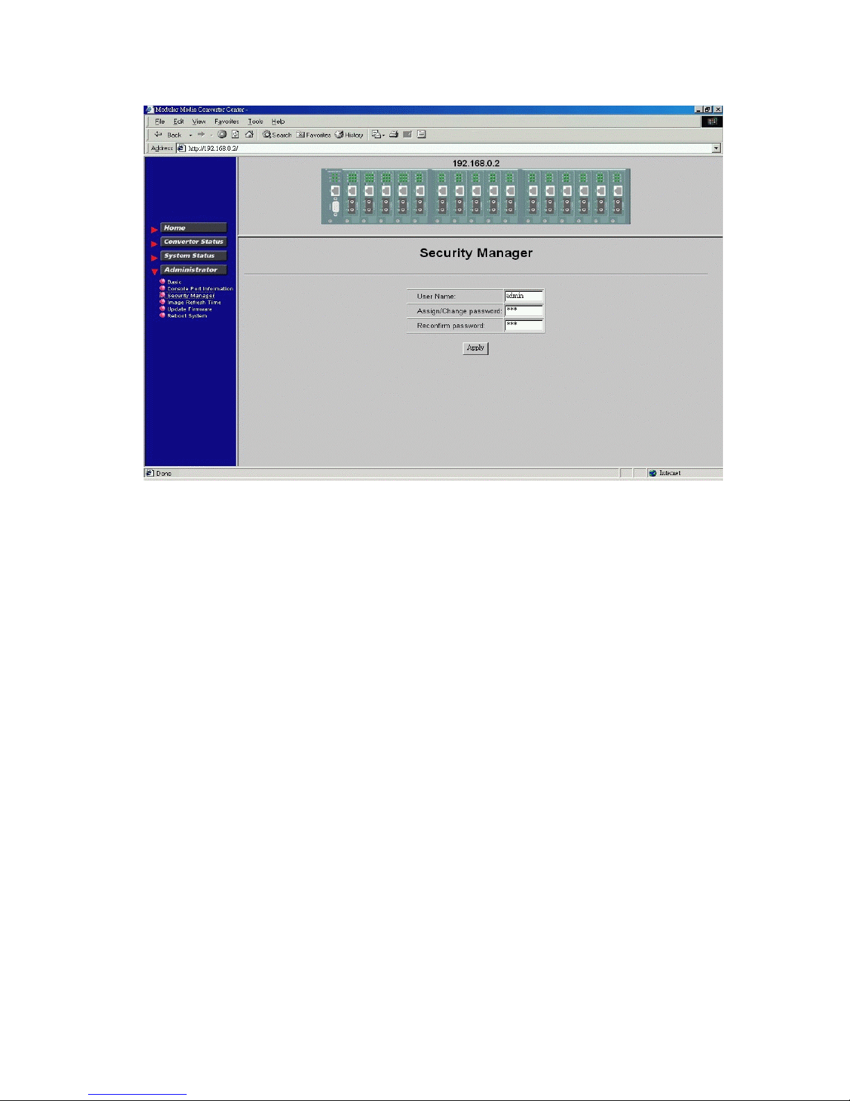
6.5.3 Security Manager
Security Manager allows you to change login user name and password. Click [Apply] to make the changes
effective.
42 www.versitron.com
Page 43
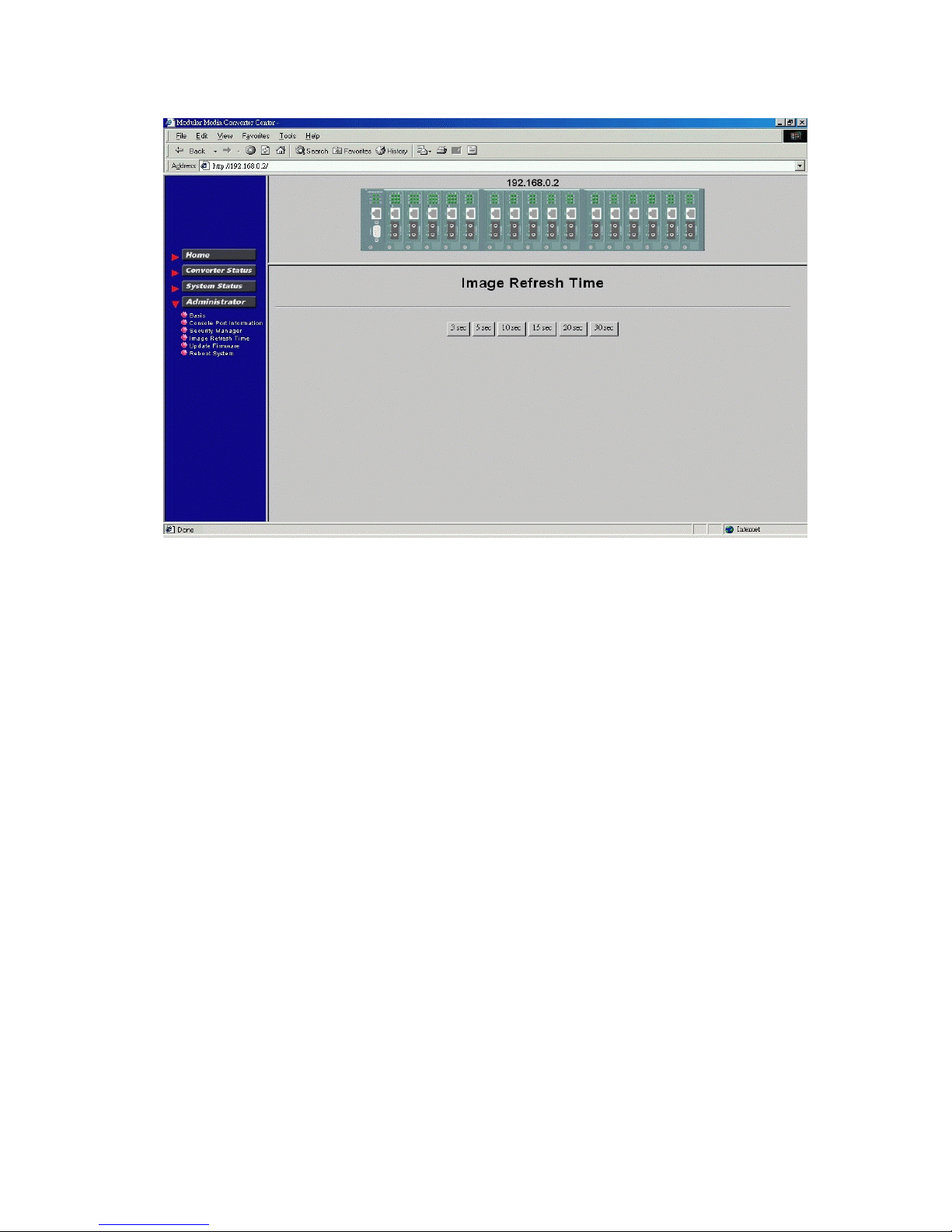
6.5.4 Image Refresh Time
The system image is updated periodically to present the latest status. The default time interval of refreshing the
image is 20 seconds. It can be changed by clicking any of the time buttons displayed. This is a run time setting
and not a permanent setting.
43 www.versitron.com
Page 44
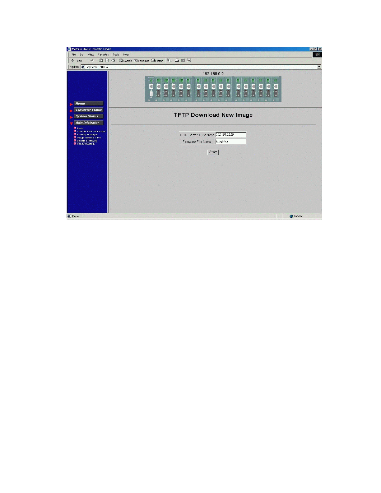
6.5.5 Update Firmware
[Update Firmware] allows you to perform firmware (system software) upgrade via TFTP protocol. Before doing
TFTP operation, one TFTP server is required and installed in the network to where this system connects and the
new firmware file image.bin must be placed in the TFTP server.
Set IP address for the TFTP server from where the firmware image is to be downloaded. Specify the file name as
Image.bin.
Click [Apply] to start the file transfer operation.
44 www.versitron.com
Page 45
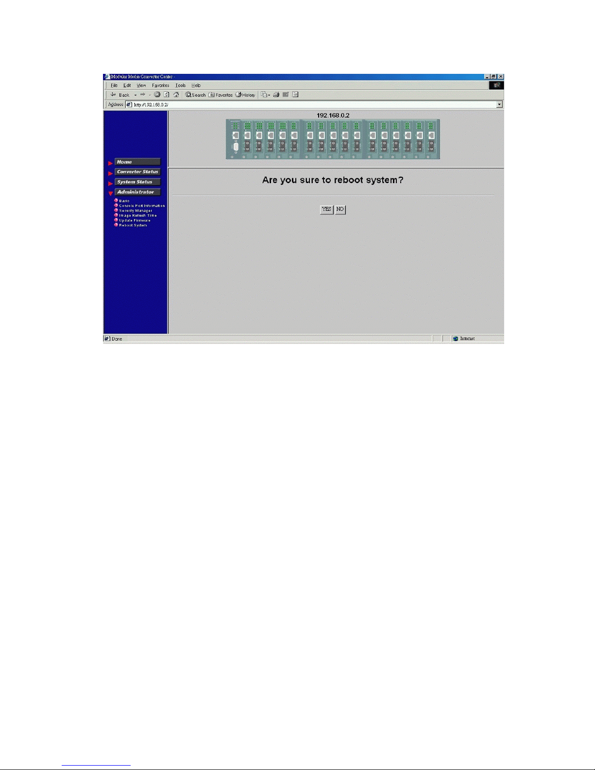
6.5.6 Reboot System
[Reboot System] allows you to reboot the system unit remotely. Starting this command will make your current
http connection lost. You must rebuild the connection to perform any management operations to the unit.
45 www.versitron.com
Page 46
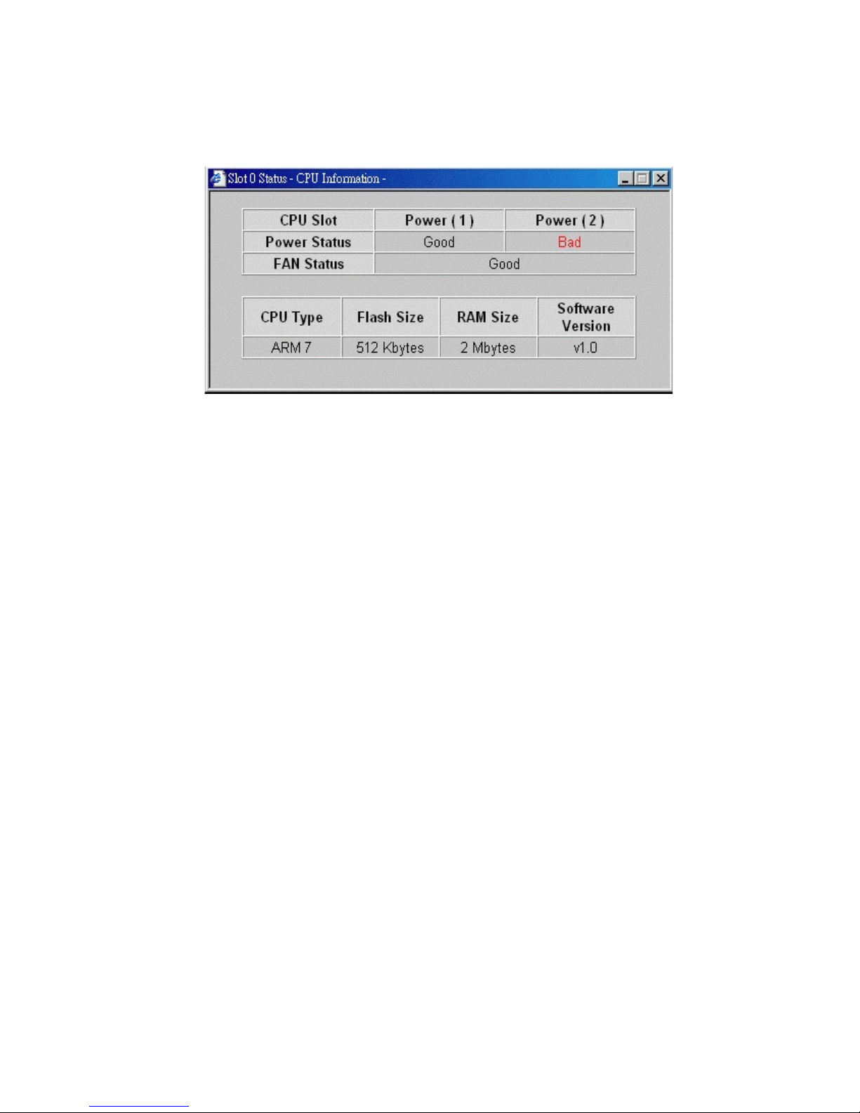
6.6 Slot Icon Operations
In addition to the menu supported, you may click the following image icons to show specific status.
Click slot 0 on the system image shown on the screen
Power Status : System power 1&2 condition
Fan Status : System fan status
CPU type : CPU model equipped in management module
RAM size : Memory size equipped in management module
Flash size : Flash memory equipped in management module
Software version : Software version built in management module
46 www.versitron.com
Page 47
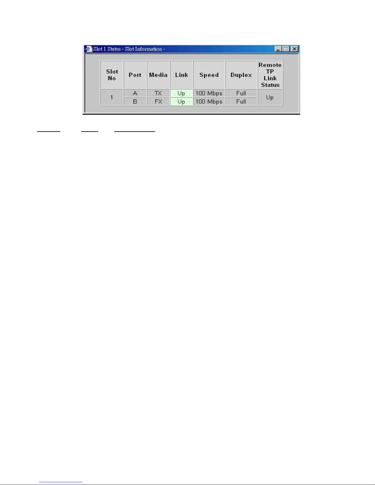
Click any one slot in slot 1 to slot 18 to view one specific slot status. The following figure illustrates slot 9 status:
Column States Interpretation
Slot 1-16 Slot position in the system
Slot #1 - slot #16 are for MC
Port A Upper port of the MC in the slot
B Lower port of the MC in the slot
Media TX Twisted-pair port type
FX Optic fiber port type
Link Green Up - Link up
Red Down - Link down
Speed 10Mbps 10BASE-T or 10BASE-FL
100Mbps 100BASE-TX or 100BASE-FX
1000Mbps 1000BASE-T or 1000BASE-SX/LX
Duplex Full Full duplex
Half Half duplex
RTP Link Green Up - Remote MC TP link up
Red N/A - Remote MC TP link status not available
* RTP Link: Remote MC TP link status monitoring is available only when M727XS in the rack is connected to a
remote M727XS through fiber link.
47 www.versitron.com
 Loading...