

Page 1
YOUR COPPER-TO-FIBER CONNECTION
M7250
Gigabit Ethernet
1000BASE-T TO 1000BASE-X
MEDIA CONVERTERS
Installation Guide
General
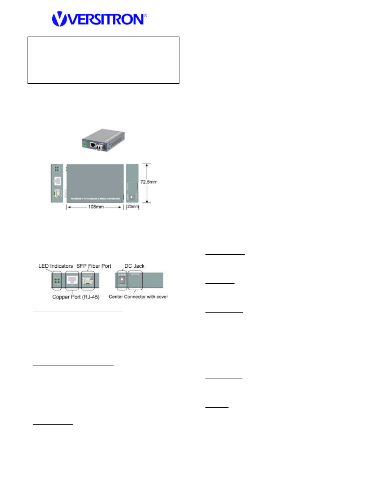
The 1000BASE- T to 1000BASE-X media converter series
provides 1000Mbps Gigabit Ethernet copper-to -fiber media
conversion, allowing for 1000Base- T-1000Base-X over
multimode or single-mode fiber optical media.
Specifications
Twisted-Pair Interface (Copper Port)
Connector Shielded RJ-45
Signal Compliance IEEE 802.3ab 1000BASE- T std.
Pin Assignments Auto MDI/MDI- X detection
Data Speed 1000Mbps
Configuration Auto-negotiation support
Cable Types Category 5 or higher UTP
Link Distance Up to 100 meters
Fiber Optic Interface (Fiber Port)
Signal Compliance IEEE 802.3z 1000BASE-SX/LX std.
Connector SFP for pluggable fiber transceiver
Data Speed 1000Mbps, full duplex
Cable Types MMF - 50/125, 62.5/125 µm (1310nm)
SMF - 9/125 µm (1310nm)
Link Distance MMF up to 500m
Eye Safety compliance IEC825 Class 1
Center Interface
Interface For center chassis mounting
Connector FutureBus
SMF -model dependent
1 2
3
4
Features
o Gigabit copper to fiber conversion: 1000Base-T-to-
1000Base- X multimode or single-mode fiber .
o SFP design: For flexibility, an SFP (Mini-GBIC) connector
is provided for the fiber port to accommodate any type
of SFP fiber transceiver when needed.
o Support full wire speed copper to fiber conversion
o Auto MDI/MDI- X detection function on the copper port
o Auto-negotiation support
o Plug and play : no configuration settings is required
o Link Fault Pass Through: this function allows link fault
status passes through between copper link and fiber
link transparently.
o Far End Fault function on fiber port
o Transparent conversion to any type of packet frame
o No packet length limitation
o Diversified mounting support: desktop mounting,
wall mounting, optional Din-Rail support
o Center chassis installation: support installation in a center
chassis rack with benefits of central software
management and redundant power backup.
o Support wide range of fiber options : multimode fiber,
single mode fiber (short reach up to long reach), Bidirectional single fiber, and CWDM optical
o Low power consumption
DC Power Input
Interface DC Jack (-D6.3mm/+D2.0mm)
Operating Voltages DC input +4.75V ~ +12.6V
Power consumption max 2W @+7.5VDC input
Mechanical
Dimension (base) W 108mm x D 72.5mm x H 23mm
Housing Enclosed metal with no fan
Weight 205g
LED Indicators
PWR ON Power on
OFF Power o ff
SFP ON SFP transceiver is installed.
OFF No SFP transceiver is installed.
LINK ON Copper-fiber link up
OFF Copper-fiber link down
BLINK Copper-fiber link with data traffic
OL ON Fiber port optical signal detected
OFF Fiber port no optical signal
Environmental
Operating Temperature - 5 ~ 55oC
Storage Temperature -40 ~ 85oC
Relative Humidity 5% ~ 90%
Approval
FCC Part 15 Class B
CE / CISPR 22 Class B
IEC60950 Safety
Refer to Model Optical Specification sheet for model
details. The documentation describes the detailed fiber
configuration, rated operating temperature, and optical
specification of each model.
Page 2
VERSITRON, Inc.
Desktop Mounting
The device can be mounted on a desktop or shelf. Make sure
that there is proper heat dissipation from and adequate
ventilation around the device. Do not place heavy objects on
the device.
Wall Mounting
The device provides a mounting hole on the bottom case as
shown in the figure. Use the hole for a wall mounting.
Typical Application
Use two media converters connected with an appropriate
fiber cable to extend the connection distance between two
Gigabit copper devices as shown below:
Applying Power
Before you begin the installation, check the AC voltage of your
area. The AC power adapter which is used to supply the DC
power for the device should have the AC voltage matching
the commercial power voltage in your area. Use one of the
following rated AC- DC power adapters for your installation.
AC120V/60Hz DC7.5V/1A AC230V/50Hz DC7.5V/1A
AC100V/50 -60Hz DC7.5V/1A AC100V/50-60Hz DC5V/1A
AC240V/50Hz DC7.5V/1A
DIN-Rail Mounting
For a Din-Rail chassis, the media converter can support mounting on a Din-Rail. An optional Din-Rail bracket, MCC-DR can
be purchased separately. Consult your dealer for details. The
following figures show an example after bracket installation:
Center Chassis Installation
The media converter can also be installed in MCC -16 center
chassis. The center chassis provides the power supply to the
converter also with optional power redundancy. Up to 16 units
can be installed in one chassis. Unscrew and remove the cover
of the center connector before inserting the converter into the
chassis. Refer to the operation manual of center chassis
MCC -16 for more information.
83 Albe Drive • Suite C • Newark, DE 19702
Phone: 302- 894-0699 / 800-537-2296 • Fax: 302- 894- 0624
www.versitron.com
Connecting to a Fiber Gigabit Ethernet Port
The converter can also connect to a remote fiber Gigabit
Ethernet port over a fiber cable. It extends the connection
distance between a copper port and a fiber port as shown
below:
5 6
7
8
FCC NOTICE
This device complies with Part 15 Class B the FCC Rules.
Operation is subject to the following two conditions: (1) This
device may not cause harmful interference, and (2) This
device must accept any interference received, including the
interference that may cause undesired operation.
CE NOTICE
Marking by the symbol indicates compliance of this
equipment to the EMC directive of the European Community.
Such marking is indicative that this equipment meets or
exceeds the following technical standards:
EMC Class B
EN61000- 6-3 IEC61000-6-1
EN55022 CISPR22
EN61000- 3-2 IEC61000-3-2
EN61000- 3-3 IEC61000-3-3
EN61000- 6-1 IEC61000-6-1
EN55024 CISPR24
EN61000- 4-2 IEC 61000-4-2
EN61000- 4-3 IEC 61000-4-3
EN61000- 4-4 IEC 61000-4-4
EN61000- 4-5 IEC 61000-4-5
EN61000- 4-6 IEC 61000-4-6
EN61000- 4-8 IEC 61000-4-8
EN61000- 4-11 IEC 61000-4-11
The information contained in this document is subject to
change without prior notice. Copyright © All Rights Reserved.
Trademarks
Ethernet is a registered trademark of Xerox Corp.
Page 3

 Loading...