

Page 1

F270XAD
Fiber-Optic
Telephone Modem with RS485 Data
Technical Manual
Revision A
© January 2014
VERSITRON, Inc.
83 Albe Drive / Suite C
Newark, DE 19702
www.versitron.com
Safeguarding Communications Since 1958
Page 2

PROPRIETARY DATA
All data in this manual is proprietary and may not be disclosed,
used or duplicated, for procurement or manufacturing purposes,
without prior written permission by VERSITRON.
VERSITRON LIFETIME WARRANTY
All VERSITRON products are covered by a Lifetime Warranty against defects in materials and workmanship. This
coverage is applicable to the original purchaser and is not transferable.
We repair, or at our option, replace parts/products that, during normal usage and operation, are proven to be defective
during the time you own the products, provided that said products and parts are still manufactured and/or available. Such
repair/replacement is subsequent to receipt of your product at our facility and our diagnostic evaluation and review of the
unit. Advance replacements are not provided as part of the warranty coverage.
This warranty does not cover damage to products caused by misuse, mishandling, power surges, accident, improper
installation, neglect, alteration, improper maintenance, or other causes which are not normal and customary applications of
the products and for which they were not intended. No other warranty is expressed or implied, and VERSITRON is not
liable for direct, indirect, incidental or consequential damages or losses.
In the unlikely event a warranty issue should arise, simply contact us at 302-894-0699 or 1-800-537-2296 or via e-mail to
[email protected] and obtain a Return Material Authorization (RMA) number. Reference this number on the outside
of the shipping container and return the unit (shipping charges prepaid) to us for diagnostic review and repair/replacement
as determined solely by VERSITRON. We pay the shipping charges to return the repaired unit or a replacement unit to you.
2 www.versitron.com
Page 3
1.1 INTRODUCTION
This manual provides general and detailed information on the installation and operation of
the Model F270XAD Fiber-Optic Telephone Modem. Section 1 provides a general description of
the equipment. Section 2 provides installation instructions. Section 3 provides operating
instructions. Section 4 provides the theory of operation. Section 5 provides maintenance and
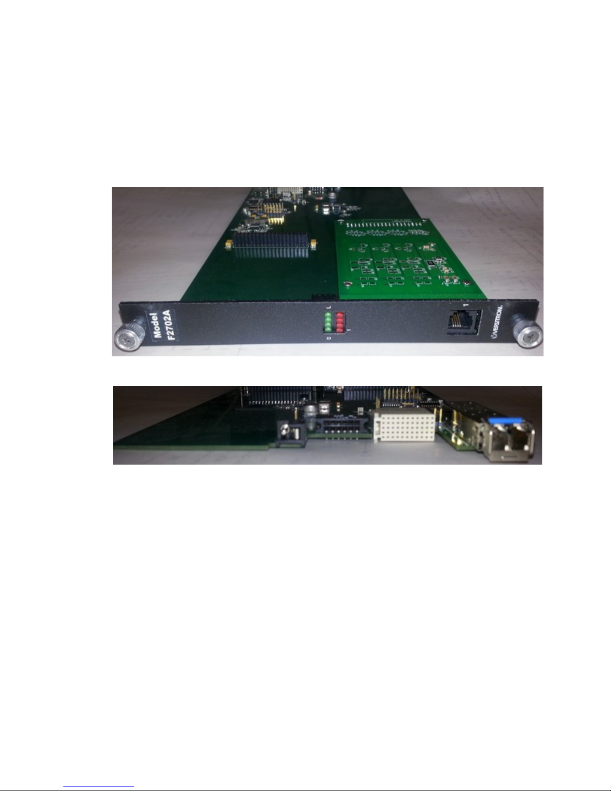
troubleshooting information. Illustrations 1 and 2 provide an overall view of the telephone
modems.
1 DESCRIPTION OF EQUIPMENT
Illustration 1: Front View, F270XAD
Illustration 2: Rear View, F270XAD
1.2 DESCRIPTION OF EQUIPMENT
1.2.1 Functional Characteristics
The Model F270XAD Telephone Modem is a modem for exchange (PBX or direct dial
service from a telephone company) connected telephone lines. These units are designed to be used
with Model F271XAD, which supply a subscriber (telephone handset) interface. When
configured in this way, the modems provide a fiber optic link for regular, 2-wire analog
telephones. The main characteristics of the Model F270XAD are:
Transparent extension of telephone lines.
SFP Based optics.
Supports RS-485/RS-422 full duplex data up to 64kbps.
Supports data up to 14.4kbps via dial-up modem or facsimile.
Model F270XAD and F271XAD modem pairs use SFP optic modules to achieve transmit
distances of up to 20km over a single pair of fiber-optic cable. Alternatively, these telephone
3 www.versitron.com
Page 4

modems can be used in a VMX20 Versimux II chassis, which can multiplex up to 19 telephone
modems on a single pair of fiber-optic cables.
1.2.2 Audio Transmission Characteristics
The F270XAD accepts a telephone audio signal on its RJ11 connector from the exchange,
and digitizes it with an analog-to-digital converter. Each of the digital samples is then encoded
and applied to the SFP for transmission over the fiber-optic cable.
The remote F271XAD unit decodes the signal from the SFP module and applies it to a
digital-to-analog converter to recover the analog audio. The converse occurs in the other
direction for the F270XAD.
The telephone modem transmits analog signals of 300 to 3400Hz.
1.2.3 RS-485 Transmission Characteristics
The F270XAD accepts balanced RS-485/RS-422 data on the RJ45 connector for
transmission across the fiber-optic line. Data speeds of up to 64kbps are achievable. This
interface is full duplex only.
1.2.4 Physical Characteristics
The telephone modems measure 7.0" wide x 0.84" high x 11.6" deep (17.8 x 2.1 x 28.9
cm) and are designed to be mounted in a variety of VERSITRON enclosures and chassis (see
Table 1 for dimensions of enclosures and chassis). "Desktop" option is a single-card enclosure.
Rack-mount options include a 2-Slot and 20-Slot 19” standard rack-mountable chassis. For
either desktop enclosure or 2-Slot rack-mount chassis, each F270XAD unit requires a wall
transformer, VERSITRON Model PSAC08 (US) or PSAC09 (European), providing 12 VDC,
1.0A. The one-pin power connector for electrical input is on the back of the card. There is a
RJ11 jack for the telephone line on the front of the card. There is an SFP module slot on the back
of the card for the SFP fiber-optic interface. For HF-20A chassis installations, power is provided
by VERSITRON Model AC300WR Power Supply / System Monitor, through the twelve pin
connector (P1). For Versimux II installations, power is provided to the VMX20 chassis by
VERSITRON Model AC300WR Power Supply / System Monitor, through the twelve pin
connector, and the link connection is provided by the backplane connector (J5). In Versimux II
installations the SFP module will be deactivated, and link communications will occur over the
backplane connector J5. Therefore, the SFP need not be populated in Versimux II installations.
Both F270XAD and F271XAD models have eight indicator LEDs as described in Table 2.
Table 1: Dimensions of Enclosures and Chassis
Model #
(Part #)
HF-1
(19052)
HF-2SS
(19629)
HF-20A
(32406)
VMX20
(32458)
*¹ Note: US Model – PSAC08; European Model – PSAC09
*² Note: One Power Supply per Modem required.
Dimensions Description Power Supply Required*¹
1.3" H x 7.1" W x 11.6" D
(3.3 x 18.0 x 29.5 cm)
1.7" H x 19.0" W x 13.8" D
(4.3 x 48.0 x 35.0 cm)
7.0" H x 19.0" W x 11.6" D
(17.8 x 48.0 x 29.5 cm)
7.0" H x 19.0" W x 11.6" D
(17.8 x 48.0 x 29.5 cm)
Single Card Desktop Enclosure
Dual Card Rack-Mount Chassis*²
(Side-by-Side)
20 Card Rack-Mount Chassis
20 Card Rack-Mount Chassis
(19 Multiplexed Slots)
4 www.versitron.com
PSAC08 PSAC09
(LTWPD1210PLX) (LTWPD1210EPL)
PSAC08 PSAC09
(LTWPD1210PLX) (LTWPD1210EPL)
AC300WR
(32410)
AC300WR
(32410)
Page 5
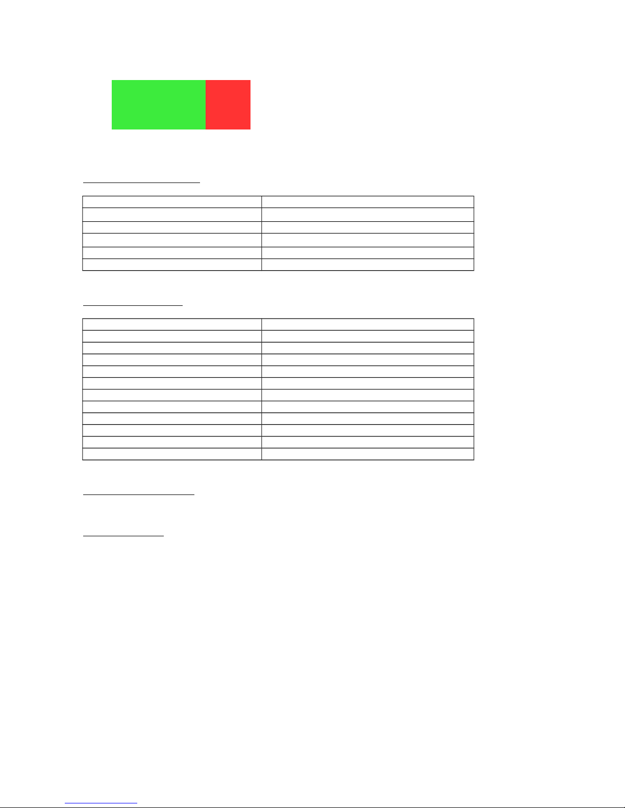
Table 2: Front Panel Status LEDs
Link Not Used
TX Not Used
RX Not Used
System Port 1
1.3 Telephone Modem Specification:
1.3.1 General Specifications:
Models F270XAD /F271XAD
Dimensions
Weight 0.28 kg (10.0 oz)
Operating Temperature
Humidity Up to 95% relative humidity (non-condensing)
Altitude Up to 10,000 ft
1.3.2 Electrical Interface:
Models F270XAD /F271XAD
Power Requirements 12VDC, 1.0Amp
Phone Connectors (Tip & Ring) RJ11, 2-Wire Twisted Pair
Audio Signal Analog, 300Hz to 3.4Khz
Idle Channel Noise - 65dBm
Single Frequency Distortion -46dB
2nd Harmonic Distortion -55dB
Talk Battery 44 to 52 VDC
Loop Current 40mA max (off hook)
Ring Signal 92Vpeak(max), 15 to 67Hz
Line Impedance 600Ω
RS-485 Data Rate 64kbps Max
(7 H x 7/8 W x 11 L) (17.8 x 2.1 x 27.9 cm)
0 to 50C (32 to 100F)
1.3.3 Fiber-Optic Interface:
See SFP module datasheet.
1.3.4 Major Features:
Intercom or Ring Down Application with two Subscribers, F271XAD
Will accept a range of SFP modules for Fiber-optic interface
VERSITRON Versimux II compatibility.
Supports RS-485/RS-422 full duplex data up to 64kbps.
Supports data up to 14.4 kbps via dial-up modem of facsimile
NOTE: F270XAD and F271XAD are not backward compatible with F270X and F271X
5 www.versitron.com
Page 6

2 INSTALLATION
2.1 GENERAL
This section contains detailed information on the installation and initial checkout of the
F270XAD telephone modem. Section 2.2 contains general information on site selection and
mounting. Section 2.3 contains the description for selecting different options on the Modem.
Sections 2.4 and 2.5 contain detailed instructions for connecting Model F270XAD products to
your system. Section 2.6 contains initial checkout procedures.
2.2 SITE SELECTION AND MOUNTING
The Model F270XAD products are designed to be used as an interface extender for
exchange lines of a PBX or direct dial service from a telephone company. When connecting the
F270XAD to a PBX or direct dial service, the copper and fiber-optic cable should be securely
installed so as to prevent accidental disconnection. Care should be taken to ensure that the
copper and fiber-optic cables are not mechanically separated from the Modem during operation.
When installed in either desktop chassis or in the dual-card rack-mount chassis, space for the
power transformer must also be provided.
2.3 SWITCH AND JUMPER SETTINGS
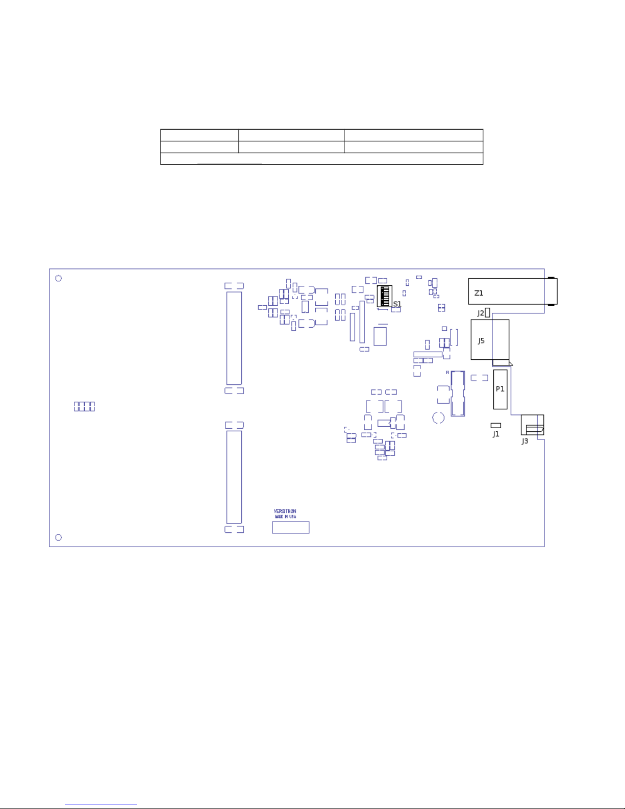
There is one set of switches and two jumpers provided for configuration of selectable
options. Switch and jumper locations are shown in Illustration 3. Switch and jumper settings are
as follows:
2.3.1 Multiplexer Configuration Settings
The F270XAD has one user selectable configuration setting to invert the RS485 data for
compatibility with MIL-STD-188-114.
Table 3: SW1 Switch Settings
Position On Off
SW1-1 Factory setting*
SW1-2 Factory setting*
SW1-3 Factory setting*
SW1-4 RS-485 Inverted Data RS-485 Normal Data
SW1-5 Factory setting*
SW1-6 Factory setting*
SW1-7 Factory setting*
SW1-8 Factory setting*
* Note: Factory settings as indicated. Do Not Change.
6 www.versitron.com
Page 7
2.3.2 SFP Module Settings
There are no user configurable SFP settings
Table 4: SFP Rate Jumper Settings(J2)
Jumper Jumped Functional Description
J2 Off* Do Not Change
*Note: Factory Setting: Do Not Change
2.3.3 Default Jumper
The remaining jumper (J1) is open and should not be changed.
Illustration 3: Switch and Jumper Locations
2.4 POWER REQUIREMENTS
The F270XAD products are designed to operate from an AC power transformer or a DC
power source in the range of +10 to +16 VDC.
2.4.1 Installation with AC Power
Before inserting the VERSITRON power transformer, PSAC08 (US) or PSAC09 (EUR),
into an AC power source, the plug should be connected to the Telephone Modem. There are no
special tools required.
7 www.versitron.com
Page 8
2.4.2 Installation with DC Power
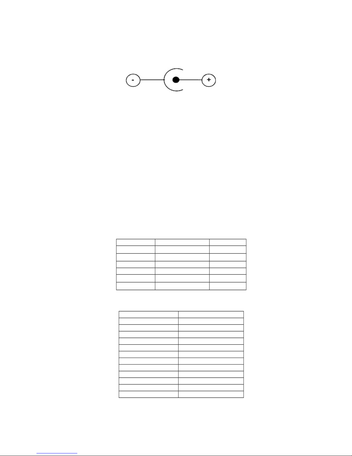
DC power may be used instead of a power transformer. This requires a 2.5 mm socket, J3
(location shown in Illustration 4) with the positive voltage on the center and the common on the
concentric supplying 12VDC at 1.0A as shown below (Illustration 4):
Illustration 4: DC Power Supply Connection
2.5 INTERFACE WIRING
Tables 5 and 6 list the interface wiring for F270XAD telephone modems. The
RJ11s are used with a single line 2-wire telephone as shown in Table 5. The modular connector
(J3) is wired in parallel with the 12-pin connector (P1) for power. When installing the telephone
modem in a standalone or dual-card rack-mount chassis, a power transformer is plugged into
barrel jack (J3). When installing the telephone modem in a 20-card rack-mount chassis (HF-20A
or VMX20) with optional power supplies (AC300WR) the 12-pin connector (P1) is used. Wiring
for the 12-pin connector is shown in Table 6. Hard Metric Type-C connector (J5) is used for
backplane communications, when the telephone modem is placed in a VMX20 chassis.
Illustration 3 identifies the locations for the 12-pin power connector (P1), barrel power jack (J3),
and HM Type-C (J5) connector. An RJ-45 jack is supplied to support RS-485/RS-422
connections as shown in Table 7.
Table 5: Telephone/Analog Wiring(all ports)
Pin Number Signal Designation Color
1 Not Used
2 Not Used
3 Ring Green
4 Tip Red
5 Not Used
6 Not Used
Table 6: (P1) Chassis Power/Alarm Wiring
Pin Number Signal Designation
1 +12 VDC
2 +12VDC
3 Signal Ground
4 Signal Ground
5 Signal Ground
6 Frame Ground (Chassis)
7 System Alarm Interface
8 Signal Ground
9 Signal Ground
10 +12 VDC
11 +12 VDC
12 +12 VDC
8 www.versitron.com
Page 9

Table 7: RS-485 Wiring
Pin Number Not Usedgnal Designation
1 RX+
2 RX3 TX4 Not Used
5 Not Used
6 TX+
7 Not Used
8 Not Used
2.5.1 Fiber-Optic Cable Installation
After the electrical and digital interface cables have been wired according to sections 2.4
and 2.5, insert the SFP module into the SFP cage (Z1) and attach the fiber-optic cable to it (see
Illustration 3 for location of Z1). The SFP module slides into the RFI Cage label side up. There
will be a slight click when it locks into place. After the SFP module is installed the fiber-optic
cable can be installed. The cable must be an LC type connection. The cable should be oriented
with the thumb tab at the top. When completely inserted the tabs will click into place.
2.6 INITIAL CHECKOUT PROCEDURE
F270XAD telephone modem contains no power on/off switch. Once power is connected
the modem will go through its power-up sequence. When the System LED (see Table 2) is lit the
modem is ready for use. Before beginning system operation check the following to verify proper
installation:
1. Verify that the power plug is seated fully into the modem or the modem is seated fully in the
rack-mount enclosure (HF20A or VMX20).
2. Verify that the fiber cable is connected on each end.
3. Verify that the Link LED (see Table 2) is lit when the fiber-optic cable is connected and the
units, both local and remote modems are powered.
If a malfunction is detected during the initial checkout procedure, refer to Section 5 for
information on isolating the malfunction in the unit.
9 www.versitron.com
Page 10
3.1 INTRODUCTION
This chapter contains a description of the operating controls and indicators associated with
the telephone modems. Since the F270XAD is designed for continuous and uninterrupted
operation, there are no setting requirements after the unit is operational. Once the unit is
powered up it should remain in service as long as required.
3.2 STATUS INDICATORS
There are five indicators used on the F270XAD: Link Status(Link), Transmit Data(TX),
Receive Data(RX), System Status(System), and one multi-function LED for the telephone port
(see Table 8 for descriptions).
Table 8: Status Indicators
LEDs* Color Function
Link Green Indicated the remote link is active and synchronized
TX Green Indicates transmit data (analog phone)
RX Green Indicates receive data (analog phone)
System Green Indicates System is active and configured (ready for operation)
Indicates the following :
1 Red
* See Table 2 for LED mapping
3 OPERATION
Off: Phone is On-Hook
On: Phone is either Off-Hook or Call is in progress
Flashing: Phone is ringing.
10 www.versitron.com
Page 11

4 THEORY OF OPERATION
4.1 INTRODUCTION
The F270XAD is an exchange side telephone modem with an SFP port for fiber-optic
connections. These Modems are designed to work with F271XAD subscriber side telephone
modems in pairs and interface with audio grade signals. These units are housed in VERSITRON
FOM II chassis: HF-1, HF-2SS and HF-20A or in a VMX20 Versimux II chassis. Chassis
descriptions are found in section 1.2.4.
4.2 POWER SUPPLY AND ALARM CIRCUITRY
4.2.1 Power Supply Circuit
When 12VDC is applied to the circuit, the unit should draw between 200mA and 1000mA
depending on the modem state. The unit has a series of switching power supply circuits, which
converts 12V to 3.3VDC, 1.8VDC, and 1.2VDC.
4.2.2 Alarm Circuit
This unit does not have an alarm circuit. Therefore, the Alarm signal on the P1 connector
will not be driven by this unit.
4.3 FUNCTIONAL DESCRIPTION
The unit consists of the following circuits:
4.3.1– Ring Detection
4.3.2– Analog-to-Digital Conversion
4.3.3– FPGA
4.3.4– Fiber-Optic Transceiver Circuit
4.3.5– Backplane Transceiver Circuit
4.3.1 Ring Detection
Ring detection is handled by the phone CODEC chipset. The chipset will detect ringing in
the range of 10Vrms to 35Vrms at a frequency range of 13Hz to 68Hz ..
4.3.2 Analog-to-Digital Conversion
Analog to Digital conversion is handled by the phone CODEC Chipset. A 16-bit sample is
gathered at an 8kHz sampling rate. On the return side Digital to Analog conversion is handled in
a similar way.
4.3.3 FPGA
The FPGA is used to transmit the digitized audio signal from the telephone port. In essence,
it is an asynchronous-to-synchronous converter encoded using proprietary VHDL programming
designed at VERSITRON. A 8.192MHz Oscillator, Y1, provides the clock input to the FPGA.
The FPGA also performs configuration operations for the phone CODEC chipset.
11 www.versitron.com
Page 12

4.3.4 Fiber-Optic Transceiver Circuit
Fiber-optic communications are handled by the SFP module. The power for this module is
isolated from the other power circuits through filters. This helps reduce the supply noise being
coupled into the SFP module. The SFP interfaces directly with the FPGA.
4.3.5 Backplane Transceiver Circuit
Backplane communications are handled by the FPGA. Upon insertion of the unit into a
Versimux II chassis the SFP module will be disabled, and serial communications will occur across
the backplane connection (J5).
12 www.versitron.com
Page 13

5 MAINTENANCE AND TROUBLESHOOTING
5.1 INTRODUCTION
This chapter contains general information designed to isolate a malfunction in the Model
F270XAD to a replaceable unit. These units are not equipped with redundancy. Therefore, a
failure in one of these units would interrupt service.
5.2 FAULT ISOLATION
The steps in Table 9 should be taken to check a non-operating modem. Contact
VERSITRON Customer Service for additional diagnostic assistance or to arrange for repair as
necessary.
Table 9: Non-Operational Indicators
STATUS INDICATOR PROBABLE CAUSE CORRECTIVE ACTION
System Status (System) LED is
OFF
Link Status (Link) LED is OFF Incorrect optical signal level received at
Port Indicator LED is ON Possible problems ranging from a
Modem is not working properly Default jumpers and switch settings are
No AC power Check that both ends of the transformer are
connected
Over current condition Power off the unit for a few minutes and retry
Other Contact VERSITRON for assistance
1. Check that fiber-optic cables are properly
receiver input
telephone set in an Off-Hook position to
a problem with the Off-Hook circuit
not set properly
connected
2. Check that the remote unit power is on and the
fiber-optic connectors are properly attached
3. Check that the SFP module on each end is
seated properly
4. Contact VERSITRON for assistance
Check if the telephone set receiver is seated in the
cradle correctly. If this is not the case, contact
VERSITRON for assistance
Check if SW1 positions are all off
Check that jumper J2 is off
Contact VERSITRON for assistance
13 www.versitron.com
 Loading...