

Versitron F270XA, F271XA Technical Manual

F271XA
Fiber-Optic
Telephone Modem
Technical Manual
Revision B
© August 2011
VERSITRON, Inc.
83 Albe Drive / Suite C
Newark, DE 19702
www.versitron.com
Safeguarding Communications Since 1958

CAUTION!!!! WARNING!!!!
DO NOT CONNECT THE F271XA SUBSCRIBER UNIT TO THE PBX SIDE OF
THE CIRCUIT AS THIS MAY RESULT IN DAMAGE TO THE F271XA.
SUCH DAMAGE IS NOT COVERED BY THE WARRANTY.
PROPRIETARY DATA
All data in this manual is proprietary and may not be disclosed,
used or duplicated, for procurement or manufacturing purposes,
without prior written permission by VERSITRON.
VERSITRON LIFETIME WARRANTY
All VERSITRON products are covered by a Lifetime Warranty against defects in materials and workmanship. This coverage
is applicable to the original purchaser and is not transferable.
We repair, or at our option, replace parts/products that, during normal usage and operation, are proven to be defective during
the time you own the products, provided that said products and parts are still manufactured and/or available. Such
repair/replacement is subsequent to receipt of your product at our facility and our diagnostic evaluation and review of the unit.
Advance replacements are not provided as part of the warranty coverage.
This warranty does not cover damage to products caused by misuse, mishandling, power surges, accident, improper installation,
neglect, alteration, improper maintenance, or other causes which are not normal and customary applications of the products
and for which they were not intended. No other warranty is expressed or implied, and VERSITRON is not liable for direct,
indirect, incidental or consequential damages or losses.
In the unlikely event a warranty issue should arise, simply contact us at 302-894-0699 or 1-800-537-2296 or via e-mail to
fiberlink@versitron.com and obtain a Return Material Authorization (RMA) number. Reference this number on the outside of
the shipping container and return the unit (shipping charges prepaid) to us for diagnostic review and repair/replacement as
determined solely by VERSITRON. We pay the shipping charges to return the repaired unit or a replacement unit to you.
2 www.versitron.com
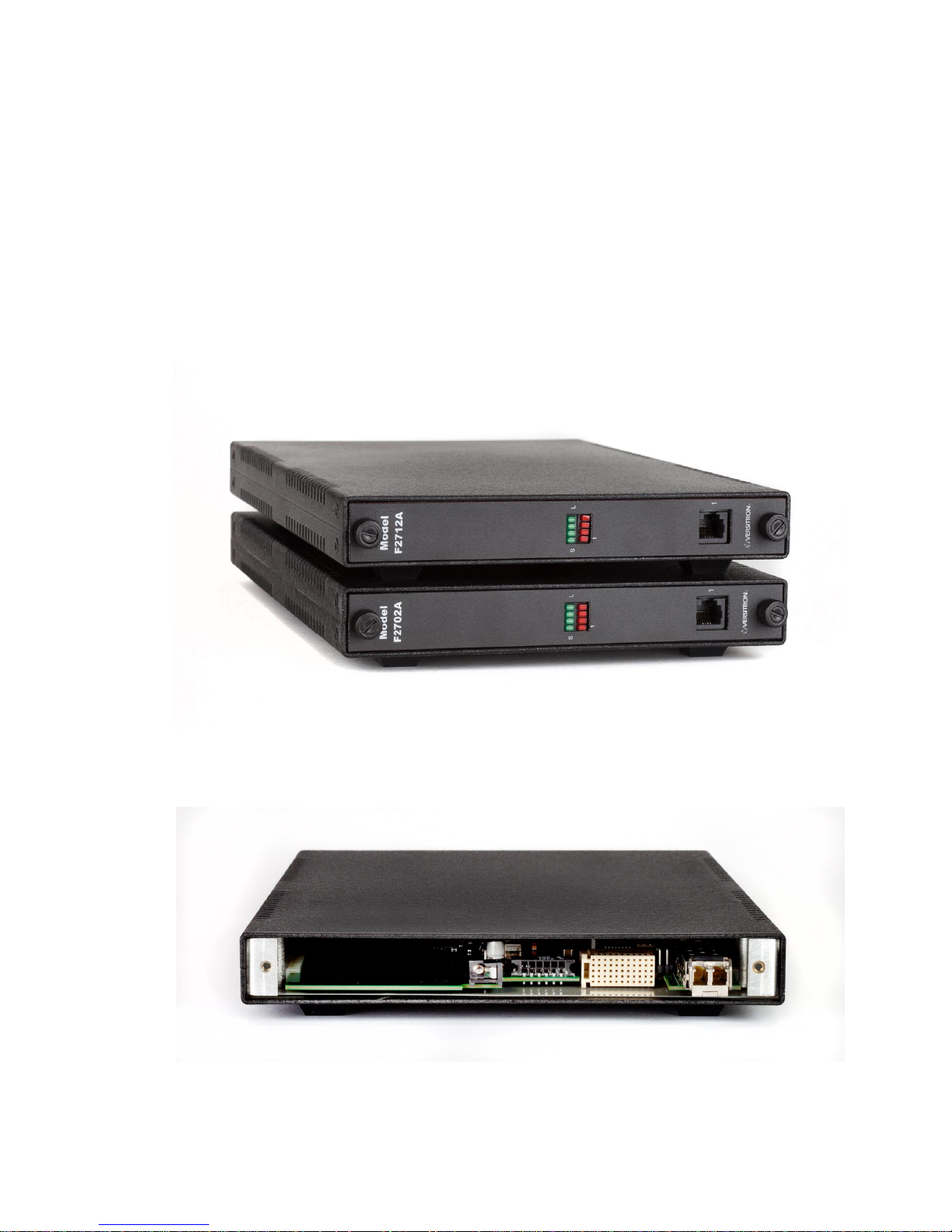
Figure 1: Front View, F271XA (Top Unit)
Figure 2: Rear View, F271XA
1.1 INTRODUCTION
This manual provides general and detailed information on the installation and operation of
the Model F271XA Fiber-Optic Telephone Modem. Section 1 provides a general description of
the equipment. Section 2 provides installation instructions. Section 3 provides operating
instructions. Section 4 provides the theory of operation. Section 5 provides maintenance and
troubleshooting information. Figure 1 and Figure 2 provide an overall view of the Telephone
Modems.
1 DESCRIPTION OF EQUIPMENT
3 www.versitron.com

1.2 DESCRIPTION OF EQUIPMENT
1.2.1 Functional Characteristics
The Model F271XA Telephone Modem is an extender for subscriber (telephone handset)
connected telephone lines. These units are designed to be used with Model F270XA, which supply
an exchange (PBX or direct dial service from a telephone company) interface. When configured
in this way, the modems provide a fiber optic link for regular, 2-wire analog telephones. The main
characteristics of the Model F271XA are:
Transparent extension of telephone lines.
SFP Based optics.
Supports data up to 14.4kbps via dial-up modem or facsimile.
Model F270XA and F271XA modem pairs use SFP optic modules to achieve transmit
distances of up to 20km over a single pair of fiber-optic cable. Alternatively, these telephone
modems can be used in a VMX20 Versimux II chassis, which can multiplex up to 19 telephone
modems on a single pair of fiber-optic cables.
1.2.2 Audio Transmission Characteristics
The F271XA accepts a telephone audio signal on the RJ11 connector from the subscriber,
digitizes it with an analog-to-digital converter. The digital samples are then encoded and applied
to the SFP for transmission over the fiber-optic cable.
The remote F270XA unit decodes the signal from the SFP module, and applies the samples
to a digital-to-analog converter to recover the analog audio. The converse occurs in the other
direction for the F271XA.
The telephone modem transmits analog signals of 300 to 3400Hz.
1.2.3 Physical Characteristics
The telephone modems measure 7.0" wide x 0.84" high x 11.6" deep (17.8 x 2.1 x 28.9 cm)
and are designed to be mounted in a variety of VERSITRON enclosures and chassis (see Table 1
for dimensions of enclosures and chassis). "Desktop" option is a single-card enclosure. Rackmount options include a 2-Slot and 20-Slot 19” standard rack-mountable chassis. For either
desktop enclosure or 2-Slot rack-mount chassis, each F271XA unit requires a wall transformer,
VERSITRON Model PSAC08 (US) or PSAC09 (European), providing 12 VDC, 1.0A. The onepin power connector for electrical input is on the back of the card. There is a RJ11 jack for the
telephone line on the front of the card. There is an SFP module slot on the back of the card for the
SFP fiber-optic interface. For HF-20A chassis installations, power is provided by VERSITRON
Model AC300WR Power Supply / System Monitor, through the twelve pin connector (P1). For
Versimux II installations power is provided to the VMX20 chassis by VERSITRON Model
AC300WR Power Supply / System Monitor, through the twelve pin connector, and the link
connection is provided by the backplane connector (J5). In Versimux II installations the SFP
module will be deactivated, and link communications will occur over the backplane connector J5.
Therefore, the SFP need not be populated in Versimux II installations. Both F270XA and F271XA
models have eight indicator LEDs as described in Table 2.
4 www.versitron.com

Model #
(Part #)
Dimensions
Description
Power Supply Required*¹
HF-1
(19052)
1.3" H x 7.1" W x 11.6" D
(3.3 x 18.0 x 29.5 cm)
Single-Card Desktop Enclosure
PSAC08 PSAC09
(LTWPD1210PLX) (LTWPD1210EPL)
HF-2SS
(19629)
1.7" H x 19.0" W x 13.8" D
(4.3 x 48.0 x 35.0 cm)
2-Slot Rack-Mount Chassis*²
(Side-by-Side)
PSAC08 PSAC09
(LTWPD1210PLX) (LTWPD1210EPL)
HF-20A
(32406)
7.0" H x 19.0" W x 11.6" D
(17.8 x 48.0 x 29.5 cm)
20-Slot Rack-Mount Chassis
AC300WR
(32410)
VMX20
(32458)
7.0" H x 19.0" W x 11.6" D
(17.8 x 48.0 x 29.5 cm)
20-Slot Rack-Mount Chassis
(19-Multiplexed Slots)
AC300WR
(32410)
Link
Not Used
TX
Not Used
RX
Not Used
System
Port 1
Table 1: Dimensions of Enclosures and Chassis
*¹ Note: US Model – PSAC08; European Model – PSAC09
*² Note: One Power Supply per Modem required.
Table 2: Front Panel Status LEDs
5 www.versitron.com
 Loading...