

Page 1

F270X
Fiber Optic
Tele-Data Modem
Technical Manual
Revision B
Copyright May 2002
VERSITRON, Inc.
83 Albe Drive / Suite C
Newark, DE 19702
www.versitron.com
A020519685
Page 2

PROPRIETARY DATA
All data in this manual is proprietary and may not be disclosed,
used or duplicated, for procurement or manufacturing purposes,
without prior written permission by VERSITRON, Inc.
WARRANTY
All VERSITRON products purchased after January 2001 are warranted against defects in materials and workmanship for
the lifetime of the product. Purchases made prior to January 2001 are warranted for a period of one year from date of
delivery. VERSITRON reserves the right to repair or, at our option, replace parts which during normal usage prove to be
defective during the warranty period provided that:
1. You call VERSITRON at (302) 894-0699 or (800) 537-2296 and obtain a Return Maintenance Authorization
(RMA) number. Please reference your RMA number on the outside of the shipment box.
2. Shipping charges are pre-paid.
No other warranty is expressed or implied and we are not liable for consequential damages. For repairs outside
of the warranty period, the same procedure must be followed.
ii www.versitron.com
Page 3

TABLE OF CONTENTS
PARAGRAPH TITLE PAGE
SECTION 1: DESCRIPTION OF EQUIPMENT
1.1 INTRODUCTION .......................................................................................................... 1
1.2 DESCRIPTION OF EQUIPMENT................................................................................. 1
1.2.1 Functional Characteristics ................................................................................................. 1
1.2.2 Audio and Data Transmission Characteristics .................................................................... 2
1.2.3 Physical Characteristics..................................................................................................... 2
1.3 TELE-DATA MODEM SPECIFICATIONS................................................................... 5
SECTION 2: INSTALLATION
2.1 GENERAL ...................................................................................................................... 6
2.2 SITE SELECTION AND MOUNTING.......................................................................... 6
2.3 SWITCH AND JUMPER SETTINGS............................................................................. 6
2.3.1 RS-485 / RS-422 Data Transmission Settings ................................................................... 6
2.3.2 Fiber Optic or Copper Transceiver Network Settings........................................................ 7
2.3.3 Interface Impedance Selection.......................................................................................... 7
2.3.4 Default Jumper ................................................................................................................. 8
2.4 POWER REQUIREMENTS............................................................................................ 8
2.4.1 Installation with AC Power ............................................................................................... 8
2.4.2 Installation with DC Power ............................................................................................... 8
2.5 INTERFACE WIRING................................................................................................... 9
2.5.1 Fiber Optic Cable Installation............................................................................................10
2.6 INITIAL CHECKOUT PROCEDURE............................................................................10
3.1 INTRODUCTION ..........................................................................................................11
3.2 STATUS INDICATORS / AUDIBLE ALARM...............................................................11
SECTION 3: OPERATION
iii www.versitron.com
Page 4

SECTION 4: THEORY OF OPERATION
PARAGRAPH TITLE PAGE
4.1 INTRODUCTION ..........................................................................................................12
4.2 POWER SUPPLY AND ALARM CIRCUITRY.............................................................12
4.2.1 Power Supply Circuit........................................................................................................12
4.2.2 Alarm Circuit....................................................................................................................12
4.3 FUNCTIONAL DESCRIPTION ....................................................................................13
4.3.1 Ring Detection..................................................................................................................13
4.3.2 Loop Current Detection Circuit.........................................................................................13
4.3.3 Reverse Battery Detection Circuit .....................................................................................13
4.3.4 Analog-to-Digital Conversion............................................................................................13
4.3.5 CPLD (Mux / Demux)......................................................................................................13
4.3.6 RS-485 / RS-422 Data Transmission Circuit.....................................................................14
4.3.7 Fiber Optic / Copper Transceiver Circuit ..........................................................................14
SECTION 5: MAINTENANCE AND TROUBLESHOOTING
5.1 INTRODUCTION ..........................................................................................................15
5.2 FAULT ISOLATION......................................................................................................15
iv www.versitron.com
Page 5

LIST OF ILLUSTRATIONS
FIGURE TITLE PAGE
1.1 FRONT VIEW, F270X MODEM ................................................................................... 3
1.2 REAR VIEW, F270X MODEM ...................................................................................... 3
1.3 BACK PANEL, F270X MODEM................................................................................... 3
1.4 APPLICATION EXAMPLE ........................................................................................... 4
1.5 SWITCH AND JUMPER SETTINGS............................................................................. 8
1.6 DC POWER SUPPLY CONNECTIONS....................................................................... 8
LIST OF TABLES
TABLE TITLE PAGE
1. DIMENSIONS OF ENCLOSURES AND CHASSIS .................................................... 2
2. SW1 SWITCH SETTINGS............................................................................................. 6
3. JP4 JUMPER SETTINGS ............................................................................................... 7
4. SW2 SWITCH SETTINGS............................................................................................. 7
5. LINE IMPEDANCE JUMPER SETTINGS ................................................................... 7
6. (J4) TELEPHONE / ANALOG WIRING........................................................................ 9
7. (P1) CHASSIS POWER / ALARM WIRING................................................................. 9
8. (J1) RS-485 / RS-422 DATA TRANSMISSION WIRING............................................10
9. COPPER INTERFACE WIRING...................................................................................10
10. STATUS INDICATORS.................................................................................................11
11. NONOPERATIONAL INDICATORS ...........................................................................15
v www.versitron.com
Page 6

1.1 INTRODUCTION
Number
Number
This manual provides general and detailed information on the installation and operation of the Model
F270X FOM II Series Fiber Optic TeleData Modems. Section 1 provides a general description of the
equipment. Section 2 provides installation instructions. Section 3 provides operating instructions. Section 4
provides the theory of operation. Section 5 provides maintenance and troubleshooting information. Figures 1.1
and 1.2 provide an overall view of the Model F270X Tele-Data Modems.
SECTION 1
DESCRIPTION OF EQUIPMENT
Model
F2702 19685-02
F2704 19685-04
F2705 19685-05
Part
Exchange side tele-data modem for audio and/or RS-485 or RS-422 data,
multimode, 850nm ST optics, 2 Km operational distance.
Exchange side tele-data modem for audio and/or RS-485 or RS-422 data,
multimode, 1300nm ST optics, 8 Km operational distance.
Exchange side tele-data modem for audio and/or RS-485 or RS-422 data,
single mode, 1300nm St optics, 14 Km operational distance.
1.2 DESCRIPTION OF EQUIPMENT
1.2.1 Functional Characteristics
The Model F270X Fiber Optic Modems are designed to be used as an interface extender from a singleline exchange of a PBX or direct dial service from a telephone company. These units are used with Model
F271X Fiber Optic Modems that provide a subscriber interface. These Modems are designed to transmit
audio (Telephone) and/or data (RS-485 or RS-422) on duplex fiber or 4-wire twisted pair cable (depending on
the application). The main characteristics of Model F270X Tele-Data Modems are:
Description
• Multiplexes Data (RS-485 or RS-422) and Analog (Telephone audio signal), if desired
• Transmits multiplexed Data / Audio signal on fiber optic or copper interface cables
Model F270X and F271X Modem pairs use multimode fiber optic cable of up to 2 Km (6,560 ft/1.2 mi)
for 850nm LED optics, up to 8 Km (26,240 ft/5 mi) for 1300nm LED optics, or single mode fiber optic cable
of up to 14 Km (46,200 ft/8.7 mi) for 1300nm ELED optics. If a copper interface is used then up to 1 Km
(3,300 ft/.625 mi) 4-wire twisted pair cable may be used to complete the circuit between the exchange
(F270X) and subscriber (F271X) side modems.
Page 1 www.versitron.com
Page 7

1.2.2 Audio and Data Transmission Characteristics
The F270X series operates by accepting the audio signal at the RJ11 connector from the exchange and
digitizing it, using an A/D converter. This signal is then multiplexed with data (RS-485 or RS-422) signals
coming from the RJ45. The combined signal is applied to a light pulse and transmitted over fiber optic or 4-wire
twisted pair cable to the remote F271X series unit.
The remote F271X series unit converts the light pulse (in cases of fiber optic connection) back into an
electrical signal, demultiplexes the combined data / audio signal and applies the digitized signal to an A/D
converter to recover the audio signal. The separated data and audio signals are then sent to their respective
destinations. The outgoing signal path (subscriber-to-exchange) is similar. The audio signal is digitized and
multiplexed together along with the data (RS-485 or RS-422) signals and transmitted to the F270X series unit.
Finally, the F270X Modem recovers the audio and data signals.
The Model F270X / F271X transmits analog signals of 300 to 3400Hz and full duplex asynchronous or
isochronous data (RS-485 or RS-422) signals up to 64Kbps and is fully transparent.
1.2.3 Physical Characteristics
Model F270X / F271X FOM II Series Tele-Data Modems measure 7.0 x 0.85 x 11.8in, HWD, (17.78
x 2.2 x 29.98cm) and are designed to be mounted in a variety of VERSITRON enclosures and chassis (see
Table 1 for dimensions of enclosures and chassis). "Desktop" options include both single- and dual-card
enclosures. Rack mount options include a 2-card and 20-card 19” standard rack mountable chassis. For
either desktop enclosure or 2-card rack mount chassis, each F270X / F271X unit requires a wall transformer,
VERSITRON Model PSAC08 (US) or PSAC09 (European), providing 12 VDC, 1A. The one-pin power
connector for electrical input is on the back of the card. There are two RJ11 jacks for the telephone and
copper interface (used in applications where there is no fiber optic cable), a RJ45 jack for EIA RS-485 or RS422 data connection and two ST connectors for the fiber optic interface, also on the back of the card as shown
in Figure 1.3. For HF-20 chassis installations, power is provided by VERSITRON Model AC150W Power
Supply / System Monitor. One AC150W utilizes two slots in the HF-20. Two AC150W units are
recommended for power redundancy. Both F270X and F271X models have six indicator LEDs: power
(PWR), off-hook (HOOK), ring signal (RING), loop detection (LOOP), reverse battery signal (RBAT), and
alarm (ALM). No audible alarm is available.
Model #
(Part #)
HF-1
(19052)
HF-2*²
(19053)
HF-2SS*²
(19629)
HF-20
(19032)
*¹ Note: US Model - PSAC08; European Model - PSAC09
*² Note: One Power Supply per Modem required.
Dimensions (WHD) Description Power Supply Required*¹
7.1 x 1.3 x 11.6in
(3.3 x 18.0 x 29.5cm)
7.1 x 2.3 x 11.6in
(5.9 x 18.0 x 29.5cm)
19.0 x 1.7 x 13.8in
(4.3 x 48.0 x 35.0cm)
19.0 x 7.0 x 11.6in
(17.8 x 48.0 x 29.5cm)
TABLE 1: DIMENSIONS OF ENCLOSURES AND CHASSIS
Single Card Standalone Enclosure
Dual Card Standalone Enclosure
2-Slot Rack Mount Chassis
20-Slot Rack Mount Chassis
PSAC08 PSAC09
(LTWPD1210PLX) (LTWPD1210EPL)
PSAC08 PSAC09
(LTWPD1210PLX) (LTWPD1210EPL)
PSAC08 PSAC09
(LTWPD1210PLX) (LTWPD1210EPL)
AC150W
(19320-03)
Page 2 www.versitron.com
Page 8
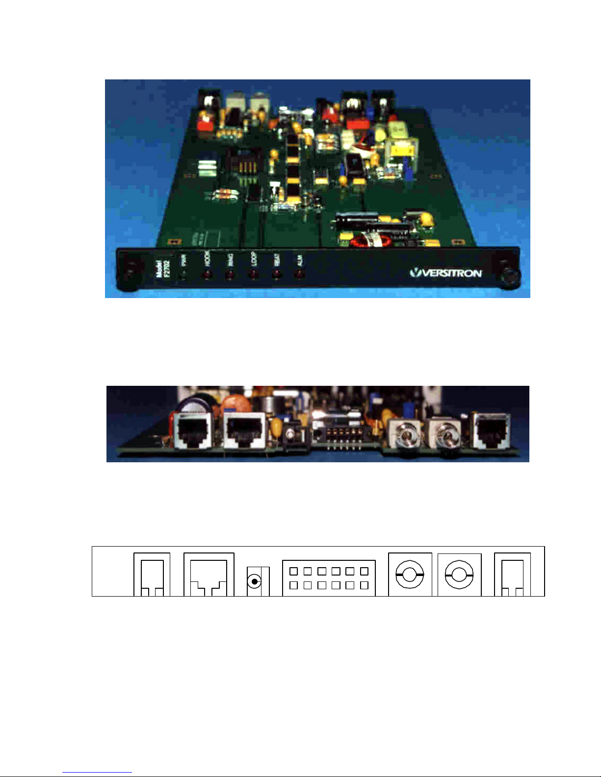
FIGURE 1.1 FRONT VIEW, F270X MODEM
FIGURE 1.2 REAR VIEW, F270X MODEM
RJ11 RJ45 TX RX RJ11 Power Jack
Audio Jack
(2-Wire)
Data Jack Optical Interface Copper Interface
FIGURE 1.3 BACK PANEL, F270X MODEM
12Pin Connector
Used For HF-20 Chassis 12VDC
(4-Wire)
Page 3 www.versitron.com
Page 9
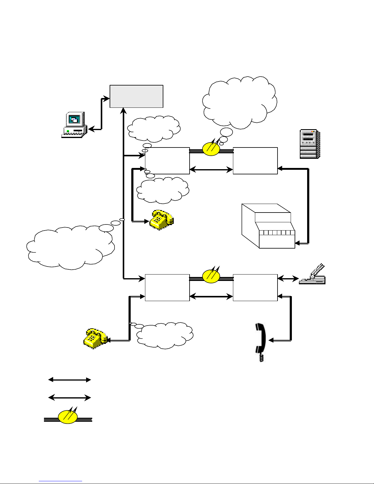
Full duplex,
Twisted Pair
Connector
Connector
Where,
4-Wire Twisted Pair
RS-485 / RS-422
RS232 to RS485
Converter
RJ45
RJ11
F271X
Subscriber
Modem
Fiber or copper
cable interfaces,
depending on
the application
Fiber Interface
Copper Interface
F270X
Exchange
Modem
DataCom
Product
i.e.; PLC
F271X
Subscriber
Modem
2-Wire
2-Wire Twisted Pair For Analog Signal
4-Wire Twisted Pair For Digital Signal
Duplex Fiber-optic Cable
FIGURE 1.4 APPLICATION EXAMPLE
Page 4 www.versitron.com
Fiber Interface
Copper Interface
F271X
Subscriber
Modem
Page 10

1.3 Specifications
General
Dimensions (WHD) 7.0 x .85 x 11.8in (17.78 x 2.2 x 29.98cm)
Weight 0.31kg (11.0oz)
Operating Temperature 0° to 50°C (32° to 100°F)
Humidity Up to 95% relative humidity (noncondensing)
Altitude Up to 10,000 ft
Electrical Interface
Power Requirements 12VDC, 1Amp
Connector (Tip & Ring) RJ11, 2-Wire Twisted Pair
Copper Interface Connector RJ11, 4-Wire Twisted Pair
Data Transmission Connector RJ45, CAT 5 UTP
Audio Signal Analog, 300Hz to 3.4Khz
Data Signal RS-485 or RS-422 asynchronous or isochronous
Data Rate Up to 64Kbps
Idle Channel Noise −55dBm
In-Band Spurious −40dBm
Out-Band Spurious −30dBm
Talk Battery 45 to 55 VDC
Loop Current 20mA max (off hook)
Ring Signal 80-150VAC, 15 to 68Hz
Line Impedance (Jumper selectable) 600 Ω or 900 Ω
Fiber Optic Interface
Models
Wavelength Multimode 850nm Multimode 1300nm Single Mode 1300nm
Connector ST ST ST
Link Budget 20 ± 1 dB 20 ± 1 dB 14 ± 1 dB
Maximum Range 2 Km 8 Km 14 Km
Fiber Optic Cable 50/125, 62.5/125, 100/140 50/125, 62.5/125,100/140 8/125, 9/125,10/125
F2702 / F2712 F2704 / F2714 F2705 / F2715
Features
• Intercom or Ring Down Application with two Subscribers, F271X
• Copper-to-Copper Option (Applications which don’t require fiber) maximum distance of 1000 feet
• Copper-to-Fiber Network Application Option
• 850nm Multimode, 1300nm Multimode, and 1300nm Single Mode Options
• Data and Audio Multiplexing
• Line Impedance Option of 600 Ω or 900 Ω
Page 5 www.versitron.com
Page 11

INSTALLATION
2.1 GENERAL
This section contains detailed information on the installation and initial checkout of the Model F271X
FOM II Series Modems. Paragraph 2.2 contains general information on site selection and mounting.
Paragraph 2.3 contains the description for selecting different options on the Modem. Paragraphs 2.4 and 2.5
contain detailed instructions for connecting Model F271X products to your system. Paragraph 2.6 contains
initial checkout procedures.
2.2 SITE SELECTION AND MOUNTING
The Model F270X FOM II modem is designed to be used as an interface extender from a single line
exchange of a PBX or direct dial service from a telephone company. This particular series can also be
connected directly to the serial port (RS-485 or RS-422) of terminal or data communication equipment with a
CAT-5 UTP cable (customer supplied). When connecting the F270X Modem to a PC, Fax, or STU III, the
copper and fiber optic cable should be securely installed so as to prevent accidental disconnection. Care should
be taken to ensure that the copper and fiber optic cables are not mechanically separated from the Modem
during operation. When installed in either desktop chassis or in the dual-card rack mount chassis, space for the
power transformer must also be provided.
SECTION 2
2.3 SWITCH AND JUMPER SETTINGS
Internal switches and jumpers are provided to select between available options on the F270X. Switch
and jumper locations are shown in figure 1.5. Switch and jumper settings are as follows:
2.3.1 RS-485 / RS-422 Data Transmission Settings
The F270X Modem has an option of changing the polarity of the transmit or receive data signals at the
RJ45 jack. This eliminates a need to reterminate the UTP cable and change the wiring in a RJ45 plug.
Position On Off
SW1-1 Factory setting* Factory setting*
SW1-2
SW1-3
SW1-4 Not used Not used
* Note: Factory setting for all SW1 positions is Off.
* Note: Do not set SW1-1 in the On position.
Inverts the phase/polarity for the
RS-485/RS-422 receiver inputs
Inverts the phase/polarity for the
RS-485/RS-422 transmitter outputs
TABLE 2: SW1 SWITCH SETTINGS
Normal phase/polarity for the
RS-485/RS-422 receiver inputs
Normal phase/polarity for the
RS-485/RS-422 transmitter outputs
Page 6 www.versitron.com
Page 12
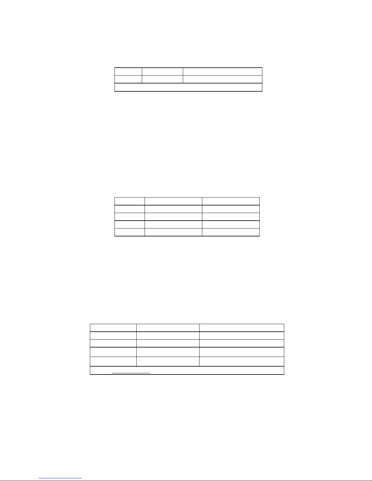
2.3.1 RS-485 / RS-422 Data Transmission Settings (cont’d)
Slew rate for the data being transmitted:
Jumped* Functional Description
JP4 2 & 3 Slew rate set to 10Mbps
* Note: Factory setting. Do not change.
TABLE 3: JP4 JUMPER SETTINGS
2.3.2 Fiber Optic or Copper Transceiver Network Settings
A new feature to the VERSITRON class of Modems is the ability of the F270X and F271X Series
Modems to multiplex data (RS-485 or RS-422) and analog (Telephone audio signal) onto a fiber OR copper
network, depending on the application. Figure 1.4 shows an example for a copper and fiber network circuit.
The selection for a copper (4-wire twisted pair) or a fiber optic interface is accomplished by the following dip
switch settings:
Position Copper Interface Fiber Interface
SW2-1 On Off
SW2-2 Off On
SW2-3 On Off
SW2-4 Off On
2.3.3 Interface Impedance Selection
The telephone / analog frequencies look into impedance known as the line impedance. In the USA and
North America it is about 600Ω. In Europe and the Far East it is usually 900Ω. F270X and F271X comply
with both standards, depending on the jumper settings. These settings are as follow:
Jumper Jumped* Functional Description
JP1 1 & 2 900 Ω line impedance
JP1 2 & 3 600 Ω line impedance
JP2
JP2
*Note: Factory Setting: JP1: (2 & 3 are jumped) and JP2: (Jumper on / in)
TABLE 5: LINE IMPEDANCE JUMPER SETTINGS
TABLE 4: SW2 SWITCH SETTINGS
Jumper off / removed
Jumper on / in
900 Ω line impedance
600 Ω line impedance
Page 7 www.versitron.com
Page 13
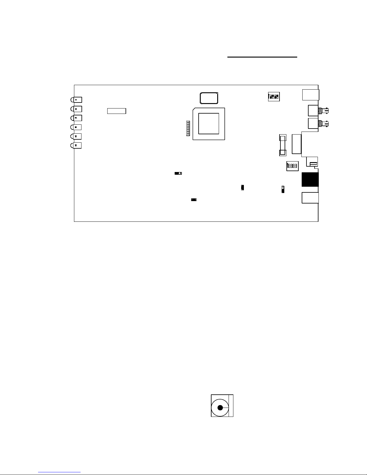
2.3.4 Default Jumper
The remaining jumper (JP3) is set in the default position and should not be removed. This jumper, if
removed, will cause the Modem not to work properly.
DS1
DS2
DS3
DS4
DS5
DS6
VERSITRON
MADE IN USA
FIGURE 1.5 SWITCH AND JUMPER SETTINGS
2.4 POWER REQUIREMENTS
JP1
JP5
Y1
U1
1
SW2
ON
4321
J7
RX
Z1
Z2
TX
P1
F1
SW1
ON
J3
4321
J1
JP4
JP3
JP2
J4
The Model F270X FOM II products are designed to operate from an AC power transformer or a DC
power source in the range of +12 to +18 VDC.
2.4.1 Installation with AC Power
Before inserting the VERSITRON power transformer, PSAC08 (US) or PSAC09 (EUR), into an AC
power source, the plug should be connected to the Modem. There are no special tools required.
2.4.2 Installation with DC Power
DC power may be used instead of a power transformer. This requires a 2.5 mm socket, J3 (location
shown in figure 1.5) with the positive voltage on the center and the common on the concentric supplying
12VDC at 1A as shown below:
FIGURE 1.6 DC POWER SUPPLY CONNECTIONS
Center = + 12VDC, 1A
Clip = Ground
Page 8 www.versitron.com
−−
++
Page 14

2.5 INTERFACE WIRING
Tables 7, 8, 9 and 10 list the interface wiring for Model F270X FOM II Series Modems. The RJ11 (J4)
is used with a single line 2-wire telephone. Wiring for (J4) is shown in Table 7. The modular connector (J3) is
wired in parallel with the 12-pin connector (P1) for power. When installing the telephone Modem in a
standalone or dual-card rack mount chassis, a power transformer is plugged into modular jack (J3). When
installing the telephone Modem in a 20-card rack mount chassis (HF-20) with optional power supplies
(AC150W) the 12-pin connector (P1) is used. Wiring for the 12-pin connector is shown in Table 7. RJ45 (J5)
is used for RS-485 or RS-422 data transmission. Wiring for J5 is shown in Table 9. RJ11 (J6) is used in
applications where data, audio or both are meant to transmit on a copper, instead of fiber optic network.
Settings for the copper interface are previously explained in section 2.3.3. Wiring for the copper interface is
shown in Table 10. Figure 1.5 identifies the locations for RJ11 jack (J4), 12-pin power connector (P1),
modular power jack (J3), RJ45 (J5) and RJ11 (J6) jacks.
Pin Number Signal Designation Color
1 Not Used
2 Not Used
3 Ring Green
4 Tip Red
5 Not Used
6 Not Used
TABLE 6: (J4) TELEPHONE / ANALOG WIRING
Pin Number Signal Designation
1 +12 VDC
2 +12 VDC
3 Signal Ground
4 Signal Ground
5 Signal Ground
6 Frame Ground (Chassis)
7 System Alarm Interface
8 Signal Ground
9 Signal Ground
10 +12 VDC
11 +12 VDC
12 +12 VDC
TABLE 7: (P1) CHASSIS POWER / ALARM WIRING
Page 9 www.versitron.com
Page 15

Interface SW1-2 SW1-3 Pin Number Signal Designation Color
1 RX+ Orange w/ White Line
Normal Phase/Polarity Off Off
Inverted Phase/Polarity On On
2 RX− Orange
3 TX− Green w/ White Line
6 TX+ Green
1 RX− Orange w/ White Line
2 RX+ Orange
3 TX+ Green w/ White Line
6 TX− Green
TABLE 8: (J5) RS-485 / RS-422 DATA TRANSMISSION WIRING
Pin Number Signal Designation Color
1 Not Used
2 RX− Yellow
3 RX+ Green
4 TX+ Red
5 TX− Black
6 Not Used
TABLE 9: (J6) COPPER INTERFACE WIRING
2.5.1 Fiber Optic Cable Installation
After the electrical and digital interface cables have been wired according to paragraphs 2.4 and 2.5,
attach the fiber optic cable to the F270X. The transmitter module of each unit should be connected to the
receiver module of the other unit. That is, the transmitter optic of the exchange side Modem, F270X, should be
connected to the receiver optic of the subscriber side Modem, F271X. On the other hand, the F271X
transmitter optic should be connected to the F270X receiver optic.
2.6 INITIAL CHECKOUT PROCEDURE
F270X Series Modems contain no power on/off switch. Once properly installed and power is applied it
should be fully operational. The power indicator should remain on as long as power is supplied to the unit.
Before beginning system operation check the following to verify proper installation:
1. Verify that the power plug is seated fully into the Modem or into the rack mount enclosure.
2. Verify that the fiber cable is crossed transmit to receive from unit one to two and two to one.
3. Verify that the alarm LED goes out when the signal is applied to the optical receiver of the F270X, or when
4-wire UTP is connected between the F270X and F271X in a copper network application.
4. Verify the switch settings for the circuit configuration. (i.e. copper or fiber optic network interface).
If a malfunction is detected during the initial checkout procedure, refer to Section 5 for information on
isolating the malfunction in the unit.
Page 10 www.versitron.com
Page 16

SECTION 3
OPERATION
3.1 INTRODUCTION
This chapter contains a description of the operating controls and indicators associated with the Model
F270X FOM II Series Modems. Since the Model F270X is designed for continuous and uninterrupted
operation, there are no setting requirements after the unit is operational. Once the Modem is powered up it
should remain in service as long as required.
3.2 STATUS INDICATORS / AUDIBLE ALARM
There are 6 indicators on the Model F271X: power (PWR), off-Hook (HOOK), ring detect (RING),
loop detect (LOOP), reverse battery (RBAT), alarm (ALM). No audible alarm is available.
LEDs Color Function
PWR Green Indicates operating voltage is present at the power interface connector
HOOK Red Indicates that the telephone set has gone OFF-HOOK, when lit
RING Red Indicates RING signal coming from the exchange (switch), when lit or blinking
LOOP Red
RBAT Red Indicates Reverse Battery condition when lit
ALM Red
Indicates the successful loop closure on the exchange side Modem upon receiving an OFF-HOOK
signal from the subscriber side Modem, when lit
Indicates the following when lit:
1. +5V power supply circuit is not working
2. –5V charge pump circuit is not working
3. +12V Power supply is not working
4. A problem exists with data transmission
TABLE 10: STATUS INDICATORS
Page 11 www.versitron.com
Page 17

SECTION 4
THEORY OF OPERATION
4.1 INTRODUCTION
The F270X is an exchange side Tele-Data Modem with ST single or multimode fiber optic connectors.
These Modems are designed to work with F271X subscriber side Modems in pairs and interface with audio
and RS-485 or RS-422 data grade signals. These units are housed in VERSITRON FOM II chassis: HF-1,
HF-2, HF-2SS and HF-20. Chassis descriptions are found in paragraph 1.2.3.
4.2 POWER SUPPLY AND ALARM CIRCUITRY
4.2.1 Power Supply Circuit
When 12VDC is applied to the circuit, the unit should draw between 100mA and 130mA depending on
the Modem state. The unit has a switching power supply circuit converting 12V to 5VDC and a charge pump
circuit converting 5V to −5VDC. The switching power supply has a switching frequency of 44.4Khz
determined by capacitor C28 (1800pF) and an under voltage lockout feature. This feature is produced by CR5
(1N755) and CR6 (1N4148). The under voltage lockout is accomplished as follows:
When the input voltage becomes lower than the zener breakdown voltage, the output transistor is turned
off. This occurs because diode CR6 at that time becomes forward bias, allowing resistor R42 to sink a greater
current from the non-inverting input than is sunk by the parallel combination of R43 and R44 at the inverting
terminal.
4.2.2 Alarm Circuit
Alarm LED goes off when one of the following occurs:
1. +5V power supply circuit is not working
2. –5V charge pump circuit is not working
3. +12V power supply is not working
4. A problem exists with data transmission and a mux clock is not present at U5 (HC123)
These conditions activate the base of Q3, which activates the base of Q2 and starts current flowing
through DS6, the alarm LED. When Q2 is activated this also changes the voltage level of connector P1 pin 7
that activates the system alarm circuit on the power supply.
Page 12 www.versitron.com
Page 18

4.3 FUNCTIONAL DESCRIPTION
The unit consists of the following circuits:
4.3.1 Ring detection
4.3.2 Loop circuit detection circuit
4.3.3 Reverse battery detection circuit
4.3.4 Analog-to-digital conversion
4.3.5 CPLD (Mux / Demux)
4.3.6 RS-485 / RS-422 data transmission circuit
4.3.7 Fiber Optic / Copper transceiver circuit
4.3.1 Ring Detection
The Ring signal from the Central Office (which is normally 65 Vrms to 104 Vrms, with 20Hz ± 3Hz) is
detected by the optocoupler U14 and sent to CPLD, U1 via the D flip-flop U7. When there is no Ring signal,
C20 is charged to +5 and the D flip-flop is cleared.
4.3.2 Loop Current Detection Circuit
The Loop indication signal can be detected only when there is an ON-HOOK condition at the subscriber
side Modem. The current supplied by the central office can vary from 17mA to 25mA. When this condition is
present U13 optocoupler detects the current and discharges C23 (68µF) to trigger the LOOP signal or LED.
4.3.3 Reverse Battery Detection Circuit
Normally Tip is 48VDC with respect to Ring. When this condition is reverse, that is Ring is 48VDC with
respect to Tip, U12 optocoupler detects the condition and triggers the REVBAT signal which turns on the
RBAT LED.
4.3.4 Analog-to-Digital Conversion
A 2W / 4W Hybrid circuit is used before the A/D circuit, this signal is then digitized and band limited for
the digital system. On the reverse path the digital data stream is reconstructed into an analog audio signal. The
sampling rate on the audio signal is 256Khz to ensure signal quality.
4.3.5 CPLD (Mux / Demux)
The CPLD is used to mux / demux the digitized audio and RS-485 or RS-422 digital data signal. In
essence, it is an asynchronous-to-synchronous converter encoded using proprietary VHDL programming
designed at VERSITRON. A 20MHz Oscillator, Y1, provides the clock input to the CPLD.
Page 13 www.versitron.com
Page 19

4.3.6 RS-485 / RS-422 Data Transmission Circuit
In the data transmission circuit, a RS-485 / RS-422 interface IC, U18, is used. This IC takes in a
balanced data signal and converts it into a TTL signal. The TTL data signal is then fed to the CPLD, where it is
multiplexed with the digitized audio signal. During the data reception, the TTL signal is obtained from the
CPLD, which then enters the interface IC. Here the data is reformatted to a RS-485 or RS-422 signal and is
transmitted out of the RJ45 connector.
4.3.7 Fiber Optic / Copper Transceiver Circuit
This design has an option of multiplexing data (RS-485 or RS-422) and analog (Telephone audio signal)
onto either a copper or fiber network. The selection for a copper (4-wire twisted pair) or fiber interface is
accomplished by dip switch settings as described in paragraph 2.3.2.
When the multiplexed audio and data signals are transmitted out of the CPLD, it goes into the JFET, Q1
(VN10KM). By turning on and off Q1 JFET VN10KM, the fiber optic transmitter Z2 is turned on and off
respectively. This is how the optical signal is transmitted out of the Modem. On the receive side, optical
receiver Z1 takes the optical signal from the fiber and converts it into a low voltage current. This current signal
is fed into the fiber optic quantizer IC, through a 0.01µF coupling capacitor, C8. This chip converts the low
voltage signal into a TTL signal, which then goes into the CPLD where the multiplexed audio and data signals
are de-multiplexed and sent to their respective destinations.
When a copper-to-copper interface is selected, the multiplexed audio and data signal is transmitted out of
the CPLD, which then goes into U17, a full duplex RS-485 / RS-422 interface IC. This chip converts the TTL
data signal into a RS-485 / RS-422 signal and is transmitted on a 4-wire twisted pair telephone wire. On the
reception side, U17, a full duplex RS-485 / RS-422 interface IC, receives the signal from a 4-wire UTP. The
RS-485 or RS-422 data signal is converted into a TTL data signal and is transmitted to the CPLD, U1. Here
the multiplexed audio and data signals are de-multiplexed and sent to their respective destinations.
Page 14 www.versitron.com
Page 20

SECTION 5
MAINTENANCE AND TROUBLESHOOTING
5.1 INTRODUCTION
This chapter contains general information designed to isolate a malfunction in the Model F270X to a
replaceable unit. These units are not equipped with redundancy. Therefore, a failure in one of these units would
interrupt service.
5.2 FAULT ISOLATION
The steps in Table 12 should be taken to check a nonoperating Modem. Contact VERSITRON
Customer Service for additional diagnostic assistance or to arrange for repair as necessary.
STATUS INDICATOR PROBABLE CAUSE CORRECTIVE ACTION
POWER (PWR) LED is OFF
ALARM (ALM) LED is ON Incorrect optical signal level received at
HOOK LED is ON Possible problems ranging from a
LOOP LED is ON Current supplied by the central office is
RBAT LED is ON Voltage between Tip and Ring are
Modem is not working properly Default jumpers and switch settings are
No AC power Check that both ends of the transformer are
connected
Blown Fuse Replace with 250V 1A slo-blo fuse
Other power supply circuit problem Contact VERSITRON for assistance
1. Check that fiber optic cables are properly
receiver input
telephone set in an Off-Hook position to
a problem with the Off-Hook circuit
fluctuating from 17mA to 25mA
reversed
not set properly
connected
2. Check that the remote unit power is on and the
fiber optic connectors are properly attached
3. Measure the optical levels on both ends (if
possible) in order to check the optical link
4. Contact VERSITRON for assistance
Check if the telephone set receiver is seated in the
cradle correctly. If this is not the case, contact
VERSITRON for assistance
Check the exchange the exchange line coming from
the central office or the Switch
Check that the Tip and Ring on the 2-wire UTP
coming from the central office are not reversed. That
is, Tip wire is not connected to the Ring on the
Modem’s RJ11 connector and vise versa
1. Check if SW1-1 is OFF and JP3 is not removed
2. Check if SW2 is properly set for the desired
interface (i.e. copper or fiber network
application, see table 4)
3. Contact VERSITRON for assistance
TABLE 11: NONOPERATIONAL INDICATORS
Page 15 www.versitron.com
 Loading...