

Versitron F242x Technical Manual

F242x
T1/E1 Fiber-Optic Modem
Technical Manual
Revision A
© July 2015
VERSITRON, Inc.
83 Albe Drive / Suite C
Newark, DE 19702
www.versitron.com
Safeguarding Communications Since 1958

PROPRIETARY DATA
All data in this manual is proprietary and may not be disclosed,
used or duplicated, for procurement or manufacturing purposes,
without prior written permission by VERSITRON.
VERSITRON LIFETIME WARRANTY
All VERSITRON products are covered by a Lifetime Warranty against defects in materials and workmanship. This coverage
is applicable to the original purchaser and is not transferable.
We repair, or at our option, replace parts/products that, during normal usage and operation, are proven to be defective durin g
the time you own the products, provided that said products and parts are still manufactured and/or available. Such
repair/replacement is subsequent to receipt of your product at our facility and our diagnostic evaluation and review of the unit.
Advance replacements are not provided as part of the warranty coverage.
This warranty does not cover damage to products caused by misuse, mishandling, power surges, accident, improper installation,
neglect, alteration, improper maintenance, or other causes which are not normal and customary applications of the products
and for which they were not intended. No other warranty is expressed or implied, and VERSITRON is not liable for direct,
indirect, incidental or consequential damages or losses.
In the unlikely event a warranty issue should arise, simply contact us at 302-894-0699 or 1-800-537-2296 or via e-mail to
fiberlink@versitron.com and obtain a Return Material Authorization (RMA) number. Reference this number on the outside of
the shipping container and return the unit (shipping charges prepaid) to us for diagnostic review and repair/replacement as
determined solely by VERSITRON. We pay the shipping charges to return the repaired unit or a replacement unit to you.

Table of Contents
1 Description of Equipment ................................................................................................................ 4
1.1 Introduction ............................................................................................................................................................... 4
1.2 Description of Equipment .......................................................................................................................................... 5
1.2.1 Functional Characteristics ................................................................................................................................. 5
1.2.2 Physical Characteristics .................................................................................................................................... 5
1.2.3 Specifications ............................................................................................................................................................. 7
2 Installation ......................................................................................................................................... 9
2.1 General ...................................................................................................................................................................... 9
2.2 Site Selection and Mounting ...................................................................................................................................... 9
2.3 Power Requirements ................................ ................................................................................................ .................. 9
2.4 Switch Settings .......................................................................................................................................................... 9
2.5 Output Connections ................................................................................................................................................. 11
2.6 Loopback ................................................................................................................................................................. 11
2.6.1 Fiber/Copper Loopback .................................................................................................................................. 11
2.6.2 Interface Loopback ......................................................................................................................................... 12
2.7 Initial Checkout Procedure ...................................................................................................................................... 12
3 Operation ......................................................................................................................................... 13
3.1 Introduction ............................................................................................................................................................. 13
3.2 Status Indicators and Alarm Circuits ....................................................................................................................... 13
3.3 Operating Controls................................................................................................................................................... 13
4 Theory of Operation ....................................................................................................................... 14
4.1 Introduction ............................................................................................................................................................. 14
5 Maintenance and Troubleshooting ................................................................................................ 15
5.1 Introduction ............................................................................................................................................................. 15
5.2 Fault Isolation .......................................................................................................................................................... 15
3 www.versitron.com
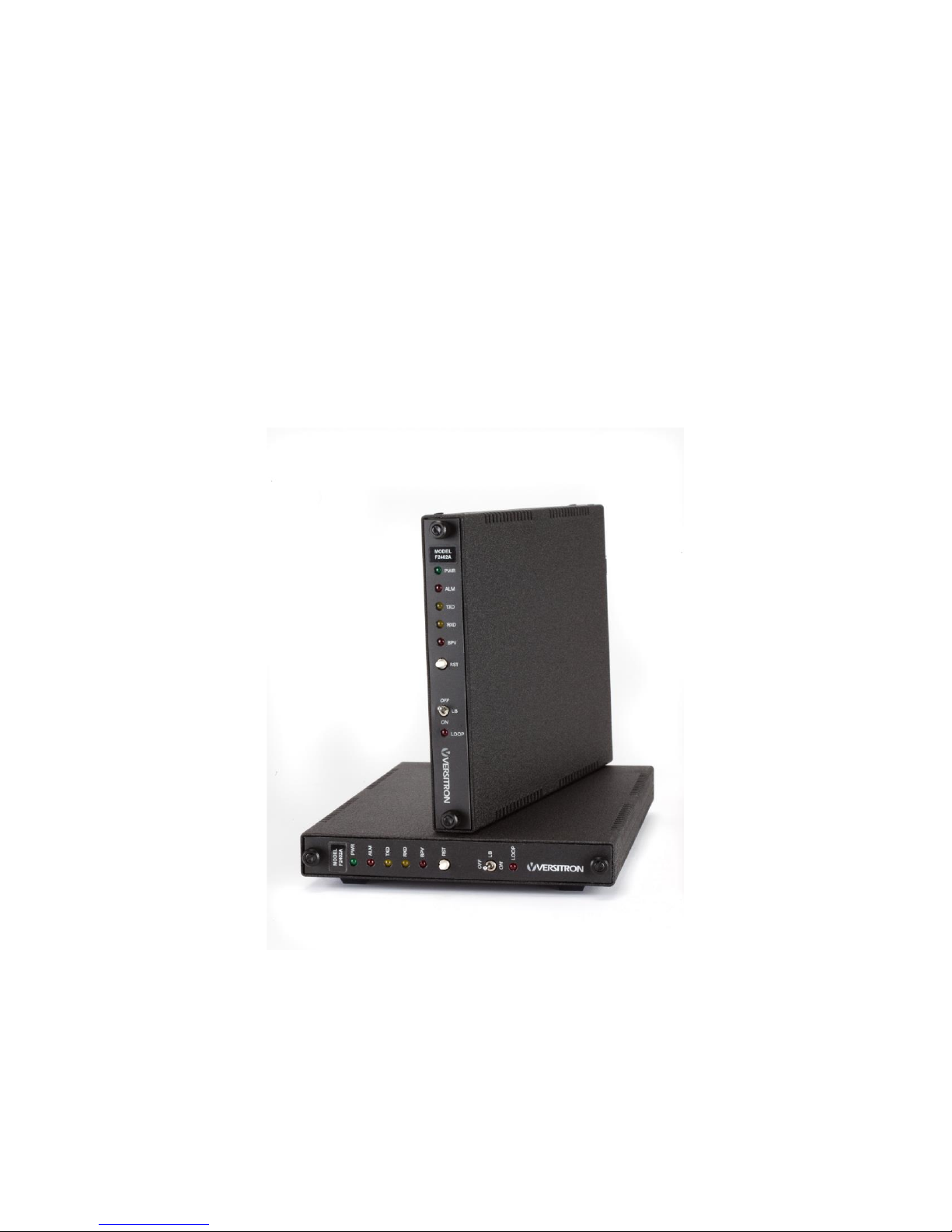
Figure 1: Overall View, F242x Fiber Optic Modem
1.1 Introduction
This manual provides general and detailed information on the installation and operation of
the Model F242x FOM II Series T1/E1 Fiber Optic Modems. Section 1 contains a general
description of the equipment. Section 2 contains installation instructions. Section 3 contains
operating instructions. Section 4 provides the theory of operation. Section 5 contains
maintenance and troubleshooting information. Figure 1 is an overall view of the F242x.
1 Description of Equipment
4 www.versitron.com

Model
Number
Description
F2422
T1/E1 fiber modem, multimode, 850nm LED, LC optics, 1.544Mbps/2.048Mbps,
distances to 2km.
F2425
T1/E1 fiber modem, single mode, 1310nm LED, LC optics,
1.544Mbps/2.048Mbps, distances to 20km.
Figure 2: Rear Connectors
1.2 Description of Equipment
1.2.1 Functional Characteristics
Model F242x modems are designed to operate as point-to-point converters for copper-tofiber T1/E1-standard interface extenders. F242x modems transmit over fiber optic cable up to
2km with multimode 850nm LEDs or up to 20km for single mode 1310nm LEDs. The fiber optic
circuit (two F242x modems connected by fiber cable) has data rates and electrical signal
characteristics that conform to ANSI T1.403, AT&T Pub. TR54016 and TR62411, and
G.703/G.704 standards. Electrical signals on copper cable are converted to fiber optic signals by
the F242x modem, and AMI or B8ZS/HDB3 data protocols are decoded.
1.2.2 Physical Characteristics
F242x modems measure 7.0W x 0.84H x 11.6L in. (17.8 x 21. X 28.9 cm) and are designed
for mounting in a variety of VERSITRON enclosures. Table 1 lists dimensions of enclosures and
chassis. Standalone option is a single card enclosure (HF-1). 19” rack mount options include 2slot chassis (HF-2SS), 20-slot chassis (HF-20A) and VERSITRON Versimux II chassis (VMX20).
Each F242x modem installed in an HF-1 or HF-2SS requires a power adapter Model PSAC08
(US) or PSAC09 (European) providing 12 VDC, 1A with a one-pin connector for electrical input
on the back of the card. Note: Other power adapters are available, such as UK and Australian.
5 www.versitron.com
 Loading...