

Page 1

F2238 / F2240 / F2245
FOM II Series
RS-530
High-Speed
Fiber Optic Modem
Technical Manual
June 2004
Copyright June 2004
VERSITRON, Inc.
83 Albe Drive / Suite C
Newark, DE 19702
www.versitron.com
E040619643
Page 2

PROPRIETARY DATA
All data in this manual is proprietary and may not be disclosed,
used or duplicated, for procurement or manufacturing purposes,
without prior written permission by
VERSITRON, Inc.
WARRANTY
All VERSITRON products are warranted against defects in materials and workmanship for a period of one year from
date of delivery. VERSITRON reserves the right to repair or, at our option, replace parts which during normal usage
prove to be defective during the warranty period provided that:
1. You call VERSITRON at 302-894-0699 or 800-537-2296 and obtain a Return Maintenance Authorization (RMA)
Number. Please reference your RMA number on the outside of the shipping box.
2. Shipping charges are pre-paid.
No other warranty is expressed or implied and we are not liable for consequential damages. For repairs outside of the
warranty period, the same procedure must be followed.
ii www.versitron.com
Page 3

TABLE OF CONTENTS
PARAGRAPH TITLE PAGE
SECTION 1: DESCRIPTION OF EQUIPMENT
1.1 INTRODUCTION .....................................................................................................1
1.2 DESCRIPTION OF EQUIPMENT ...........................................................................1
1.2.1 Functional Characteristics .........................................................................................1
1.2.2 Physical Characteristics.............................................................................................2
1.3 SPECIFICATIONS....................................................................................................4
SECTION 2: INSTALLATION
2.1 GENERAL.................................................................................................................5
2.2 SITE SELECTION AND MOUNTING....................................................................5
2.3 POWER REQUIREMENTS......................................................................................5
2.4 JUMPER SETTINGS ................................................................................................6
2.4.1 Polarity Straps............................................................................................................6
2.4.2 Jumpers For Input Impedance Selection....................................................................7
2.4.3 Jumpers For Transmit Clock Selection......................................................................7
2.4.4 Jumpers For Receive Clock Selection .......................................................................7
2.4.5 Settings for Balanced/Unbalanced Outputs...............................................................7
2.5 OUTPUT CONNECTIONIS .....................................................................................7
2.6 LOOPBACK..............................................................................................................8
2.7 INITIAL CHECKOUT PROCEDURE .....................................................................8
SECTION 3: OPERATION
3.1 INTRODUCTION .....................................................................................................9
3.2 STATUS INDICATORS ...........................................................................................9
3.3 BIT RATE MONITOR..............................................................................................9
3.4 CLOCK SELECT OPTIONS ....................................................................................9
SECTION 4: THEORY OF OPERATION
4.1 INTRODUCTION .....................................................................................................10
SECTION 5: MAINTENANCE AND TROUBLESHOOTING
5.1 INTRODUCTION .....................................................................................................11
5.2 FAULT ISOLATION ................................................................................................11
iii www.versitron.com
Page 4

LIST OF ILLUSTRATIONS
FIGURE TITLE PAGE
1. OVERALL VIEW .........................................................................................................2
2. MODEM LINK CONFIGURATION............................................................................3
3. MODEM JUMPER AND TEST POINT LOCATIONS ...............................................6
LIST OF TABLES
TABLE TITLE PAGE
1. ENCLOSURES / CHASSIS ..........................................................................................3
2. JUMPER SETTINGS ....................................................................................................6
3. ELECTRICAL (DB25) INTERFACE PINOUT ...........................................................8
4. NON-OPERATIONAL INDICATORS ........................................................................11
iv www.versitron.com
Page 5

SECTION 1
DESCRIPTION OF EQUIPMENT
1.1 INTRODUCTION
This manual provides general and detailed information on the installation and operation of
Model F22XX FOM II Series RS-530 High-Speed Fiber Optic Modems. Section 1 contains a
general description of the equipment. Section 2 contains installation instructions. Section 3
contains operating instructions. Section 4 provides the theory of operation. Section 5 contains
maintenance and troubleshooting information. Figure 1 is an overall view of the F22XX circuit
card assembly.
Model Number Part Number Description
RS-530 High-Speed Fiber Optic Modem, duplex,
F2238 19643-02
multimode, 850 nM, ST connectors, 250 Bps – 10 Mbps,
distances to 2 Km*.
RS-530 High-Speed Fiber Optic Modem, duplex,
F2240 19643-04
multimode, 1300 nM, ST connectors, 250 Bps – 10 Mbps,
distances to 6 Km*.
RS-530 High-Speed Fiber Optic Modem, duplex, single
F2245 19643-05
mode, 1300 nM, ST connectors, 250 Bps – 10 Mbps,
distances to 15 Km*.
* Note: Multimode tests performed @ 100 Kbps on 62.5/125 µM fiber optic cable.
Single mode tests performed @ 100 Kbps on 10/125 µM fiber optic cable.
1.2 DESCRIPTION OF EQUIPMENT
1.2.1 Functional Characteristics
Model F22XX modems are high-speed modems that allow the full duplex transmission of
data, clock and a control signal (data terminal ready (DTR), data set ready/data carrier detect
(DSR/DCD)) over fiber optic cable. Figure 2 shows the modem link configuration. The fiber
circuit consists of two modems connected by two fiber optic strands with data rates and electrical
signal characteristics that conform to EIA RS-530 and MIL-STD-188-114 balanced/unbalanced
standards. The modems provide synchronous or asynchronous data transmission at speeds up to
10 Mbps. The link is fully transparent in both directions and is data agile. Model F2238 modems
are installed with 850 nM multimode optics and operate at distances of up to 2 Km (1.25
mi./6,600 ft.) on multimode fiber cable. Model F2240 modems installed with 1300 nM
multimode optics operate at distances of up to 6 Km (3.7 mi./19,680 ft.) on multimode fiber
cable. Model F2245 modems installed with 1300 nM single mode optics operate at distances of
up to 15 Km (9.3 mi./49,100 ft.) on single mode fiber cable. Basically, model F22XX modems
operate as two channel multiplexers/modems. For high-speed synchronous operation the first
channel is used for data and the second for transmit clock. Both channels may be used for data
in low-speed, asynchronous operation at less than 100 Kbps.
1 www.versitron.com
Page 6
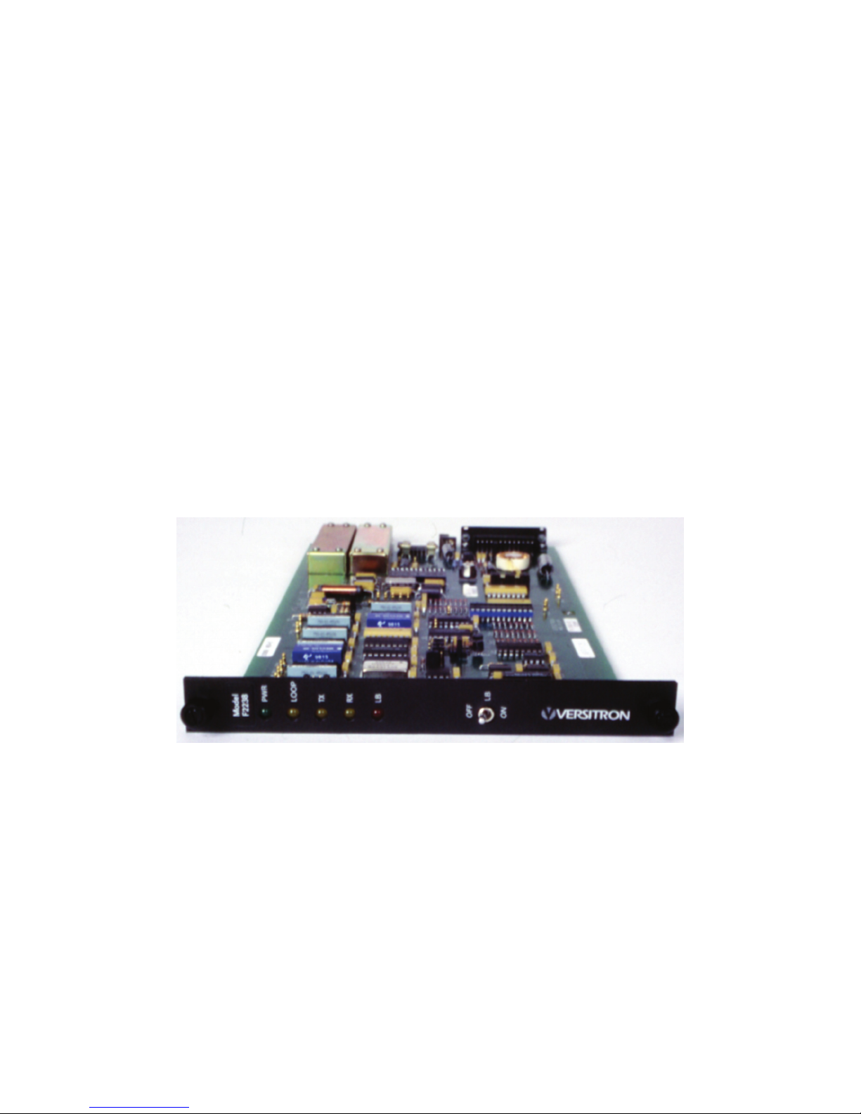
1.2.2 Physical Characteristics
Model F22XX modems measure 7 x 1 x 11 in. WxHxL (17.8 x 2.5 x 27.9 cm). They are
designed to be mounted in VERSITRON’s FOM II Series HF enclosures and chassis (see Table
1). Model HF-1 (single card) desktop enclosures are available for standalone applications.
Standard 19" rack mountable options include models HF-2SS (2-slot) and HF-20A (20-slot)
chassis. Each modem installed in models HF-1 or HF-2SS requires its own VAC to VDC power
adapter. Each power adapter uses the one-pin connector on the back of the modem for power
input. (Customer provided power may be supplied to the modem using the same one-pin
connector.) When installed into the HF-20A chassis model AC300WR power supply is used to
provide power to the chassis and to the modems. Power is provided from the AC300WR power
supply to the HF-20A chassis via model HF-CA3 power interface cable where it is then
distributed to any FOM II Series modem installed in the chassis. Power redundany is included
with the AC300WR power supply with two separate AC input cables provided for power input
from separate VAC sources. The RS-530 copper interface is a female DB25 connector and is
located on the back of the modem. The fiber optic interface, also located on the back of the
modem, consists of two ST connectors (one transmit; one receive). Model F22XX Modems
have five indicator LEDs: power on (PWR), loop indicator (LOOP), transmit data present (TX),
receive data present (RX), and loopback mode indicator (LB).
FIGURE 1. OVERALL VIEW, F22XX MODEMS
2 www.versitron.com
Page 7

Receive Data (A)
Receive Data (B)
Receive Clock (A)
Receive Clock (B)
Transmit Data (A)
Transmit Data (B)
Terminal Timing (A)
Terminal Timing (B)
Signal Ground
Data Set Ready (A)*
Data Set Ready
Data Terminal Ready (A)**
Data Terminal Ready (B)**
Carrier Detect (A)*
Carrier Detect (B)*
Frame Ground
LOCAL MODEM
* Produced by local modem, not received from remote modem.
** Signal not physically passed, used to control signal flow through local modem.
<—
<—
<—
<—
—>
—>
—>
—>
<—>
<—
<—
—>
—>
<—
<—
<—>
3 2
16 14
17 24
9 11
2 3
14 16
24 17
11
7 Fiber cable 7
6 6
22 22
20
23 23
8 8
10 10
1 1
DCE
<—>
DCE
9
20
<—
<—
<—
<—
—>
—>
—>
—>
<—>
—>
—>
<—
<—
—>
—>
<—>
Transmit Data (A)
Transmit Data (B)
Terminal Timing (A)
Terminal Timing (B)
Receive Data (A)
Receive Data (B)
Receive Clock (A)
Receive Clock (B)
Signal Ground
Data Set Ready (A)*
Data Set Ready (B)*
Data Terminal Ready (A)**
Data Terminal Ready (B)**
Carrier Detect (A)*
Carrier Detect (B)*
Frame Ground
REMOTE MODEM
FIGURE 2. F22XX MODEM LINK CONFIGURATION
Model / Part
Number
HF-1* / 19052
HF-2SS / 19629
HF-20A / 32406
Dimensions Description Power Supply Required
7.1 in. wide (18.0 cm) x
1.3 in. high (3.3 cm) x
11.6 in. deep (29.5 cm)
19.0 in. wide (48.3 cm) x
1.7 in. high (4.3 cm) x
13.8 in. deep (35.1 cm)
19.0 in. wide (48.3 cm) x
7.1 in. high (18.0 cm) x
11.6 in. deep (29.5 cm)
Single Card
Standalone Enclosure
2-Slot
Rack Mount Chassis
20-Slot
Rack Mount Chassis
PSAC15 / LTWPD1215PLX (US)
PSAC09 / LTWPD1210EPL (VDE)
PSAC15 / LTWPD1215PLX (US)
PSAC09 / LTWPD1210EPL (VDE)
AC300WR / 32410 (Universal)
* One Power Adapter per Modem is required when installed in these Models.
TABLE 1. ENCLOSURES / CHASSIS
3 www.versitron.com
Page 8

1.3 SPECIFICATIONS
Data Rate: Any data rate from 250 Bps to 10.0 Mbps, synchronous; 100 Kbps, asynchronous.
Operating Mode: Simplex, Half or Full duplex operation over fiber optic cable pair.
Optical Interface: ST connectors.
Digital Interface: Signal levels and format conform to EIA RS-530 (synchronous and
asynchronous) and MIL-STD 188-114 Balanced and Unbalanced.
Electrical Interface: Female DB25 (DCE) connector.
Bit Error Rate: Better than 10-9.
MTBF: 96,428 hrs.
Dimensions: 7 x 1 x 11 in. WxHxL (17.8 x 2.5 x 27.9 cm).
Weight: 12.0 oz. (0.34 kg).
Power Requirements: 12 VDC @ 1.5A, 18 watts; optional VAC to VDC wall transformer:
(VERSITRON Model PSAC15, 120 VAC ~ 60 Hz to 12 VDC, 1.5A)
(VERSITRON Model PSAC09, 230 VAC ~ 50 Hz to 12 VDC, 1A)
Environment: 0° to +50° C (32° to +122° F) operating temperature; up to 95% relative
humidity (non-condensing); up to 10,000 feet altitude; storage temperature -40° to +70° C.
Model F2238 F2240 F2245
Connector
Wavelength
Link Budget*
Maximum
Range*
Fiber Cables
(1.24 mi./6,560 ft)
50 or 62.5/125 µM
ST ST ST
850 nm
Multimode
1300 nm
Multimode
1300 nm
Single Mode
18 ± 1 dB 16 ± 1 dB 22 ± 1 dB
2 Km
(3.7 mi./19,680 ft)
100/140 µM
6 Km
15 Km
(9.3 mi./49,100 ft)
62.5/125 µM 8 or 9 or 10/125 µM
*Note: Multimode tests were performed on 62.5/125 μM fiber optic cable.
Single Mode tests were performed on 9/125 μM fiber optic cable.
4 www.versitron.com
Page 9
SECTION 2
INSTALLATION
2.1 GENERAL
This section contains information on the installation and initial checkout of the Model
F22XX modems. Paragraph 2.2 contains general information on site selection and mounting.
Paragraphs 2.3 through 2.6 contain detailed instructions for connecting F22XX modems and
selecting the available options. Paragraph 2.7 contains initial checkout procedures.
2.2 SITE SELECTION AND MOUNTING
The Model F22XX modems are designed to connect directly to the serial port (DB25
Connector) of terminal equipment with a customer-supplied cable. Mounting options include
single card (HF-1) standalone enclosures and 2-slot (HF-2SS) or 20-slot (HF-20A) rack mount
chassis.
2.3 POWER REQUIREMENTS
Model F22XX modems operate from an AC power source or a DC power source with a DC
voltage of +12 VDC, 1.5A. The power supplies used when installed in a HF-1 enclosure or HF2SS chassis are VERSITRON Model PSAC15 (US) providing +12 VDC, 1.5A or PSAC09
(European) providing +12 VDC, 1A. Connect the power adapter to the F22XX modem before
inserting its plug into an AC power source. No special tools are required. DC power may be
used instead of an AC adapter, if available. This requires a 2.5 mm socket with positive on the
center and common on the concentric, and providing +12 VDC, 1.5A. When modem
installations utilize the Model HF-20A 20-slot chassis the AC300WR Power Supply / System
Monitor is used to provide power to all modems installed. The AC300WR is designed with
power redundancy and requires one unit of rack space above the HF-20A.
2.4 SWITCH SETTINGS
2.4.1 Polarity Straps
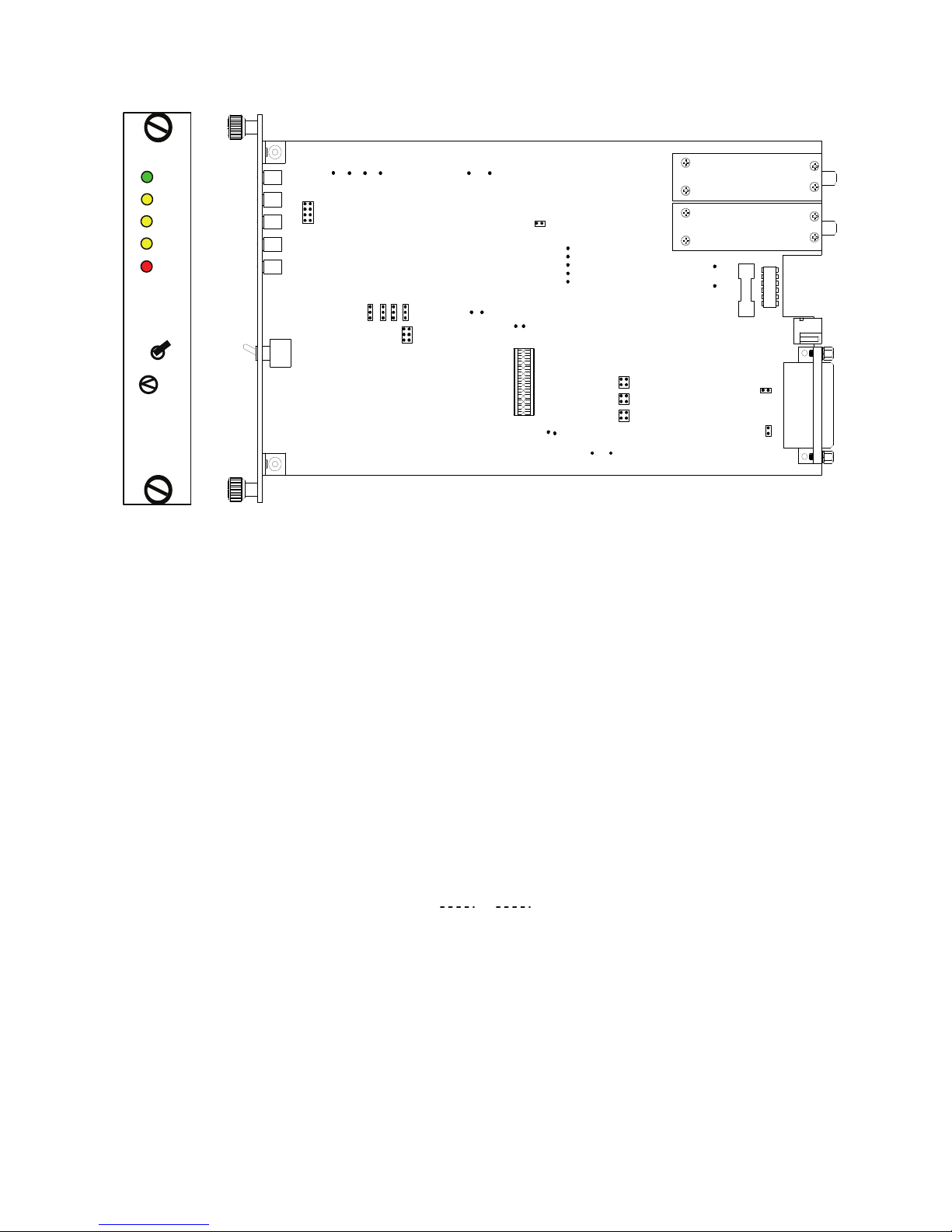
The input/output polarity straps should be set as specified in Table 2. The locations of the
jumpers and test points on the F22XX circuit board are shown in Figure 3.
I/O
CH. 1 (TX DATA) INPUT JP6 A: 3-4, B: 1-2 A: 1-3, B: 2-4
CH. 2 (TX CLOCK) INPUT JP8 A: 3-4, B: 1-2 A: 1-3, B: 2-4
DTR INPUT JP10 A: 3-4, B: 1-2 A: 1-3, B: 2-4
CH. 1 (RX DATA) OUTPUT JP4 2-3 1-2
CH. 2 (RX CLOCK) OUTPUT JP5 2-3 1-2
DCD/DSR OUTPUT JP2 1-2 2-3
LOOPBACK CIRCUIT JP12 OPEN - ENABLED 1-2 - DISABLED
JUMPER
NONINVERTED
(TRUE) POLARITY
INVERTED
POLARITY
TABLE 2. F22XX MODEM JUMPER SETTINGS
5 www.versitron.com
Page 10
Model
F2238
PWR
LOOP
TX
RX
LB
OFF
LB
ON
VERSITRON
DS1
DS2
DS3
DS4
DS5
JP13
1
SW1
TP11 TP7TP12
TP13
2
8
TP9
TP10GND
11
JP2
JP4
JP3
1 1
JP5
12
6
JP1
TP2
TP1
TP3
TP15
GND
JP11
+12V
JP12
GND
TP17 TP18
-12V
TP8
TP14
TP5
TP4
TP6
TP19
GND
JP6
JP10
JP8
TP20
+5V
1 2
112
RX
TX
F1
TP16
-5V
TP21
4
2
4
4
GND
JP9
JP7
P1
J4
J1
FIGURE 3. F22XX MODEM JUMPER AND TEST POINT LOCATIONS
2.4.2 Jumpers for Input Impedance Selection
Channel 1 (Transmit Data) and Channel 2 (Synchronous Transmit Clock or Asynchronous
Data #2) will be set for high impedance when jumpers JP7 and JP9 are not inserted. If JP7 and
JP9 are present, the input impedance is 100 ohm. The 100 ohm termination is not available on
the DTR input.
2.4.3 Jumpers for Transmit Clock Selection
The transmitter operating mode is controlled by jumper JP1. For automatic, rate-dependent
selection of transmitted synchronous clock and data, set JP1 = 3-4. To have the input data
stream synchronized to the internal 10 MHz clock while being processed ("forced sync"), set JP1
= 1-2. For fixed over-sampling of asynchronous data ("forced async"), set JP1 = 5-6. On the
circuit board, pins 1, 3, and 5 are tied together, so the jumper appears as follows:
1o 3o 5o
2o 4o 6o
2.4.4 Jumpers for Receive Clock Selection
For automatic mode (receiver tracking transmitter, full duplex operation) receive clock and
data, set JP3 = 2-3 and JP13 = 1-2, 7-8. For forced synchronous mode (data clocked by internal
10 MHz clock), set JP3 = 2-3 and JP13 = 5-6, 7-8. For forced asynchronous mode, if the
receiver is being used with no transmit clock, or for two asynchronous data channels, set JP3 =
1-2 and JP13 = 1-2, 7-8.
6 www.versitron.com
Page 11

2.4.5 Settings for Balanced/Unbalanced Outputs
The conversion from Balanced to Unbalanced output data streams is accomplished using
jumper JP11, which is a 24-pin jumper network. For MIL-STD-188-114 Balanced (RS-422
compatible) output, JP11 connects the following pins together: 2-23, 4-21, 6-19, 8-17, 10-15,
and 12-13. When a change to MIL-STD-188-114 Unbalanced (RS-423 compatible) output is
desired, JP11 must be removed, rotated 180 degrees, and reinserted so that the following pins are
connected: 1-24, 3-22, 5-20, 7-18, 9-16, and 11-14.
2.5 Output Connections
The F22XX Modem uses a standard DB25 Female connector for the electrical signal
interface. The pinout for this is given in Table 3.
SIGNAL PIN INTERFACE
TX D (A) 2 INPUT
TX D (B) 14 INPUT
TX CLK (A) 24 INPUT
TX CLK (B) 11 INPUT
DTR (A) 20 INPUT
DTR (B) 23 INPUT
RX D (A) 3 OUTPUT
RX D (B) 16 OUTPUT
RX CLK (A) 17 OUTPUT
RX CLK (B) 9 OUTPUT
DSR (A) 6 OUTPUT
DSR (B) 22 OUTPUT
DCD (A) 8 CONNECTED INTERNALLY TO DSR (A)
DCD (B) 10 CONNECTED INTERNALLY TO DSR (B)
TABLE 3. MODEL F22XX ELECTRICAL SIGNAL INTERFACE (DB25F) PINOUT
2.6 LOOPBACK
The F22XX Modem has a loopback mode to facilitate the testing of the unit in a system
environment. When the Loopback switch on the front panel of the circuit card is in the ON
position, the line encoder is routed directly to the line decoder, and the fiber optic receiver output
is connected directly to the fiber optic transmitter input. This achieves a loopback of the
transmit data to the receive data output, the transmit clock to the receive clock output, the DTR
input to the DCD/DSR output, and the received optical input to the transmit optical output.
Therefore the loopback mode tests virtually 100% of the Modem.
7 www.versitron.com
Page 12

2.7 INITIAL CHECKOUT PROCEDURE
The F22XX Modem contains no power on/off switch. Once properly installed and
powered, the unit is fully operational. The power indicator should remain on as long as power is
supplied to the unit.
Before beginning system operation, to ensure proper installation, verify that:
1. The power plug is seated fully into the Modem or seated firmly in the rack-mount chassis.
2. The fiber optic cable is crossed transmit to receive from unit one to unit two and vice versa.
3. The LOOP LED illuminates when a link is established to the remote optical receiver of the
F22XX. Note that the LOOP LED will illuminate regardless if there is data flowing to indicate a
valid link between the two modems over fiber optic cable.
4. The jumper settings for the circuit configuration are correct (e.g. non-inverted/inverted signal
polarity, clock selection, balanced/unbalanced outputs).
If a malfunction is detected during the initial checkout procedure, refer to Chapter 5 for
information on isolating the malfunction in the unit.
8 www.versitron.com
Page 13

SECTION 3
OPERATION
3.1 INTRODUCTION
This chapter contains a description of the operating controls and indicators associated with
the Model F22XX FOM II series Modems. Since the Model F22XX is designed for continuous
and uninterrupted operation, there are no changes required during operation. Once powered up
the Model F22XX should remain in service as long as required.
3.2 STATUS INDICATORS
Five LED indicators on the Model F22XX FOM II products provide the operational status
of the unit. When illuminated, the green power (PWR) LED indicates that all DC power supply
voltages are present. The next indicator, labeled loop (LOOP) will illuminate when the optical
receiver detects an input. The transmit data (TX) and receive data (RX) indicators show the
presence of data activity. The red LED for loopback (LB) indicates that the circuit board is in
loopback mode when illuminated. There is no audible alarm with the F22XX Modems.
3.3 BIT RATE MONITOR
The bit-rate-monitor circuit measures the transmit clock period and is used to control the
code time base when the Modem is in the automatic mode. At low clock rates, or when no clock
is present, the unit selects an internal 10 MHz oscillator as the code time base. This high
sampling rate minimizes jitter caused by sampling within the transmit circuit. At higher clock
rates, the transmit clock itself is selected as the code time base. This has the advantage that the
code is synchronous with the transmitted data, so there is no sampling-induced jitter.
When the input data rate increases from below 50 Kbps, the bit-rate-monitor circuit will
switch from the 10 MHz oscillator to the transmit clock at a data rate of about 120 Kbps. It will
switch in the opposite direction when the data rate falls below about 60 Kbps. The hysteresis in
the switching circuit protects against the modem switching time bases incorrectly if operating
close to the switching threshold.
3.4 CLOCK SELECT OPTIONS
The only controls with the Model F22XX FOM II Series Modems are those jumpers that
configure the operation in one of three modes: Automatic, Forced Synchronous, and Forced
Asynchronous. The Automatic mode is appropriate for use with full duplex data transmission.
One of the two Forced modes should be used if the transmit and received sections of the circuit
board are operated independently of each other. The jumper settings are described in Section 2.4
and selection is normally done at the time of installation. Further changes are not required
unless the overall system requirements change.
SECTION 4
9 www.versitron.com
Page 14

THEORY OF OPERATION
4.1 INTRODUCTION
Basic operation of the Model F22XX is similar to a two-channel, full duplex multiplexer.
The first channel is used for high-speed synchronous data. The second channel is used for
transmit clock, or for an asynchronous second data channel. Both channels may be used for lowspeed (less than 100 Kbps), asynchronous operation.
The first of the three operating modes of the F22XX Modems permits data transparency.
In the Automatic mode a data rate from 250 Bps to 10 Mbps is accepted and the data rate may be
variable, as is sometimes seen in high-speed telemetry systems. An internal bit rate monitor
circuit selects the source of the transmit clock. At clock rates of less than 100 Kbps, or when no
external clock is present, an internal 10 MHz reference signal is utilized as the clock. This
assures a sufficiently large number of samples for minimum end-to-end timing jitter. The actual
clock signal is used at clock frequencies greater than 100 kHz.
If a fully transparent synchronous link is not required, the clock and control paths may be
used as additional asynchronous data paths. The transmit and receive clock inputs will handle
data rates from 0 to 76.8 Kbps asynchronously.
SECTION 5
MAINTENANCE AND TROUBLESHOOTING
10 www.versitron.com
Page 15

5.1 INTRODUCTION
This chapter contains general information designed to isolate a malfunction in the Model
F22XX to a replaceable unit. These units are not equipped with redundancy. Therefore, a
failure in one of these units would interrupt service.
5.2 FAULT ISOLATION
The steps in Table 4 should be taken to check a non-operating Modem.
STATUS INDICATOR PROBABLE CAUSE CORRECTIVE ACTION
POWER (PWR) LED is off. No AC power. Check that both ends of the Transformer are
connected.
Blown Fuse. Replace with 250V 1A slo-blo fuse.
Other power supply circuit problem. Contact VERSITRON for assistance.
LOOP (LOOP) LED is off
or not responding.
2. Check that the remote unit power is on
3. Measure the optical levels on both ends
4. Contact VERSITRON for assistance.
DATA (TX or RX) LEDs
are off or not responding.
No input on the electrical interface
DATA AND CLOCK
Signal Inverted.
Inverted input on the electrical interface
Incorrect optical signal level received at
receiver input.
Jumpers in wrong position. Check that the jumper is set for the correct
connector.
Jumpers in wrong position. Check that the jumper is set for the correct
connector.
1. Check that fiber optic cable is properly
connected to RX connector.
and the TX fiber optic connector is
connected properly.
(if possible) in order to check the optical
link.
electrical interface.
Check that the interface connector is
connected securely.
electrical interface.
Check that the interface connector is wired
per interface standard RS-530.
TABLE 4. NON-OPERATIONAL INDICATORS
11 www.versitron.com
 Loading...