

Versiton BHR40-V851 Manual Manual
9. Power cable or videocable should be always loose.
Donot keep the cables tight or twisted.
10. Do not leave the unit along withan unstable stand or table.
11. Please use the camera unitwithin giventemperature andelectricity limit.
12. Please make sure thatinstallation should be doneby qualifiedservice
person only.
13. Donotdisassemble theunitby yourself. When there isproblemwith
the unitplease contact after-saleservice center or the shop where
you bought.
1. Ma
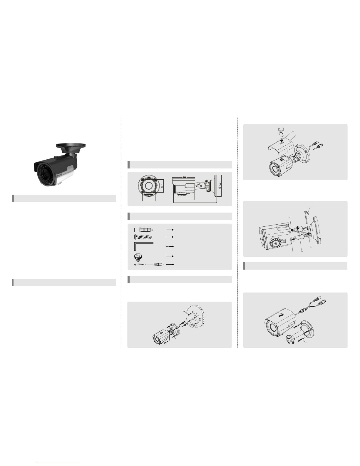
ke a hole of Ø 25mm indiameter for passing cable.
2. Drill four holes on thewall or ceiling and insert theanchors.
3. Arrange the cables and fix the screws.
ACCESSORIES
DIMENSION
4. Attach the sunvisor and fix the sunv isor fixing bolt.
5.Loosen the bolt A, C-1and C-2by using the 3mmwrench included.
6. Face the direction ofthe camera to monitor.
7. Tighen the bolt A, B, C- 1, C-2 to complete adjustment.
1. Attach the bracket to the camera's bottom hole tightly.(In case of
installing the camera on the ceiling, attach the bracket to the
sunvisor fixing bolt hole on top of the camera.)
2.Fix the cameraandbracket on the wall or ceiling.
1. Newgener
ation,new technology DSP adopted.
2. This camera is incredibly flexibletoinstall with its 3-axiscameraconstruction,which makesthe camera ceiling,wall or slopemountable.
3. This product is weather-proofto resist rain, snow and other weather
factors(IP66).
4. 40M range visible in totaldarkness with 40pcs of IR LEDs.(Indoor)
5. Supreme Resolution(700 TV-Line)
6. Day & Night function
7. Support 4 different privacy zone
8. DWDR(Digital Wide Dynamic Range)
9.Mul
ti function: High LightMask,Lens ShadingCompensation,Motion
Detection
10. Dynamic IR : When IR LED is turned on in B/W, the objects can be
clearly identified due to the function that decreasesscreen saturation
ofobjectswithin a shortdistance.
11. Multi-language full OSDsupport
1. Please study the instruction manual before your applications and
keep it for your future reference.
2. Donot flash LED lightdirectly on theeyes when LEDs are on.
3. Do notinstall the camer
a on a unstable surface.
Itwill cause falling or other hazards.
4. Do not use improper power, it could cause fire or electric shock.
(Use the AC adaptor 12V DC regulated,1A)
5. Do not disassemble or re-model the camera, it could cause fire,
electric shock or other hazards.
6. Stop using the camera when you find a malfunction like smoke or
unusualheat, it could cause fire or electric shock.
7. Due to the possibility of water leakage, do not cut or peel off the
cable.In case you cut or
peel off thecable, the warranty will be void.
8. Do not adhere dangerous articlesto the camera.
CAUTION
FEATURE
IR WATERPROOF CAMERA
MANUAL
HOW TO INSTALL(Built-in brackettype)
HOW TO INSTALL(Stand bracket type - Option)
SCREW, 3EA
WRENCH
BOLTA
BOLT C-2
BOLTC-1
BOLTB
BOLT
SUNVISOR
207
102
61.5
Ø6
Ø 25
ANCHOR 6x30, 4EA
SCREW Tp14x35,4EA
ANCHOR 6x30, 4EA
SCREW 4x35 TP1PANSUS,4EA
WRENCH 3mm L TYPE, 1EA
SUNVISOR BOLT, 1EA
Extra videooutput cable for installation,
1EA(option)
BHR40-V851
Aurora
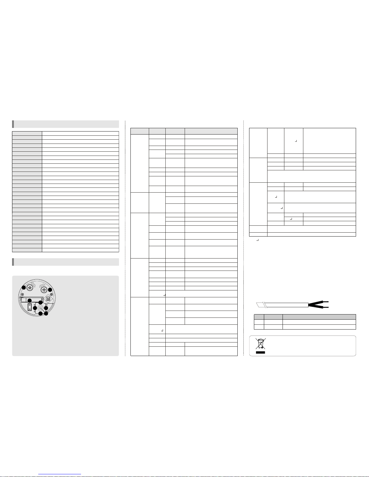
FUNCTION SETTING
1. How to use the jog lever
SPECIFICATION
※All specification is subject to change without notice to improve the quality.
1/3"SONY SUPERHAD CCD
768(H)X 494(V)PIXEL(NTSC),752(H)X 582(V) PIXEL(PAL)
6.35 (H) X7.4 (V)(NTSC), 6.5 (H)X 6.25 (V)(PAL)
2:1Interlace
Internal
700 TV-Line
48dBor More(AGC OFF)
1.0 Vp-p(Sync. Negative) Termination 75
0.1Lux(F/1.2),0Lux(40M Range with 40pcs LED) -Indoor
γ
= 0.45 typ.(0.45,0.6,1.0, user)
Yes(MultiLanguage)
ATW(2,500°K ~ 9,500°K)/MANUAL/AWC
1/60(1/50)~ 1/100,0
00sec
BLC,DWDR, HLC(ON/OFF)
LOW/MIDDLE/HIGH/OFF
ON/OFF(64 Block)
ON/OFF(4 Zone)
ON/OFF
AUTO, COLOR, B/W(Electronic)
40pcs, DynamicIR
ON/OFF
RS-485(Protocol :PelcoD,PelcoP)
Vari-focal auto iris lens
12V DC± 10%(24V AC: option)
Max.850mA(at12V DC,24V AC) :LED ON
-10℃ ~ 50℃
-20℃~ 60℃
61.5(W) X61.5(H)X 102(D)mm
Approx. 900g
Ⅱ
㎛ ㎛ ㎛ ㎛
Ω
ModelNo.
Image Sensor
Effective Pixel
CellSize
Scanning System
Sync.Type
Resolution
S/N
VideoOutput
OSD
AGC
Min.Illumination
Gam
ma
White Balance
Shutter Speed
Backlight
Motion Detection
Privacy Zone
Mirror
Day & Night
LEDBrightness
DIS
Communication(option)
Lens
Power Supply
CurrentConsumption
Operation Temp.
Preservation Temp.
Dimension
Weight
Display each privacy mask or not. Press the
enter button to move into the privacy mask
settingsection, whenever you press the enter
button,the mask color is changed.When the
mask color is red you can adjustthe size by
up,down, leftand rightbutton.
When themask
color is blue you can setthe position of mask
by up, down, left and right button. Press the
enter buttonfor a few secondto escape
Select mask color
SelectthecameraIDfor RS-485communication
Select baud rate
Select protocol
Select language
Display the camera IDon the screen
InternalSync with 12V DCpower
Line-Lock(Not available)
Notavailable
OFF, ON
BLACK, GRAY…
1~ 255
2400 ~ 9600
ENGLISH, …
OFF, ON
INT
L/L
0 ~ 255
MASK
1, 2,3, 4
CAMID
BAUDRATE
PROTOCOL
LANGUAGE
SYNC
EDIT
POSITION
VPHASE
3. How to control through RS-485 communication(Option)
4. Cable array(Option)
1) Match the camera with controller'sID,baudrate and protocol
2)Up, Down, Left and right ofJog lever is same as Up,Down,Left and
right ofRS-485 controller
3)Enter of Jog lever isthesameasmenukey orIRIS open keyofRS-485
controller
4) Return to previous menu from motion detection setting section and
privacy mask setting section :Iris close orIrisopen for a few second.
Or pressthe buttona
s Up Right Down Left successively→ → →
2. OSD menu structure
Ifthe product is to be put out of operation definitively,
take it to a local recycling plantfor a disposal which
is not harmful to the environment.
Function
RX +
RX -
Remark
RS-485A
RS-485B
No.
A
B
A :ORANGE(RX +)
B : WHITE(RX -)
6.PRIVACY
ZONE
MANUAL,DC
0 ~ 100
0 ~ 20
AUTO
OFF, LOW,
MIDDLE, HIGH
OFF, ON
OFF, ON,
AUTO
0 ~ 100
ATW
MANUAL
AWC
AUTO
COLOR
B&W
OFF, ON
85 ~ 170
50 ~ 135
3 ~ 15
OFF, ON
OFF, ON
0 ~ 50
OFF, ON
0 ~ 50
0 ~ 200
0 ~ 200
OFF, ON
NONE
MESSAGE
MASK
0 ~ 255
1~ 15
Fixed focallens or Vari-focal auto iris lens
In case of manual lens selection, adjust the
brightness
Incase ofDC lensselection,adjustthe brightness
Shutterspeed autoadjustable
Select shutter speed manually
Determines that use the AGC function or not
and AGC lev
el selectable(You cannot use the
Auto D&N change mode when AGC is off)
DigitalWideDynamic Range
BLCfunction
High Light Mask function
In case ofAUTO mode, the function will off in
daytimeand onat night
According tothe threshold value, thecamera
will recognize asHighlightor not.
Color temperature2500 ~ 9500°K
Adjust the Red or Blue values toshift the color
oftheobject
Move the camera lens toward to white paper
then press the set button to find the optimal
white balancefo
r currentenvironment
Auto day&nightswitchingmode
Fixed atcolor
Fixed atB/W
Determines whetherto transmitthe burstsignal
ornotin B/W mode
You can select brightness of illumination about
changingthe day ↔ night mode
You can select the duration time about chainging
the day ↔ nightmode
When IR LED is turned on in B/W, the objects
can be clearly identified due to the function
that decreases screen saturation of objects
within ashortdistance.
Seta horizontal imageinver
sion
Sharpness adjustable
Gamma adjustable
Determines whether tousethe brightness com-
pensationoffour lens' corners(LSC) ornot
The LSC level selectable
Adjust Red tone of the image
Adjust Blue tone of the image
Determineswhether to use themotiondetection
functionor not
Nodisplay on the screen though movement is
detected
The words 'MOTION' appear on the screen
whenmovementis detected
Motion detection area appear on the screen
whenmovementis detected
Motionde
tection sensitivity
Setthe duration ofoutside alarm. If the way of
display is message, it means display time of
message
LENS
E.SHUTTER
AGC
DWDR
BLC
HLC
AWB MODE
D&NMODE
DYNAMICIR
MIRROR
SHARPNESS
GAMMA
LSC
R-Y GAIN
B-Y GAIN
MOTION
BRIGHT
DCLEVEL
HLC THR
BURST
DELAY TIME
LSC LEVEL
DISPLAY
SET
WINDOW
ALL SET
SENSITIVITY
HOLD TIME
Fun ction
setting menu
Select menu ContentsSub menu
1/60(1/50)~1/100,000
BW COLOR→
COLOR BW→
0.45, 0.6,1,USER
ALL CLEAR↓
1. EXPOSURE
3.DAY&NIGHT
4.IMAGEA DJ.
2.WHITE
BALANCE
5. ALARM
PATTERN
GENERATOR
ㆍThe ' ' icon appearedwith desired function,press the setbutton tomove sub menu.
ㆍThe'- --' icon appeared with function that is unavailable according to function setting.
OFF, LOW,MIDDLE,HIGH
MASK COLOR
PELCO-D, PELCO-P
NAMEDISPLAY
10. EXIT
8. SPECIAL
9. FACTORY
SET
7.COMMUNICATION
(option)
To reset your camera to factory defaultcondition
Notice :Lens,communication andlanguage isnotchanged
Savethe value and then restart
※If you change the COMMUNICATION value through RS-485, you might not
controlthe camera due tounmatched value(If your camera isout of working
due toabove reason, change your controller's valueor waita fewminu
te till
close the menu,it will beback to previoussetting value)
Press the enter button to move into the name setting section.
You can choose the letter by using up and down button and
move next letter by using left and right button. Press the
buttonfor afew secondto move out
enter
Press the button to move into theposition setting section.
You canmove the camera IDto your wanted position by using
up,down,left andrightbutton
enter
Test signal. Press the enter button, color bar
appeared on the
screen and press anykey toreturn tomenu
Press the button to move into the motion detection area
section to the 64 areas.Press the button for a few
second to move out
Press the button to selectall area
Press the button to remove all area
enter
enter enter
enter
enter
①ENTER :
② UP, ③DOWN :
④LEFT, ⑤ RIGHT :
⑥ FOCUS, ⑦ZOOM :
⑧EXT.V IDEO :
ㆍPush the lever : Used to access the
menu and confirm selection.
ㆍPush theleverforonesecond : Used
to return to previous menu from the
motion detection setting section or
privacy mask settingsection.
Used to move the
cursor to upor down.
Used to move the
cursor to leftor rightand changethe
value.
Use a '+' type
driver for adjusting zoom and focus.
(In case of operation Focus/Zoom,
don'tput stress excessively.
)
Extra video output terminal for installation.The cable
is option.
*OSD menu& Focus/Zoom
adjustmentdirection
1. Unfasten the screw of the
bottomdoor
2.Adjustthe jog lever& Focus
/Zoomtrimmers
3. Tighten the screw of the
bottomdoor
F
EXT.VIDEO
Z
7
6
8
2
5
13
4
BHR40-V851
 Loading...