

Page 1
PPrrooffeessssiioonnaallAAuuddiio
o
EN - User Manual
IT - Manuale Utente
DE - Benutzerhandbuch
Ver. 1 .0
EDGE
Active Speakers
500
Page 2
Page 3

EDGE 500
- User Manual
CONTENTS
Important notes ........................................................................................................... 1
Overview ..................................................................................................................... 2
Controls and connections ............................................................................................ 3
Connection examples .................................................................................................. 5
Components, configuration and performances............................................................ 8
Placement ................................................................................................................... 9
Usage suggestions .................................................................................................... 12
Technical specifications ............................................................................................. 13
Block diagram............................................................................................................ 14
IMPORTANT NOTES
LOOKING AFTER THE PRODUCT
• Never apply excessive force to the structures or controls (knobs, switches).
• Do not stress the speaker in transit or during use.
• Do not place the device close to heat sources, in damp or dusty places or close to
strong magnetic fields.
• When possible, do not place the speaker close to units which generate strong
interference, such as radio and TV sets, monitors, etc.
• Never insert objects or liquids of any kind inside the device, for any reason.
• Clean using a soft brush or an air jet only; never use detergents, solvents or alcohol.
• When disconnecting cables from sockets, always take hold of them by the connector
and not by the cable itself, and when winding take care to avoid knots or twisting.
• Do not expose the speaker to direct sunlight.
CONNECTING TO THE MAINS
• To avoid the risk of electric shock, do not make connections with wet hands.
• Make sure that the mains voltage is the same as that indicated on the control panel.
• Connect the speaker to a mains socket with earth contact.
CONNECTING TO A MIXER
• Always use good quality screened cables.
• Before making the connections, check that all the speakers you are about to connect
are switched off. You will avoid noisy, if not hazardous, signal peaks.
IN CASE OF MALFUNCTION
• In case of malfunction, contact only an authorised service centre.
EN - 1
Page 4
User Manual - EDGE 500
PRESENTATION
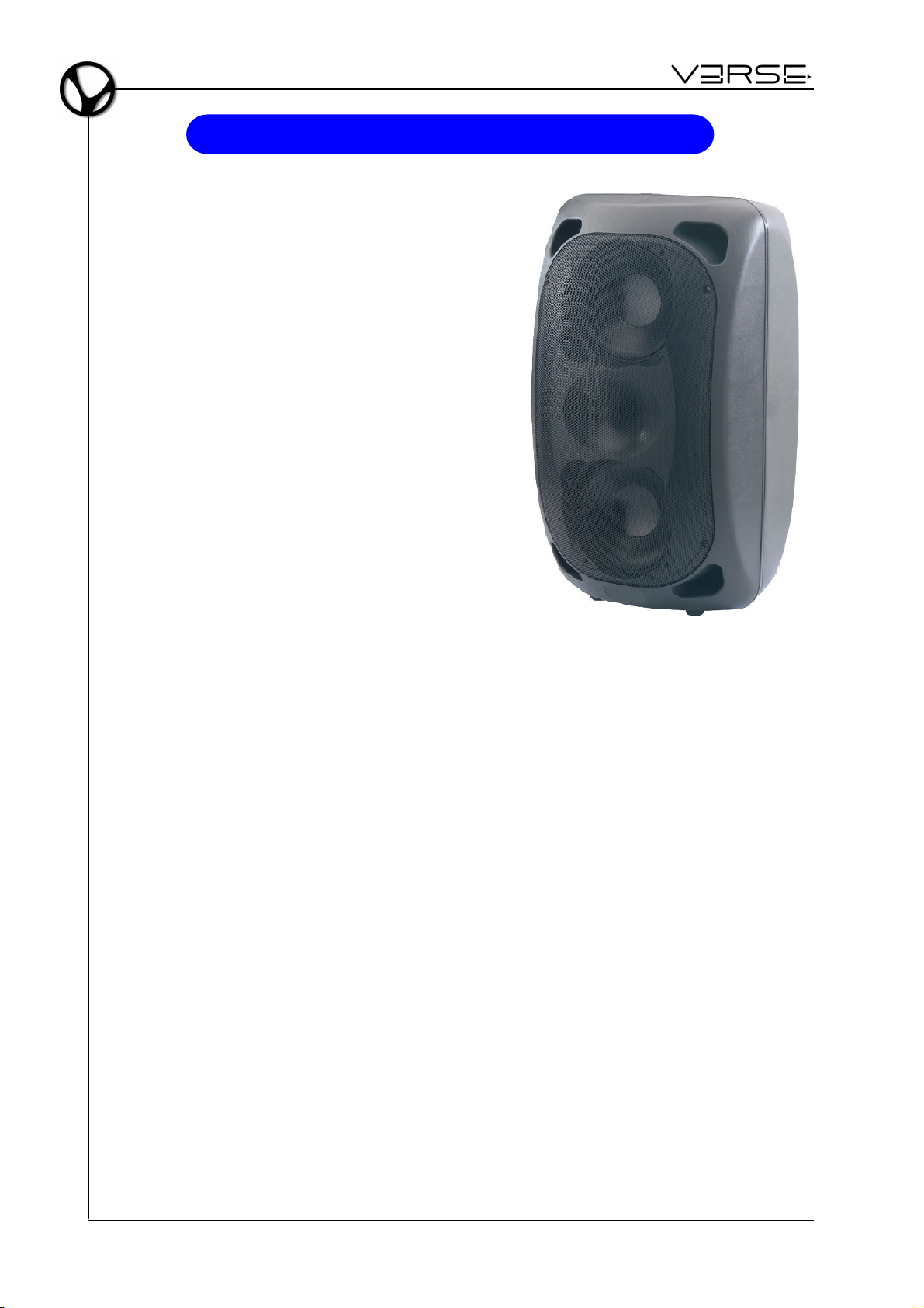
EDGE 500 is an active speaker that combines
technology, experience and good taste in the ideal
combination of sound quality, power and userfriendliness. It is equipped with 2 (two) 8" woofers
custom + 1" compression driver, 2 independent
signal processors for high/low frequencies .
The speaker is backed up by a digital signal
processing chain, 350W+65W biamplification and
meticulous sound engineering which ensures
impeccable results in terms of intelligible sound
reproduction, breadth and constancy of diffusion,
power and amplification precision.
The cabinet, in polypropylene with scratchproof
finish, is attractively styled and designed to make
the speaker easy to use and install in a variety of
positions, both on the ground and suspended.
The EDGE 500 is the ideal solution for all small
and medium-sized sound systems where it is
important to obtain the maximum sound coverage
with the smallest possible number of speakers.
TECHNOLOGY
AMPLIFIERS
The new digital technology totally changed the way a professional audio amplifier is
developed. No other way make possible to give great power and long term reliability.
Remarkable heat reduction and outstanding weight decrease make digital amplifier, that
equip VERSE EDGE 500, efficient, powerful and less heating.
The output stages of the amplifiers typically run at 95% efficiency, dissipating only 5% of
the input energy as heat. Moreover the efficiency doesn't depend on the output level,
and Since standard music has an average power density of 40% of the maximum level,
conventional amplifiers can easily generate 10 times more heat than VERSE ones for
the same volume of sound.
To grant reliability and durability, VERSE amplifiers are provided with short-circuit
protection, thermal protection with fan-speed control (that avoid temperature rising over
60° C) and amplifier disactivation system thus preventing amplifier breakdown if temperature rise to intolerable values. And also: protection circuit to cancel direct current
component, protection from ultrasonic components in input and output.
The I.T.P (Intelligent Thermal Protect) is warranty of perfect-working and long-lasting
speakers.
EN - 2
Page 5
EDGE 500
PROCESSING
The processors include cross-over and pass-band filters, level compressors/limiters,
delay for the phase alignment of the system. The processors work automatically and are
conceived to assure the best condition of playback and safety.
In detail: each one of the two ways has his own limiter wich act on the equalizer section
and not – as usually happens – on the overall level only. This leaves – also when the
limiter acts – the sound nearly unchanged, because only the critic frequency region is
damped.
- User Manual
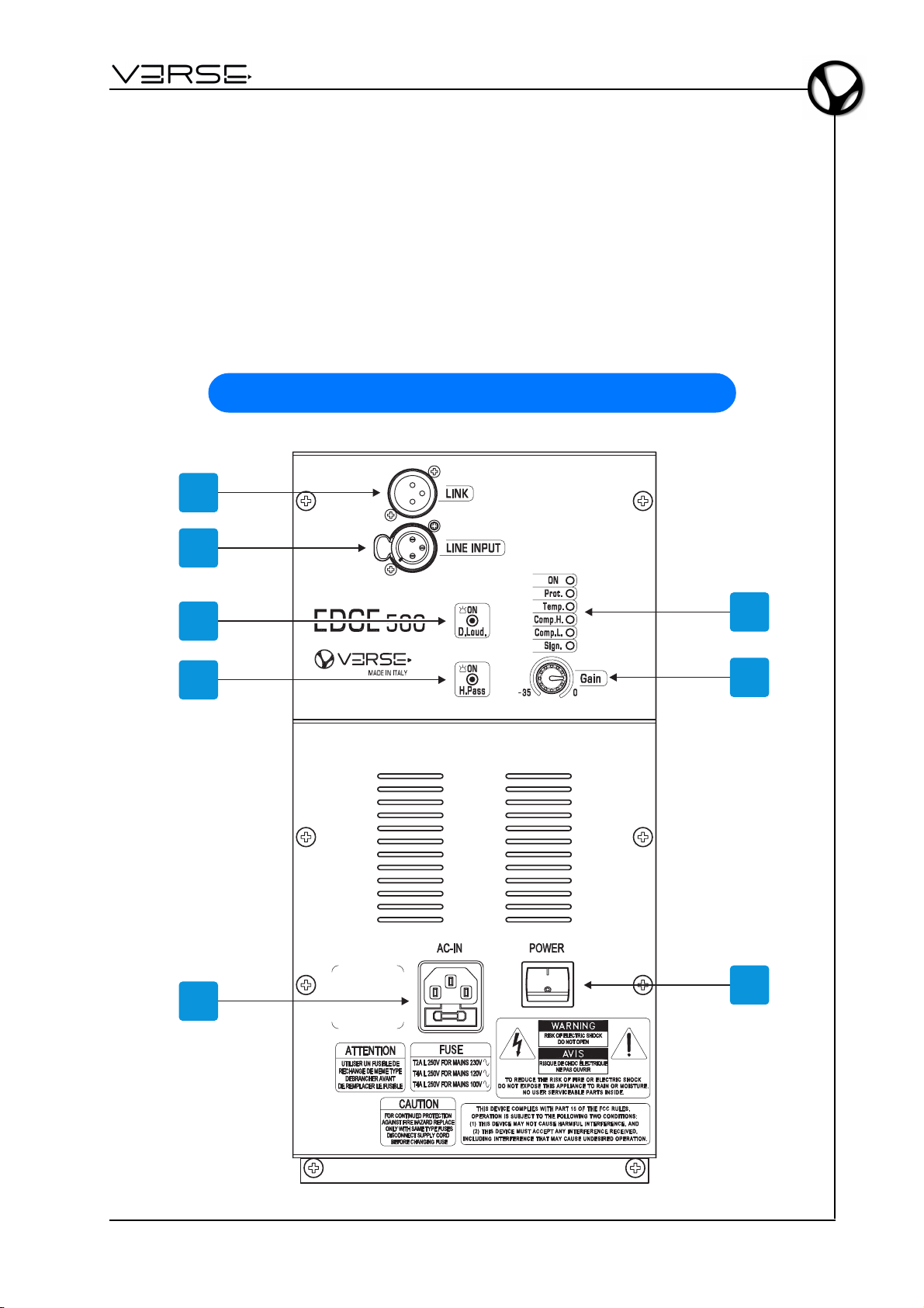
CONTROLS AND CONNECTIONS
1
2
3
4
5
6
7
8
EN - 3
Page 6

User Manual - EDGE 500
1. Link: sends on output the same signal coming from LINE INPUT connector. This
allow the cascade connection of different devices to the same sound source.
2. Line Input: balanced XLR socket for connection of the signal to be amplified.
3. D.Loud.: activates a dynamic equalization of the system, to compensate the natural
sensibility curve of the human ear, which is weaker on low and high frequencies,
when the sound volume is low. The equalization is dynamic, allowing to regulate
continously the amount, according to the signal level, fading away when the volumes
get to the highest levels.
4. H.Pass: activates a High-Pass filter, expressly made to join the speaker together
with a subwoofer. When this filter is turned off, the speaker behaves like a full-range
speaker, while when the filter is activated the speaker behaves like a "satellite" of a
subwoofer.
5. AC-IN: power supply cable socket. The socket is fitted with a fuse in a protected
casing. If the fuse needs changing, it is very important to proceed as follows:
- switch off the device;
- remove the power supply cable;
- access the fuse compartment by opening the cover with a screwdriver;
- replace the fuse with another having exactly the same specifications, T2A L 250V in
230 VAC version or - T4A L 250V in 120 VAC and 100 VAC versions;
- close the cover.
6. LEDs:
- ON: indicates that the speaker is On.
- Prot.: indicates that the internal amplifier switched to protection mode due to a fault
of the amplifier itself or of the connected speakers (please call the technical support).
- Temp.: indicates that the internal amplifier switched to protection mode due to
excessive heating. In this condition, the amplifier supply half the normal power.
Please reduce the input signal to allow the restore of normal load conditions.
- Comp. H.: indicates activity of the High frequency compressor. If the signal passes
over a safety threshold, the compressor guarantees a good quality playback without
acoustic distortion, damping the appropriate signal frequencies. The system operates
in total safety. If the LED is constantly On, there is an excess of signal. In this case,
please reduce the incoming signal level.
- Comp. L.: indicates activity of the Low frequency compressor. If the signal passes
over a safety threshold, the compressor guarantees a good quality playback without
acoustic distortion, damping the appropriate signal frequencies. The system operates
in total safety. If the LED is constantly On, there is an excess of signal. In this case,
please reduce the incoming signal level.
- Sign.: indicates that the signal is present.
7. Gain: to adjust the signal gain in the range from -35dB to 0dB.
8. POWER: switches the power on/off.
EN - 4
Page 7
EDGE 500
G
A
I
N
L
I
N
E
I
M
C
G
A
I
N
S
E
N
S
I
T
I
V
I
T
Y
L
I
N
E
G
A
I
N
L
I
N
E
I
M
C
G
A
I
N
S
E
N
S
I
T
I
V
I
T
Y
L
I
N
E
-10dB
+10-30
-50dB
G
A
I
N
L
I
N
E
I
M
C
G
A
I
N
S
E
N
S
I
T
I
V
I
T
Y
L
I
N
E
-10dB
+10-30
-50dB-10dB
+10-30
-50dB
G
A
I
N
L
I
N
E
I
M
C
G
A
I
N
S
E
N
S
I
T
I
V
I
T
Y
L
I
N
E
G
A
I
N
L
I
N
E
I
M
C
G
A
I
N
S
E
N
S
I
T
I
V
I
T
Y
L
I
N
E
-10dB
+10-30
-50dB
G
A
I
N
L
I
N
E
I
M
C
G
A
I
N
S
E
N
S
I
T
I
V
I
T
Y
L
I
N
E
-10dB
+10-30
-50dB-10dB
+10-30
-50dB
G
A
I
N
L
I
N
E
I
M
C
G
A
I
N
S
E
N
S
I
T
I
V
I
T
Y
L
I
N
E
G
A
I
N
L
I
N
E
I
M
C
G
A
I
N
S
E
N
S
I
T
I
V
I
T
Y
L
I
N
E
-10dB
+10-30
-50dB
G
A
I
N
L
I
N
E
I
M
C
G
A
I
N
S
E
N
S
I
T
I
V
I
T
Y
L
I
N
E
-10dB
+10-30
-50dB-10dB
+10-30
-50dB
G
A
I
N
L
I
N
E
I
M
C
G
A
I
N
S
E
N
S
I
T
I
V
I
T
Y
L
I
N
E
G
A
I
N
L
I
N
E
I
M
C
G
A
I
N
S
E
N
S
I
T
I
V
I
T
Y
L
I
N
E
-10dB
+10-30
-50dB
G
A
I
N
L
I
N
E
I
M
C
G
A
I
N
S
E
N
S
I
T
I
V
I
T
Y
L
I
N
E
-10dB
+10-30
-50dB-10dB
+10-30
-50dB
G
A
I
N
L
I
N
E
I
M
C
G
A
I
N
S
E
N
S
I
T
I
V
I
T
Y
L
I
N
E
G
A
I
N
L
I
N
E
I
M
C
G
A
I
N
S
E
N
S
I
T
I
V
I
T
Y
L
I
N
E
-10dB
+10-30
-50dB
G
A
I
N
L
I
N
E
I
M
C
G
A
I
N
S
E
N
S
I
T
I
V
I
T
Y
L
I
N
E
-10dB
+10-30
-50dB-10dB
+10-30
-50dB
G
A
I
N
L
I
N
E
I
M
C
G
A
I
N
S
E
N
S
I
T
I
V
I
T
Y
L
I
N
E
G
A
I
N
L
I
N
E
I
M
C
G
A
I
N
S
E
N
S
I
T
I
V
I
T
Y
L
I
N
E
-10dB
+10-30
-50dB
G
A
I
N
L
I
N
E
I
M
C
G
A
I
N
S
E
N
S
I
T
I
V
I
T
Y
L
I
N
E
-10dB
+10-30
-50dB-10dB
+10-30
-50dB
G
A
I
N
L
I
N
E
I
M
C
G
A
I
N
S
E
N
S
I
T
I
V
I
T
Y
L
I
N
E
G
A
I
N
L
I
N
E
I
M
C
G
A
I
N
S
E
N
S
I
T
I
V
I
T
Y
L
I
N
E
-10dB
+10-30
-50dB
G
A
I
N
L
I
N
E
I
M
C
G
A
I
N
S
E
N
S
I
T
I
V
I
T
Y
L
I
N
E
-10dB
+10-30
-50dB-10dB
+10-30
-50dB
G
A
I
N
L
I
N
E
I
M
C
G
A
I
N
S
E
N
S
I
T
I
V
I
T
Y
L
I
N
E
G
A
I
N
L
I
N
E
I
M
C
G
A
I
N
S
E
N
S
I
T
I
V
I
T
Y
L
I
N
E
-10dB
+10-30
-50dB
G
A
I
N
L
I
N
E
I
M
C
G
A
I
N
S
E
N
S
I
T
I
V
I
T
Y
L
I
N
E
-10dB
+10-30
-50dB-10dB
+10-30
-50dB
- User Manual
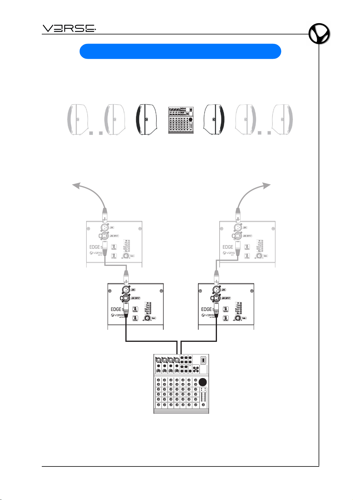
CONNECTION EXAMPLES
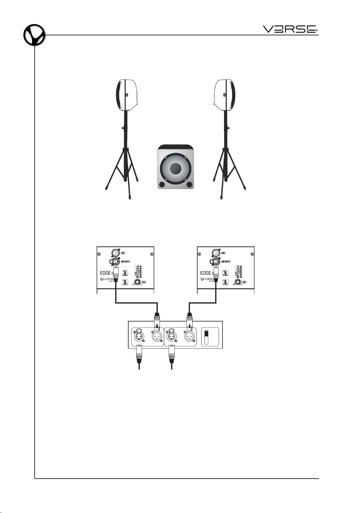
MIXER + 2 (or more) EDGE 500 - STEREO
LEFT RIGHT
Left Out Right Out
MIXER
EN - 5
Page 8
User Manual - EDGE 500
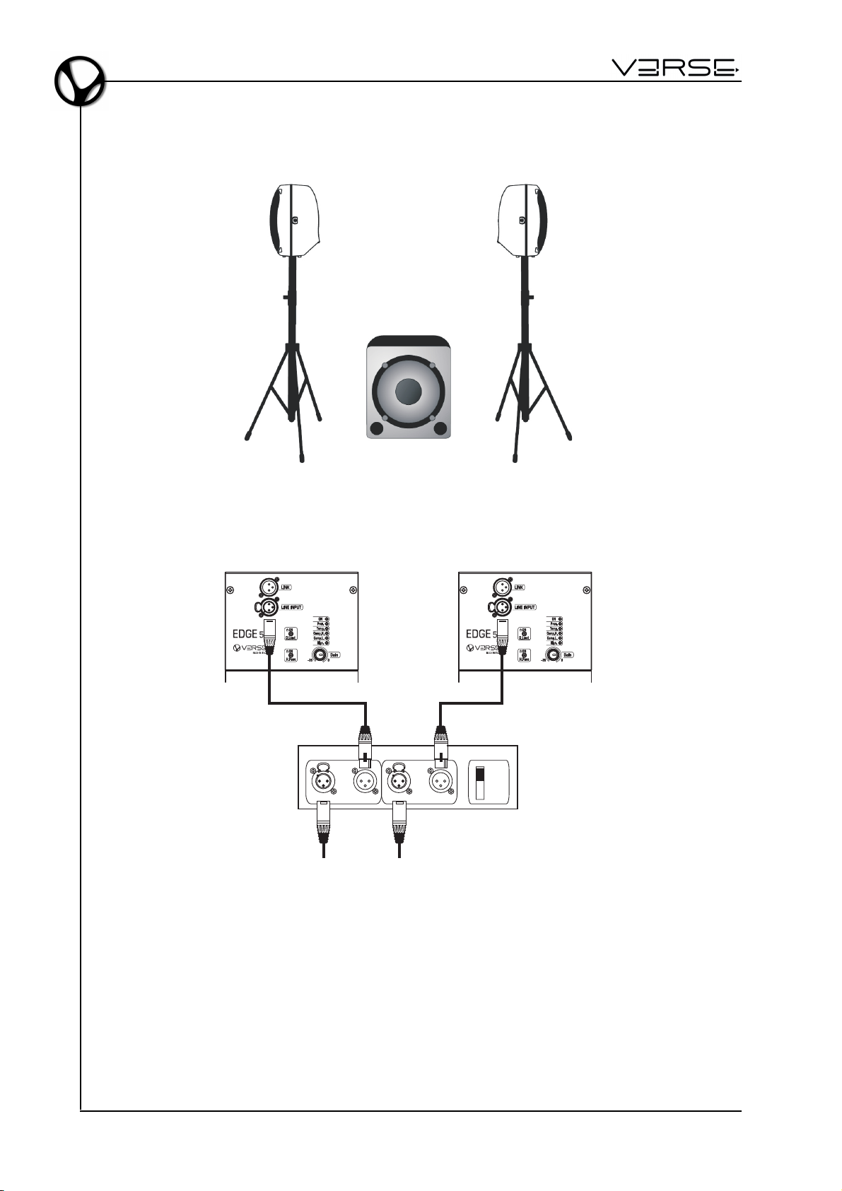
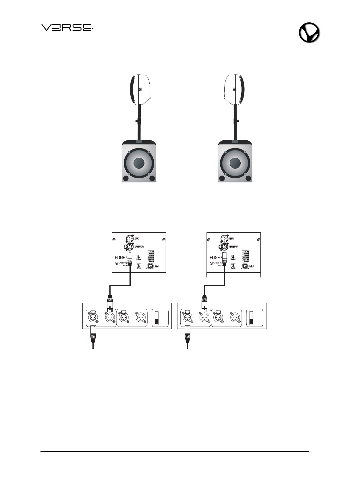
1 ACTIVE SUB + 2 EDGE 500 - STEREO
LEFT RIGHT
Left/Mono Right
Stereo
Input Link Input Link
Left
Source
Signal
Right
Source
Signal
ACTIVE SUB-WOOFER
Mono
EN - 6
Page 9
EDGE 500
- User Manual
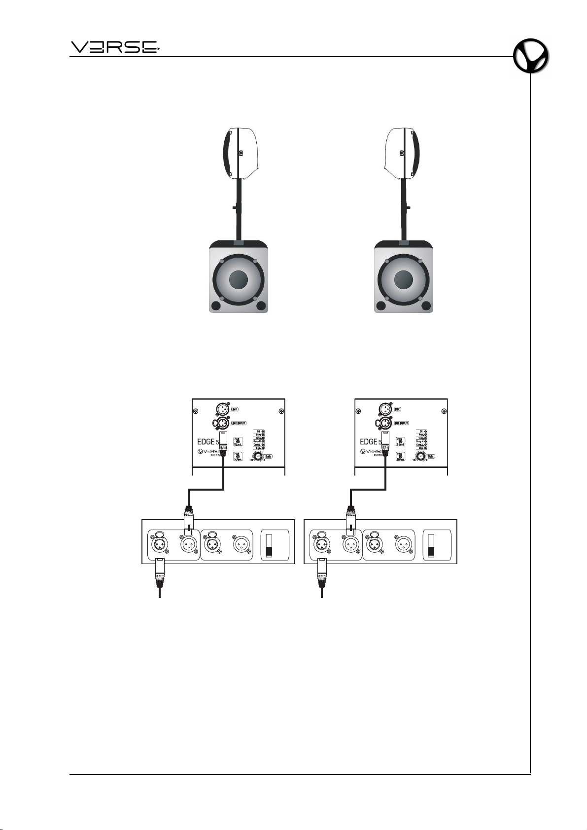
2 ACTIVE SUB + 2 EDGE 500 - STEREO
Left/Mono Right
Input Link Input Link
ACTIVE SUB-WOOFER
Left
Source
Signal
LEFT RIGHT
Left/Mono Right
Stereo
Mono
Input Link Input Link
ACTIVE SUB-WOOFER
Right
Source
Signal
Stereo
Mono
EN - 7
Page 10
User Manual - EDGE 500
COMPONENTS, CONFIGURATION AND PERFORMANCES
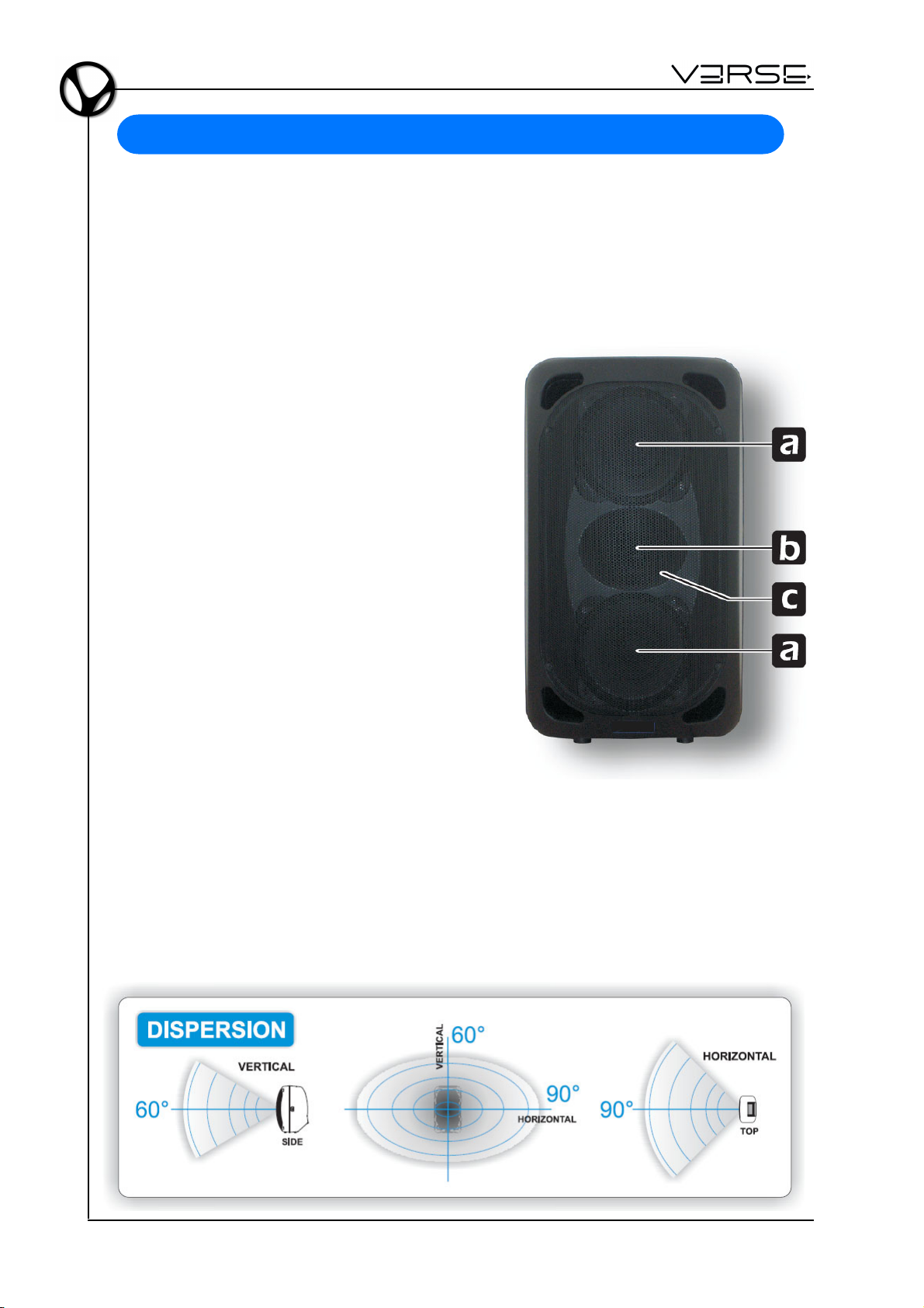
The diffusion section uses high efficiency custom devices, engineered in the special
configuration: 2 x 8” woofer + 1" compression driver.
The connection of these elements offers significant advantages for both the reliability
and the acoustic performance, especially in the reproduction of the vocal range.
Some examples:
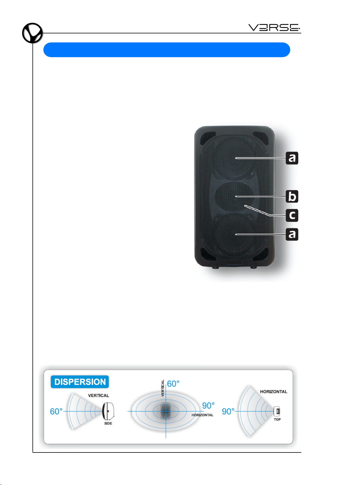
a. The double 8" woofer reduces the interacting
masses by 30% compared to the classic
configuration with a single 12" speaker. This
leads to a higher acceleration factor (faster
response to the transients), a wider
extension toward high frequencies and
therefore a better acoustic continuity among
high/low components of the system.
b. Using a 1" HF driver, made following the last
generation technologies and provided with
a polyestere diaphragm, causes a much
more efficient high frequencies (106 dB)
transduction, a wider frequency extension,
a better acceleration factor and a higher
reliability.
c. The HF driver is assembled on a elliptical
wave trumpet, designed for being free from
acoustic resonance and, at the same time,
for being characterised by a wide dispersion
angle, an excellent quality of the diffusion – even out of the axis – and a special
intelligibility of medium-high and high frequencies range. All these characteristic
provide an acoustic coherence that allows: - The audience: to enjoy the same
sound quality anywhere on the stand. - The performers: to maintain a constant
hearing perception, whenever the loudspeaker is placed vertically, for monitor use,
etc.
EN - 8
Page 11
EDGE 500
- User Manual
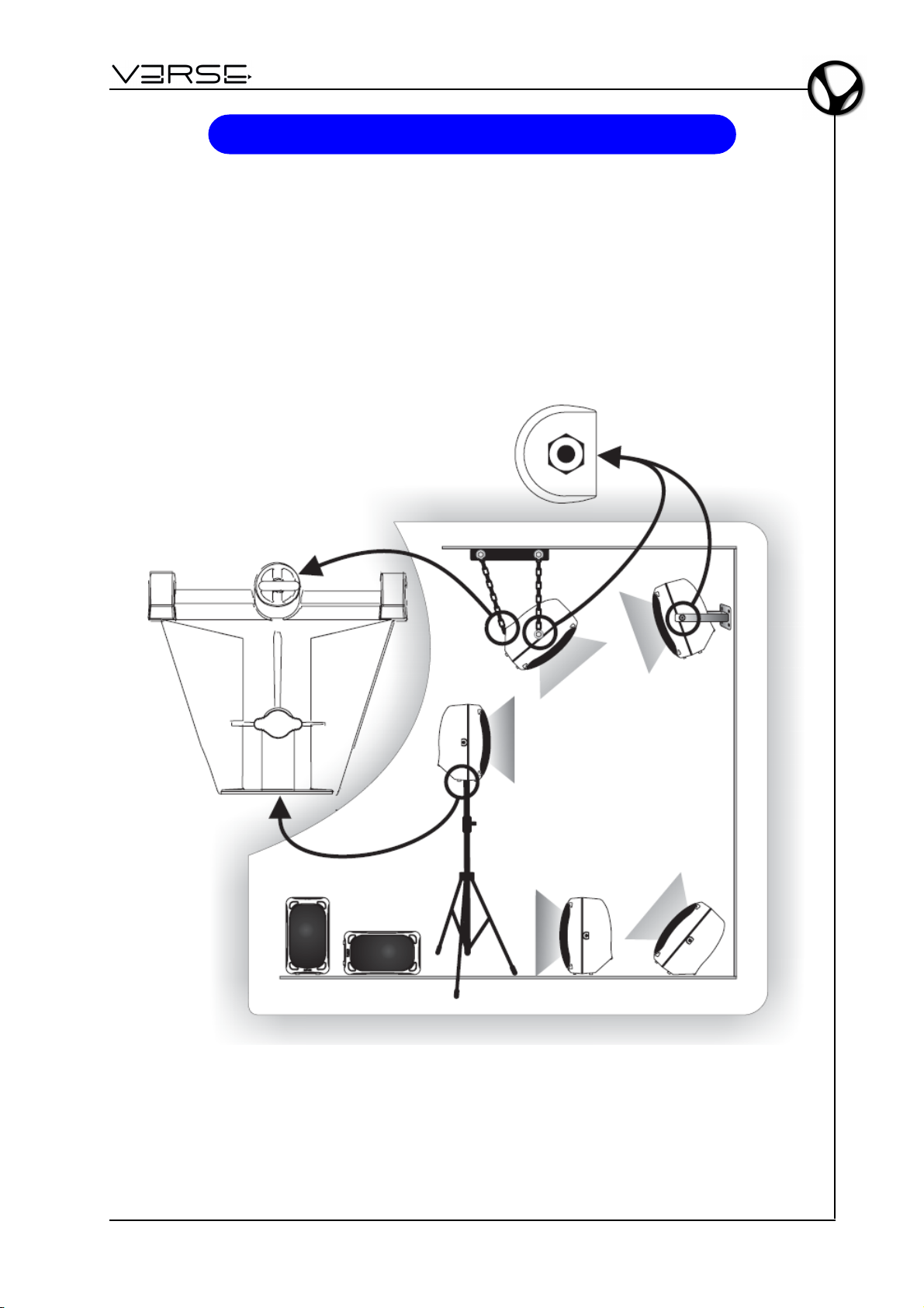
PLACEMENT
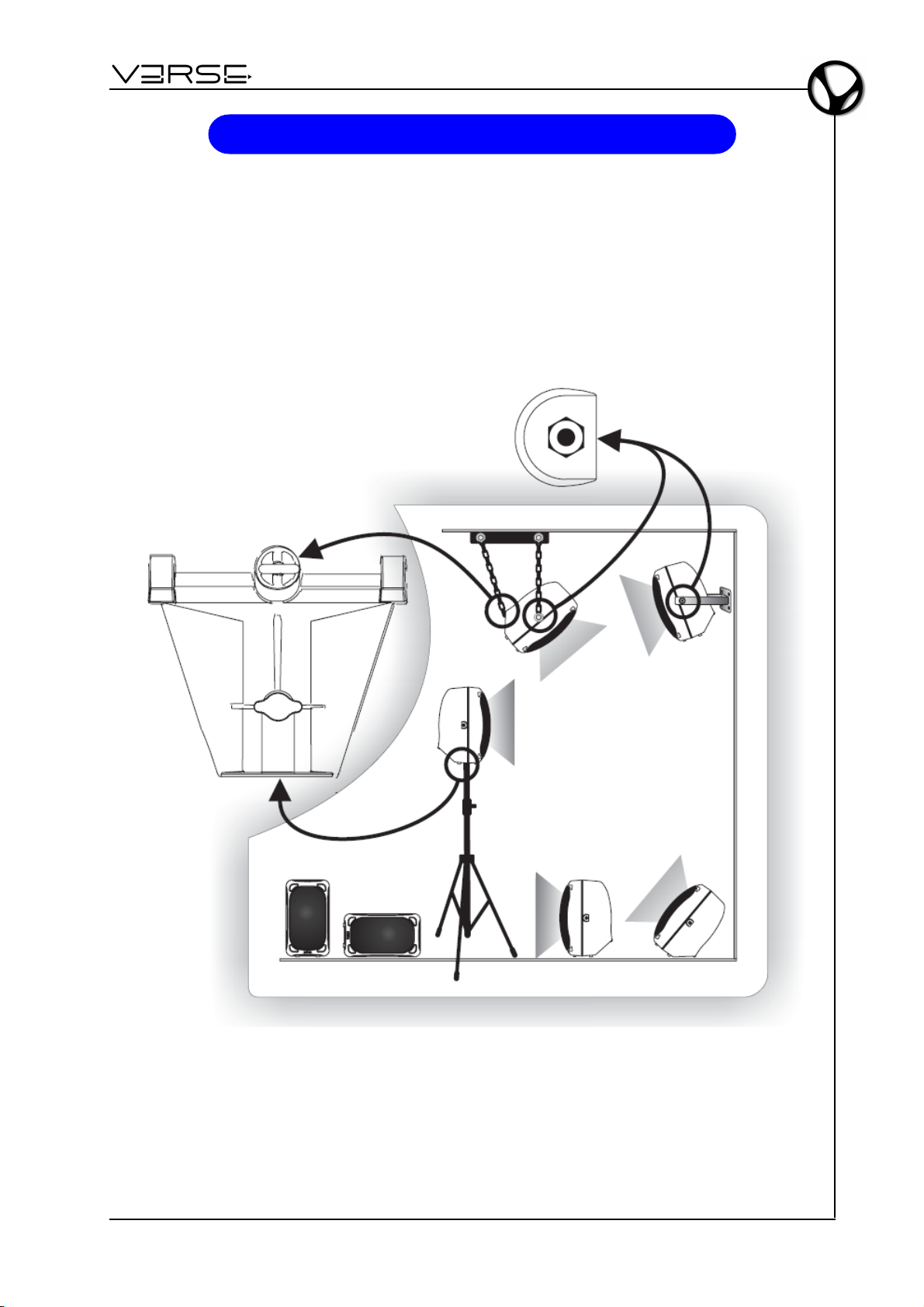
The design and mechanical fittings of the EDGE 500 cabinet make it easy to use and
install the system to suit specific requirements :
- on the floor: vertical, horizontal, or tilted in monitor-mode
- suspended: on a stand, wall-mounted or hung from technical structures.
The special component layout ensures that sound diffusion is always impeccable.
EN - 9
Page 12

User Manual - EDGE 500
POLE AND TRIPOD SAFETY RECOMMENDATION
This manual assumes that the owners and/or users of a VERSE System are
knowledgeable and experienced in the areas of Pole and Tripod use with loudspeaker
systems.
The suspension of large, heavy objects on Pole or Tripod in public places is subject to
numerous laws and regulations at the national/federal, state/provincial, and local levels,
that are not addressed in this manual.
However, the user must assume responsibility for making sure that use of any VERSE
system, its components and all the stands and poles and associated hardware in any
particular circumstance or venue conforms to all applicable laws and regulations in force
at the time.
WHEN USING STANDS OR POLES, BE SURE TO OBSERVE THE FOLLOWING
PRECAUTIONS.
CHECK THE STAND OR POLE SPECIFICATION TO BE CERTAIN THE DEVICE IS
DESIGNED TO SUPPORT THE WEIGHT OF THE SPEAKER. OBSERVE ALL SAFETY
PRECAUTIONS SPECIFIED BY THE MANUFACTURER. MAKE SURE THAT THE
SURFACE ON WHICH THE SYSTEM IS TO BE STACKED IS FLAT, STABLE AND
SOLID.
ROUTE CABLES SO THAT PERFORMERS, PRODUCTION CREW, AND AUDIENCE
WILL NOT TRIP AND TOPPLE THE SPEAKERS.
INSPECT THE STAND (OR POLE AND ASSOCIATED HARDWARE) BEFORE EACH
USE AND DO NOT USE EQUIPMENT WITH WORN, DAMAGED, OR MISSING PARTS.
DO NOT ATTEMPT TO PLACE MORE THAN ONE VERSE EDGE 500 LOUDSPEAKERS
ON A STAND OR POLE.
ALWAYS BE CAUTIOUS WHEN DEPLOYING THE SYSTEM OUTDOORS.
UNEXPECTED WINDS MAY TOPPLE A SYSTEM.
IT MAY BE NECESSARY TO PLACE ADDITIONAL WEIGHT (I.E.SANDBAGS) ON THE
BASE OF THE STAND TO IMPROVE STABILITY. AVOID ATTACHING BANNERS OR
SIMILAR ITEMS TO ANY PART OF A SPEAKER SYSTEM. SUCH ATTACHMENTS
COULD ACT AS A SAIL AND TOPPLE THE SYSTEM.
UNLESS YOU ARE CONFIDENT THAT YOU CAN HANDLE THE WEIGHT OF THE
SPEAKER, ASK ANOTHER PERSON TO HELP YOU GET IT ONTO THE TRIPOD
STAND OR POLE.
Whenever the VERSE speakers are going to be installed on a tripod, make sure that the
system stability is granted, in order to avoid toppling. The stability is determined by the
speaker placement height and the legs spread. Provided that the users are charged by
responsibility of a correct installation and of a thorough stability check, a reference for
the setup may be the following: using a tripod with a basis spread of at least 168cm, it is
possible to place the speaker up to 180cm high.
Whenever the VERSE speakers are placed on a pole, using a properly arranged
subwoofer speaker as support, the maximum stable height, granting stability and no
toppling of the system, depends on the subwoofer speaker dimensions.
EN - 10
Page 13

EDGE 500
Provided that the users are charged by responsibility of a correct installation and by
thorough stability check, a reference guideline is given by the following table:
- SUB 10 MKII: no
- SUB 15 MKII: max 90 cm
- SUB 18 MKII: max 135 cm
- SUB 215 MKII: max 130 cm
SUSPENSION SAFETY RECOMMENDATION
This manual assumes that the owners and/or users of a VERSE System are
knowledgeable and experienced in the areas of rigging and flying loudspeaker systems.
The suspension of large, heavy objects in public places is subject to numerous laws and
regulations at the national/federal, state/provincial, and local levels, that are not addressed
in this manual.
However, the user must assume responsibility for making sure that use of any VERSE
system and its components in any particular circumstance or venue conforms to all
applicable laws and regulations in force at the time.
- User Manual
MANY ISSUES OF CRUCIAL CONCERN, SUCH AS THE DETERMINATION OF
APPROPRIATENESS AND CONDITION OF VENUE RIGGING POINTS, CANNOT BE
ADDRESSED HERE. THEREFORE, THE USER MUST ASSUME ALL
RESPONSIBILITY FOR THE APPROPRIATE USE OF VERSE SYSTEMS IN ANY
PARTICULAR LOCATION OR CIRCUMSTANCE.
CONSEQUENTLY, USERS OF VERSE RIGGING SYSTEMS SHOULD BE PREPARED
TO TAKE ADDITIONAL SAFETY ASSURANCE MEASURES BEYOND THOSE
OUTLINED IN THIS MANUAL. IN ALL CASES, IT IS THE RESPONSIBILITY OF THE
USER TO MAKE CERTAIN THAT ANY VERSE LOUDSPEAKER SYSTEM IS
SUSPENDED IN ACCORDANCE WITH ALL APPLICABLE NATIONAL/FEDERAL, STATE/PROVINCIAL, AND LOCAL REGULATIONS.
As an extra precaution, careful inspection of the attachment points is advised before
flying, particularly in older venues or those hosting frequent events using large sound
and lighting systems.
In any case, VERSE systems are intended only for suspension from approved rigging
points, each known to have ample safe working loads margins for the system components
suspended below them.
EN - 11
Page 14

User Manual - EDGE 500
USAGE SUGGESTIONS
The acoustic characteristics of the room/environment in which a sound system is used
have sometimes very significant effects on the overall sound produced.
Thanks to its special technical features (such as the optimal width of its dispersion range),
with the EDGE 500 some of the most common problems can be reduced or prevented.
However, some factors should be borne in mind as they may help to optimise its
performance.
• Do not place speakers in the corners of a room or in recesses (e.g. niches), since
this causes an increase in the low frequencies, producing sounds which are redundant
or blurred.
• Do not place speakers against a wall, as this also causes an increase in the low
frequencies, although less pronounced than that produced in a corner or niche.
N.B.: on the other hand, this phenomenon may sometimes be used to advantage to
reinforce the low range, but it must be employed carefully and in a controlled way.
• Do not place speakers straight on a stage, a floating floor or any other support with
cavities, as this tends to trigger resonances that alter and interfere with the overall
sound.
N.B.: solid supports should always be used when possible, or a speaker stand.
• Remember that high frequencies have a high level of directivity and a much higher
absorption coefficient than low frequencies. Therefore, to guarantee that the signal
reaches the listener in an intelligible form, position speakers so that they are in a
direct line with the audience (clearly visible) about ½ metre / 1 metre above the
audience’s heads.
• In buildings with a lot of reverberation (places of worship, gymnasiums, etc.) first of
all keep the sound reflections down using materials which absorb sound (carpets,
curtains, special panels, etc.). If this is not possible or is not sufficient, do not simply
turn up the volume, because this will also increase the volume of the reflected sound,
and may make the situation even worse. The best solution is to use more speakers,
placed around the room and closer to the audience (e.g. front+back; front+sides;
front+sides+back).
EN - 12
Page 15
EDGE 500
@
LOW FREQUENCY SECTION
HIGH FREQUENCY SECTION
ACOUSTIC RESPONSE
CONSTRUCTION
AMPLIFIER SECTION
CONTROLS
DISPLAY LEDs
CONNECTORS
PHYSICAL FEATURES
- User Manual
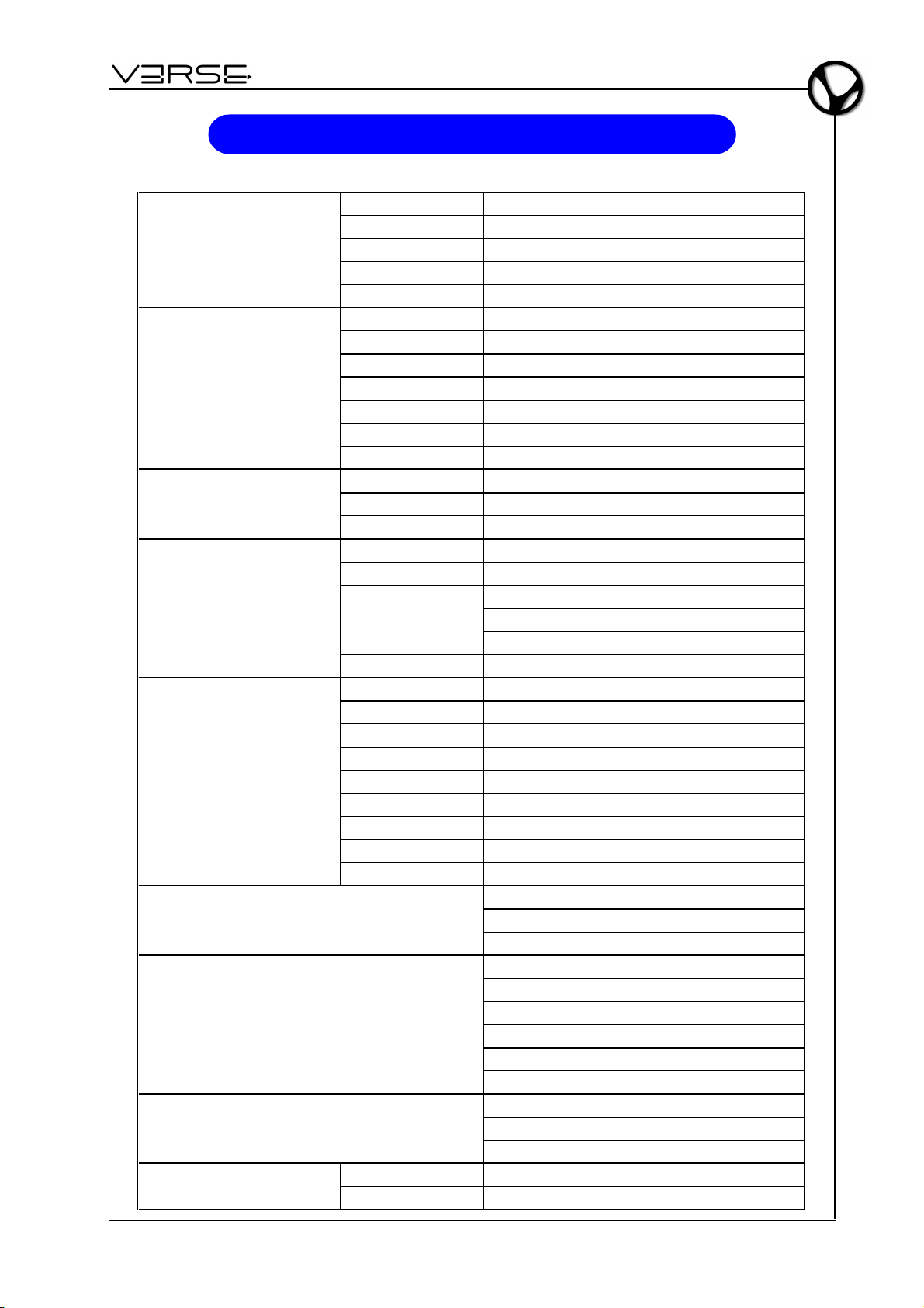
TECHNICAL SPECIFICATIONS
Number of Drivers 2
Woofer Diameter 8 inch / 209 mm
Voice Coil Diameter 2 inch / 50 mm
Winding Material Copper
Magnet Type Ferrite
Number of Drivers 1
Voice Coil Diameter 1.4 inch / 36 mm
Winding Material Aluminium
Throat Diameter 1 inch / 25 mm
Magnet Tipe Ferrite
Horn Design Elliptical Wave Guide
Horn Coverage 90° Horizontal - 60° Vertical
Maximum SPL Peak
Frequency Response 58 Hz ÷ 20 kHz
Crossover frequency 2400Hz
Material Polypropy lene – Composite molded high impact enclosure
Handles 2 on the sides – 1 on the top
Coupling
Protect ions Perforated and painted metal grid
Total Amplifier Power 415W - EIAJ (1kHz, 1% THD)
Max LF output power 350 W
Max HF output power 65 W
Distors ion <0.05% (THD, DIM, SMPTE)
Input sensitivity 0 dBu
Line Input impedance 30 kOhms (balanced) – 15kOhms (unbalanced)
Active protective circuitry Thermal, overload, short circuit, soft clip and voltage limiters
HF protection ptc
Subsonic filter Yes
Dimensions (W x H x D) 355 x 635 x 420 mm
Weight 16 Kg
1m 127 dB
1 hole on the bottom (for speaker stand fitting).
2 M8 screw mounting holes on the sides
1 hook on the rear (for speaker hanging)
Gain
Dynamic loudness
High pass filter
ON (Green Led)
Overload / short c ircuit protection (Red Led)
Thermal protect ion (Red Led)
Compressor high (Red Led)
Compressor low (Red Led)
Signal (Green Led)
Line Input: Female XLR
Link: Male XLR
AC Connector: 3 pin IEC 250 VAC with fuse
EN - 13
Page 16
User Manual - EDGE 500
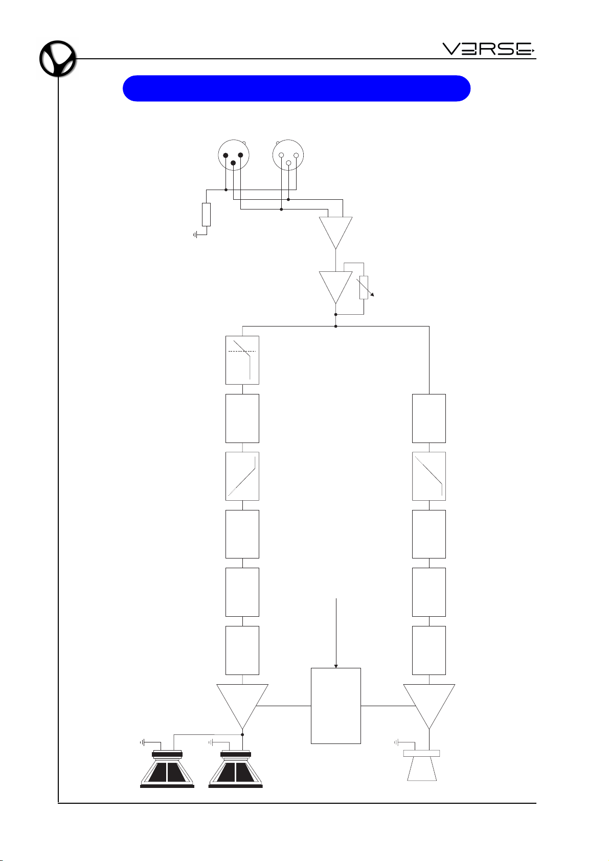
BLOCK DIAGRAM
LINE INPUT
LINK
LOAD
123
CHANNEL
DELAY
213
LOW CUT
CROSS-OVER
UNBAL
LINE LEVEL
CHANNEL
DELAY
CROSS-OVER
EQ
GAIN COMP/LIMITER
LO FREQ
AMP
WOOFER
EN - 14
VOLTAGE SENSE
LOW AC
SHORT CIRCUIT
PROTECTIONS
AND THERMAL
CONTINUOUS
VOLTAGE
EQ
GAIN COMP/LIMITER
HI FREQ
AMP
HF DRIVER
Page 17
Disposal of old Electrical & Electronic Equipment (Applìcable throughout the European Union
and other European countries with separate collection programs)
Dir. 2002/95/CE, 2002/96/CE e 2003/108/CE
This syrnbol, found on your product or on its packaging, indicates that this product should not be
treated as household waste when you wish to dispose of it. Instead, it should be handed overt to an
applicable collection point for the recycling of electrical and electronic equipment. By ensuring this
product is disposed of correctly, you will help prevent potential negative consequences to the
environment
and human health, which could otherwise be caused by inappropriate disposal of this product. The
recycling of materials will help to conserve natural resources. For more detailed information about the
recycling of this product, please contact your local city offi ce, waste disposal service or the retail store
where you purchased this product.
This product complies with the requirements of EMCD 2004/108/EC and LVD 2006/95/EC.
FCC RULES
NOTE: This equipment has been tested and found to comply with the limits for a Class B digital Device, persuant to Part 15 if the FCC
Rules. These limits are designed to provide reasonable protection against harmful interference in a residential installation. This
equipment generates, uses and can radiate radio frequency energy and, if not installed and used in accordance with the instruction,
may cause harmful interference to radio comunications. However, there is no guarantee that the interference will not occur in a
particular installation. If this equipment does cause harmful interference to radio or television reception, which can be determinated by
turning the equipment off and on, the user is encuraged to try to correct the interference by one or more of the following measures:
- Reorient or relocate the receiving antenna.
- Increase the separation between the equipment and receiver.
- Connect the equipment into an outlet on a circuit different from that to which the receiver is connected.
- Consult the dealer or an experienced Radio/Tv technician for help.
The user is cautioned that any changes or modification not expressly approved by the party responsable for compliance could void the
user’s authority opearate the equipment.
INFORMATIONS FCC
NOTE : Cet instrument a été controlé et il est garanti pour etre en conformité avec les spécifications techniques établies pour les
dispositifs numériques de la « Classe B » selon les normes de protection contre les interférences avec d’autres dispositifs électroniques
environnants. Cet appareil produit et utilise des fréquences radio. S’il n’est pas installé et utilisé selon les instructions contenues dans le
mode d’emploi, il peut générer des interférences. L’observation des normes FCC ne garanti pas qu’il y aura aucune interférence. Si cet
appareil est la cause d’ interférences avec une réception Radio ou TV, il est possible
de le vérifier en éteignant puis en allumant l’instrument : Vous pouvez alors résoudre le problème en suivant les procédures suivantes :
- déplacer ou orienter l’antenne de l’appareil avec lequel se manifeste l’interférence.
- déplacer cet instrument ou l’appareil avec lequel se produit l’interférence
- connecter cet instrument à une prise de courant différente afin de mettre les deux appareils sur deux circuits différents.
- consulter le revendeur ou un technicien radio/tv pour d’autres renseignements.
D’éventuelles modifications non approuvées par le constructeur peuvent annuler votre garantie de l’appareil.
Page 18
Page 19

EDGE 500
- Manuale Utente
INDICE
Note importanti ............................................................................................................ 1
Presentazione ............................................................................................................. 2
Controlli e connessioni ................................................................................................ 3
Esempi di collegamento .............................................................................................. 5
Componenti, configurazione e prestazioni .................................................................. 8
Posizionamento ........................................................................................................... 9
Suggerimenti d’uso.................................................................................................... 12
Specifiche tecniche.................................................................................................... 13
Schema a blocchi ...................................................................................................... 14
NOTE IMPORTANTI
CURA DEL PRODOTTO
• Non applicate eccessiva forza alle strutture ed ai comandi (manopole, interruttori).
• Evitate forti sollecitazioni della cassa sia nel corso del trasporto che durante il suo
utilizzo.
• Evitate di posizionare l’apparecchio in prossimità di fonti di calore, in luoghi umidi o
polverosi o nelle vicinanze di forti campi magnetici.
• Non collocare, quando possibile, la cassa in prossimità di unità che producano forti
interferenze come apparecchi radio – TV, monitor, ecc...
• Non introdurre per nessuna ragione oggetti estranei o liquidi di qualsiasi genere
all’interno dell’apparecchio.
• Per la pulizia usate solo un pennello morbido od aria compressa, non usate mai
detergenti, solventi od alcool.
• Quando scollegate i cavi dalle prese abbiate cura di afferrarli per il connettore e non
per il cavo stesso; avvolgendoli, inoltre, evitate nodi e torsioni.
• Evitate di esporre la cassa all’irradiazione solare diretta ed alla pioggia.
COLLEGAMENTO ALLA RETE
• Per evitare il rischio di shock elettrico non effettuare i collegamenti con le mani bagnate.
• Accertatevi che la tensione di rete corrisponda a quella indicata sul pannello dei
comandi.
• Collegate la cassa ad una presa di rete provvista di contatto a terra.
COLLEGAMENTO AD UN MIXER
• Utilizzate sempre cavi schermati di buona qualità.
• Prima di effettuare i collegamenti accertatevi che tutte le casse che state per colle-
gare siano spente. Eviterete rumorosi se non pericolosi picchi di segnale.
IN CASO DI AVARIA
• In caso di avaria rivolgetevi esclusivamente ad un centro di assistenza autorizzato
VERSE.
IT - 1
Page 20
Manuale Utente - EDGE 500
PRESENTAZIONE
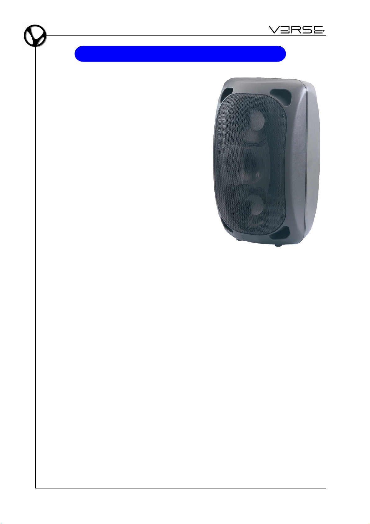
EDGE 500 è un diffusore attivo che unisce tecnologia, esperienza e gusto in un sapiente mix di qualità sonora, potenza e semplicità d’uso. E’ equipaggiato con 2 woofer custom da 8" + driver a compressione da 1", 2 processori di segnale indipendenti per alte e basse frequenze.
L’altoparlante è assistito da una catena di
processamento digitale del segnale, da una bi-amplificazione da 350W+65W e da un’accurata
ingegnerizzazione acustica che ne perfezionano i
risultati in termini di intelligibilità della riproduzione
acustica, di ampiezza e di costanza della diffusione, di potenza e di precisione dell’amplificazione.
Il cabinet, realizzato in polypropilene con finitura
antigraffio, è caratterizzato da un design ricercato
ed è dotato di accorgimenti che facilitano l’uso e
l’installazione del diffusore in diverse posizioni, sia
a terra sia in sospensione.
EDGE 500 si presenta come una soluzione ideale
per tutte le piccole e medie sonorizzazioni nelle
quali sia importante ottenere la massima copertura sonora con il minor numero di diffusori possibile.
TECNOLOGIA
AMPLIFICATORI
La nuova tecnologia digitale ha cambiato il modo in cui si progetta l’amplificazione audio
professionale. In nessun altro modo si può rispondere alla richiesta di grande potenza e
affidabilità di lungo termine.
Grazie alla notevole riduzione del calore prodotto ed alla altrettanto considerevole riduzione del peso, gli amplificatori digitali di cui sono equipaggiati i diffusori VERSE offrono
grande efficienza, grande potenza e ridotta dissipazione di calore. Gli stadi di uscita di
questi amplificatori, lavorano tipicamente al 95% di efficienza, dissipando appena il 5%
di energia sotto forma di calore. Inoltre l’efficienza non è legata al livello di uscita, e
considerando che il programma musicale ha mediamente una densità di potenza pari al
40% del massimo livello, gli amplificatori convenzionali generano dieci volte più calore,
a parità di volume di suono.
Per garantire grande affidabilità e durata nel tempo, sono state adottate protezioni contro il corto-circuito, protezione termica con controllo della velocità di rotazione della ventola
di raffreddamento che non fa mai salire la temperatura oltre i 60 gradi, ulteriore protezione che disattiva l’amplificatore qualora superasse valori intollerabili di temperatura, protezione verso componenti continue ed ancora protezione verso componenti ultrasoniche
sia in ingresso che in uscita. L’ I.T.P. (Intelligent Termal Protect) è garanzia di un perfetto
e duraturo funzionamento del diffusore.
IT - 2
Page 21
EDGE 500
PROCESSORI
I processori comprendono cross-over e filtri passa-banda, compressori/limitatori di livello, delay per l’allineamento in fase dei componenti. Il funzionamento dei processori è
automatico ed è concepito per assicurare le migliori condizioni di riproduzione e di sicurezza.
In dettaglio ognuna delle due vie ha il proprio limitatore che interviene sulla sezione di
equalizzazione e non come usualmente accade semplicemente sul livello. Questo consente, anche in caso di intervento del limiter, di alterare il meno possibile la risposta del
diffusore, poichè viene attenuata solo la regione di frequenze più critiche.
- Manuale Utente
CONTROLLI E CONNESSIONI
1
2
3
4
5
6
7
8
IT - 3
Page 22

Manuale Utente - EDGE 500
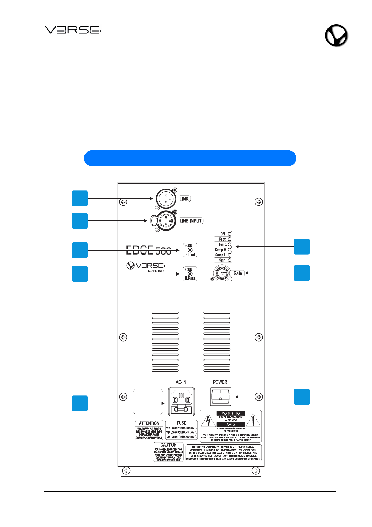
1. Link: invia in uscita lo stesso segnale proveniente dal connettore LINE INPUT. Questo permette di collegare in cascata più dispositivi alla stessa sorgente sonora.
2. Line Input: connettore XLR bilanciato per l'ingresso del segnale da amplificare.
3. D.Loud.: attiva la funzione di equalizzazione dinamica del sistema, allo scopo di
compensare la minore sensibilità dell'orecchio umano, sia alle frequenze più basse
che a quelle più alte, quando il diffusore è utilizzato a basso volume di emissione
sonora. L'equalizzazione è dinamica, consentendo così di regolarne con continuità
l'entità, in funzione del livello di segnale, fino a scomparire ad altissimi livelli di emissione.
4. H.Pass: attiva un filtro passa-alto, posizionato in maniera ottimale per usare il diffusore in abbinamento ad un subwoofer. Con il filtro non inserito, il diffusore si comporta da Full-Range, mentre con il filtro inserito si ha la funzionalità "satellite" da abbinare ad un subwoofer.
5. AC-IN: presa per il cavo di alimentazione. La presa è dotata di un fusibile, collocato
in un alloggiamento protetto. In caso di sostituzione, è importantissimo attenersi alle
seguenti indicazioni:
- spegnere l’apparato;
- rimuovere il cavo di alimentazione;
- accedere al vano porta-fusibile aprendo l’apposito sportelletto con un cacciavite;
- effettuare la sostituzione con un fusibile dalle caratteristiche identiche, ovvero T2A
L 250V nella versione 230 VAC o T4A L 250V nelle versioni 120 VAC e 100 VAC;
- richiudere lo sportelletto.
6. Indicatori LED:
- ON: indica che lo speaker è acceso.
- Prot.: indica che l'amplificatore interno è entrato in protezione a causa di un guasto
dell'amplificatore stesso o degli altoparlanti collegati (rivolgersi all'assistenza tecnica).
- Temp.: indica che l'amplificatore interno è entrato in protezione a causa del
raggiungimento di un calore eccessivo. In questa condizione, l'amplificatore eroga
metà della potenza disponibile. Ridurre il segnale in ingresso per consentire il ripristino delle normali condizioni di lavoro.
- Comp. H.: indica che il compressore della sezione "High" è in funzione. Se il se-
gnale supera la soglia di sicurezza il compressore garantisce una riproduzione
fedele, senza distorsione, attenuando solamente le frequenze di segnale
appropriate. Il sistema opera in completa sicurezza. Se il LED è costantemente
acceso c'è un eccesso di segnale, si consiglia di ridurre il livello del segnale in
ingresso.
- Comp. L.: indica che il compressore della sezione "Low" è in funzione. Se il segna-
le supera la soglia di sicurezza il compressore garantisce una riproduzione fedele,
senza distorsione, attenuando solamente le frequenze di segnale appropriate. Il
sistema opera in completa sicurezza. Se il LED è costantemente acceso c'è un
eccesso di segnale, si consiglia di ridurre il livello del segnale in ingresso.
- Sign.: indica che il segnale è presente.
7. Gain: modifica il guadagno del segnale in ingresso tra -35dB e 0dB.
8. POWER: interruttore di accensione/spegnimento.
IT - 4
Page 23
EDGE 500
G
A
I
N
L
I
N
E
I
M
C
G
A
I
N
S
E
N
S
I
T
I
V
I
T
Y
L
I
N
E
G
A
I
N
L
I
N
E
I
M
C
G
A
I
N
S
E
N
S
I
T
I
V
I
T
Y
L
I
N
E
-10dB
+10-30
-50dB
G
A
I
N
L
I
N
E
I
M
C
G
A
I
N
S
E
N
S
I
T
I
V
I
T
Y
L
I
N
E
-10dB
+10-30
-50dB-10dB
+10-30
-50dB
G
A
I
N
L
I
N
E
I
M
C
G
A
I
N
S
E
N
S
I
T
I
V
I
T
Y
L
I
N
E
G
A
I
N
L
I
N
E
I
M
C
G
A
I
N
S
E
N
S
I
T
I
V
I
T
Y
L
I
N
E
-10dB
+10-30
-50dB
G
A
I
N
L
I
N
E
I
M
C
G
A
I
N
S
E
N
S
I
T
I
V
I
T
Y
L
I
N
E
-10dB
+10-30
-50dB-10dB
+10-30
-50dB
G
A
I
N
L
I
N
E
I
M
C
G
A
I
N
S
E
N
S
I
T
I
V
I
T
Y
L
I
N
E
G
A
I
N
L
I
N
E
I
M
C
G
A
I
N
S
E
N
S
I
T
I
V
I
T
Y
L
I
N
E
-10dB
+10-30
-50dB
G
A
I
N
L
I
N
E
I
M
C
G
A
I
N
S
E
N
S
I
T
I
V
I
T
Y
L
I
N
E
-10dB
+10-30
-50dB-10dB
+10-30
-50dB
G
A
I
N
L
I
N
E
I
M
C
G
A
I
N
S
E
N
S
I
T
I
V
I
T
Y
L
I
N
E
G
A
I
N
L
I
N
E
I
M
C
G
A
I
N
S
E
N
S
I
T
I
V
I
T
Y
L
I
N
E
-10dB
+10-30
-50dB
G
A
I
N
L
I
N
E
I
M
C
G
A
I
N
S
E
N
S
I
T
I
V
I
T
Y
L
I
N
E
-10dB
+10-30
-50dB-10dB
+10-30
-50dB
G
A
I
N
L
I
N
E
I
M
C
G
A
I
N
S
E
N
S
I
T
I
V
I
T
Y
L
I
N
E
G
A
I
N
L
I
N
E
I
M
C
G
A
I
N
S
E
N
S
I
T
I
V
I
T
Y
L
I
N
E
-10dB
+10-30
-50dB
G
A
I
N
L
I
N
E
I
M
C
G
A
I
N
S
E
N
S
I
T
I
V
I
T
Y
L
I
N
E
-10dB
+10-30
-50dB-10dB
+10-30
-50dB
G
A
I
N
L
I
N
E
I
M
C
G
A
I
N
S
E
N
S
I
T
I
V
I
T
Y
L
I
N
E
G
A
I
N
L
I
N
E
I
M
C
G
A
I
N
S
E
N
S
I
T
I
V
I
T
Y
L
I
N
E
-10dB
+10-30
-50dB
G
A
I
N
L
I
N
E
I
M
C
G
A
I
N
S
E
N
S
I
T
I
V
I
T
Y
L
I
N
E
-10dB
+10-30
-50dB-10dB
+10-30
-50dB
G
A
I
N
L
I
N
E
I
M
C
G
A
I
N
S
E
N
S
I
T
I
V
I
T
Y
L
I
N
E
G
A
I
N
L
I
N
E
I
M
C
G
A
I
N
S
E
N
S
I
T
I
V
I
T
Y
L
I
N
E
-10dB
+10-30
-50dB
G
A
I
N
L
I
N
E
I
M
C
G
A
I
N
S
E
N
S
I
T
I
V
I
T
Y
L
I
N
E
-10dB
+10-30
-50dB-10dB
+10-30
-50dB
G
A
I
N
L
I
N
E
I
M
C
G
A
I
N
S
E
N
S
I
T
I
V
I
T
Y
L
I
N
E
G
A
I
N
L
I
N
E
I
M
C
G
A
I
N
S
E
N
S
I
T
I
V
I
T
Y
L
I
N
E
-10dB
+10-30
-50dB
G
A
I
N
L
I
N
E
I
M
C
G
A
I
N
S
E
N
S
I
T
I
V
I
T
Y
L
I
N
E
-10dB
+10-30
-50dB-10dB
+10-30
-50dB
- Manuale Utente
ESEMPI DI COLLEGAMENTO
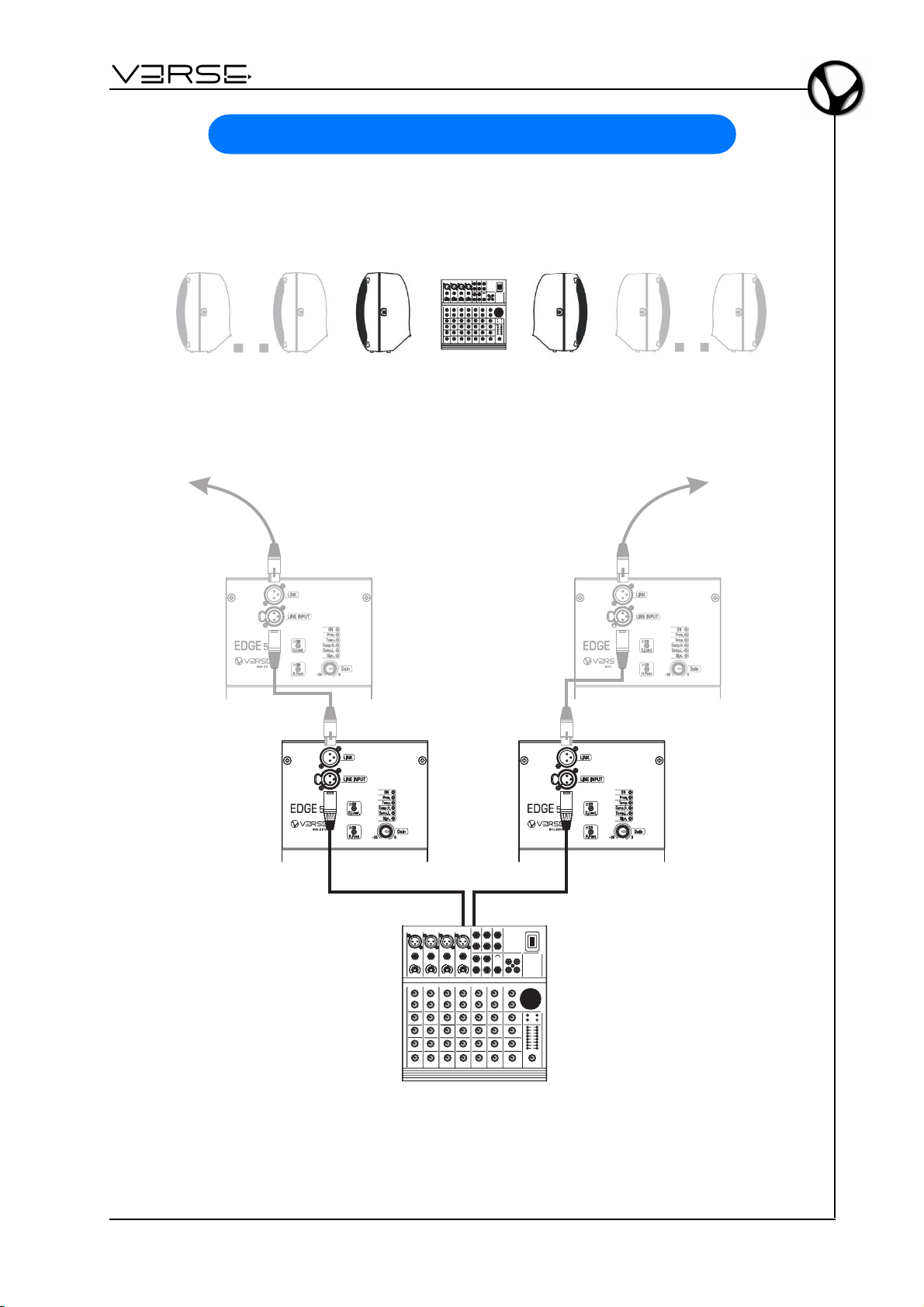
MIXER + 2 (o più) EDGE 500 - STEREO
LEFT RIGHT
Left Out Right Out
MIXER
IT - 5
Page 24
Manuale Utente - EDGE 500
1 ACTIVE SUB + 2 EDGE 500 - STEREO
LEFT RIGHT
Left/Mono Right
Stereo
Input Link Input Link
Left
Source
Signal
Right
Source
Signal
ACTIVE SUB-WOOFER
Mono
IT - 6
Page 25
EDGE 500
- Manuale Utente
2 ACTIVE SUB + 2 EDGE 500 - STEREO
Left/Mono Right
Input Link Input Link
ACTIVE SUB-WOOFER
Left
Source
Signal
LEFT RIGHT
Left/Mono Right
Stereo
Mono
Input Link Input Link
ACTIVE SUB-WOOFER
Right
Source
Signal
Stereo
Mono
IT - 7
Page 26
Manuale Utente - EDGE 500
COMPONENTI, CONFIGURAZIONE E PRESTRAZIONI
La sezione di diffusione utilizza dispositivi custom ad altissima efficienza, ingegnerizzati
nella speciale configurazione 2 woofer da 8” + driver a compressione da 1".
La combinazione di questi elementi offre significativi vantaggi nell’affidabilità e nelle
prestazioni sonore, specialmente nella riproduzione della gamma vocale.
Alcuni esempi:
a. L’adozione del doppio woofer custom da 8”
riduce le masse in gioco di circa il 30% rispetto alla canonica configurazione con singolo altoparlante da 12". Ne derivano un incremento del fattore d'accelerazione (risposta ai transienti più rapida), una maggiore
estensione verso le alte frequenze e quindi
una miglior continuità acustica tra i componenti dedicati alle vie Hi e Low del sistema.
b. L’impiego di un HF driver da 1” realizzato
con tecnologie di ultima generazione e dotato di diaframma in polyestere determina
un sensibile incremento di efficienza nella
trasduzione delle frequenze alte (106 dB),
una maggior estensione in frequenza, un
miglior fattore d'accelerazione e una superiore affidabilità.
c. La tromba a guida d’onda ellittica sul quale
l’HF driver è montato si avvale di un design
che la rende esente da risonanze acustiche, conferendo, al tempo stesso, un ampio
angolo di dispersione, una eccellente qualità della diffusione anche fuori-asse ed
una particolare intelligibilità della gamma di frequenze medio-alta e alta. Agli effetti
pratici, ciò si traduce in una notevole coerenza acustica che permette:
- al pubblico: di godere della medesima qualità in qualsiasi punto di una platea;
- ai performers: di mantenere una costante percezione d’ascolto anche nei diversi
posizionamenti fisici del diffusore: in verticale, inclinato uso-monitor, etc.
IT - 8
Page 27
EDGE 500
- Manuale Utente
POSIZIONAMENTO
Il design e le dotazioni meccaniche del cabinet di EDGE 500 rendono agevole l’utilizzo
e l’installazione del diffusore in funzione delle necessità:
- a terra: in verticale, in orizzontale o inclinato uso-monitor
- in sospensione: su stativo, fissato a parete o appeso a strutture attrezzate.
La speciale configurazione dei componenti assicura sempre una corretta diffusione sonora.
IT - 9
Page 28

Manuale Utente - EDGE 500
RACCOMANDAZIONI PER LA SICUREZZA IN CASO DI UTILIZZO DI PALO O
STATIVO
In questo manuale si assume che l’utente od il proprietario del sistema VERSE abbia
conoscenza ed esperienza nell’installazione di sistemi di casse acustiche con l'utilizzo
di stativi e treppiedi da terra, così come con pali per la sospensione sulle casse Subwoofer.
L’installazione su pali o stativi di oggetti di grandi dimensioni e di peso notevole in spazi
pubblici deve sottostare a numerose leggi e regolamentazioni ai differenti livelli locali e
nazionali che non sono oggetto di questo manuale.
In ogni caso l’utente deve assumersi ogni responsabilità relativamente all’uso in sicurezza dei sistemi VERSE ed all'utilizzo di apparecchiature idonee alla loro sospensione
in ogni particolare circostanza e luogo, in conformità alle leggi e regolamenti vigenti.
QUANDO SI USANO STATIVI O PALI, ASSICURATEVI DI OSSERVARE LE PRECAUZIONI DESCRITTE NEL SEGUITO.
VERIFICARE ATTENTAMENTE CHE LE SPECIFICHE DELLO STATIVO O DEL PALO
PER ESSERE SICURI CHE L'APPARECCHIATURA È PROGETTATA PER SOSTENERE IL PESO DELLA CASSA CHE SI VUOLE SOSPENDERE. OSSERVARE TUTTE LE
PRECAUZIONI DI SICUREZZA SPECIFICATE DAL FABBRICANTE DELLO STATIVO
O DEL PALO. ACCERTARSI CHE LA SUPERFICIE SULLA QUALE SARÀ DISPOSTO
IL SISTEMA SIA PIANA, STABILE E NON SDRUCCIOLEVOLE.
DISPORRE I CAVI DI RETE E DI SEGNALE IN MODO TALE CHE ESECUTORI, PERSONALE DI SERVIZIO E PUBBLICO NON INCIAMPINO E FACCIANO TRABALLARE
LA CASSA SOSPESA SULLO STATIVO O PALO.
ISPEZIONARE LO STATIVO OD IL PALO PRIMA DI OGNI UTILIZZO E NON UTILIZZARE MAI ATTREZZATURE CON PARTI USURATE, DANNEGGIATE O MANCANTI.
NON MONTARE MAI PIÙ DI UNA CASSA EDGE 500 SU UNO STATIVO O PALO.
QUANDO SI UTILIZZANO SISTEMI DI CASSE IN ISTALLAZIONI ALL'APERTO È
MOLTO IMPORTANTE FARE ATTENZIONE A VENTI INASPETTATI CHE POSSONO
FARE TRABALLARE E ROVESCIARE IL SISTEMA.
PUÒ ESSERE NECESSARIO PREDISPORRE DEI PESI SUPPLEMENTARI (AD ESEMPIO SACCHETTI DI SABBIA) SULLA BASE DELLO STAND PER MIGLIORARNE LA
STABILITÀ. EVITARE DI LEGARE BANDIERE O ARTICOLI SIMILI A QUALSIASI PARTE DI UN SISTEMA DI CASSE, COSÌ DA EVITARE CHE SI COMPORTI COME UNA
VELA E FACCIA ROVESCIARE IL SISTEMA. SE NON SI È SICURI DI POTER REGGERE DA SOLI IL PESO DEL DIFFUSORE, È OPPORTUNO CHIEDERE AD UN'ALTRA PERSONA UN AIUTO PER SOLLEVARE LA CASSA FIN SULLA CIMA DEL PALO
O DELLO STATIVO.
Qualora i diffusori della serie VERSE vengano installati utilizzando uno stativo occorre
accertarsi che sia garantita la stabilità del sistema, determinata sia dall'altezza alla quale si pone il diffusore, sia dalla larghezza con cui vengono aperti i piedi dello stativo
stesso, al fine di evitarne il ribaltamento. Pur rimanendo a carico dell'utente la responsabilità di una corretta installazione e della verifica di stabilità, vale la seguente indicazione
di riferimento: se si dispone di uno stativo la cui apertura di base sia non inferiore a 168
cm, è possibile montare il diffusore fino ad una altezza di 180 cm.
IT - 10
Page 29

EDGE 500
Qualora i diffusori della serie VERSE siano montati su palo, utilizzando come base una
cassa Subwoofer predisposta, l’altezza che garantisce la stabilità ed il non ribaltamento
del sistema dipende dalle dimensioni della cassa subwoofer. Pur rimanendo a carico
dell’utente la responsabilità di una corretta installazione e della verifica di stabilità, valgono le indicazioni riportate nella seguente tabella:
- SUB 10 MKII: no
- SUB 15 MKII: max 90 cm
- SUB 18 MKII: max 135 cm
- SUB 215 MKII: max 130 cm
RACCOMANDAZIONI PER LA SICUREZZA DELLE INSTALLAZIONI SOSPESE
In questo manuale si assume che l’utente od il proprietario del sistema VERSE abbia
conoscenza ed esperienza nell’installazione sospesa di sistemi di casse acustiche.
L’installazione sospesa di oggetti di grandi dimensioni e di peso notevole in spazi pubblici deve sottostare a numerose leggi e regolamentazioni ai differenti livelli locali e
nazionali che non sono oggetto di questo manuale.
In ogni caso l’utente deve assumersi ogni responsabilità relativamente all’uso dei sistemi VERSE in ogni particolare circostanza e luogo, in conformità alle leggi e regolamenti
vigenti per quelle particolari condizioni di utilizzo, circostanza, luogo e tempo.
- Manuale Utente
GLI ASPETTI CRUCIALI, COME LA DETERMINAZIONE DELL’ APPROPRIATEZZA E
LA CONDIZIONE DEI PUNTI DI ANCORAGGIO DELLA SEDE DI INSTALLAZIONE
SOSPESA, NON POSSONO ESSERE PRESI QUI IN CONSIDERAZIONE. PERCIÒ,
L'UTENTE DEVE ASSUMERSI TUTTA LA RESPONSABILITÀ PER L'USO APPROPRIATO DEI SISTEMI VERSE IN CIASCUNA PARTICOLARE UBICAZIONE O CIRCOSTANZA. DI CONSEGUENZA, L’UTENTE DEI SISTEMA VERSE DEVE PREDISPORRE MISURE DI SICUREZZA SUPPLEMENTARE OLTRE QUELLE DELINEATE
IN QUESTO MANUALE IN FUNZIONE DELLA PARTICOLARITA’ DELL’INSTALLAZIONE SOSPESA.
IN TUTTI I CASI, È’ RESPONSABILITÀ DELL'UTENTE ACCERTARSI CHE IL SISTEMA DI ALTOPARLANTI VERSE È SOSPESO IN CONCORDANZA CON TUTTE LE
LEGGI E REGOLAMENTI NAZIONALI E LOCALI VALIDI NEL LUOGO DELL’INSTALLAZIONE.
Come una precauzione addizionale, è opportuna una ispezione accurata dei punti di
aggancio prima di sospendere le casse dei sistemi VERSE, particolarmente qualora
l’installazione avvenga in locali o sedi di non recente costruzione o in quelli dove vi sono
eventi frequenti e dove vengono usati grandi sistemi per il suono e per le luci.
In ogni caso, i sistemi VERSE vanno utilizzati in installazioni sospese solamente su
attrezzature approvate, delle quali siano note le caratteristiche relative ai carichi sospesi sopportati e che consentano ampi margini per il peso dei componenti dei sistemi
VERSE sospesi sotto tali attrezzature.
IT - 11
Page 30

Manuale Utente - EDGE 500
SUGGERIMENTI D’USO
Le caratteristiche acustiche dell’ambiente nel quale si effettua una diffusione incidono
sul risultato sonoro complessivo, talvolta in modo molto significativo.
Gli speaker VERSE, grazie alle loro peculiarità tecniche (ad esempio: l’ampio angolo di
dispersione), consentono di contenere o prevenire alcuni degli inconvenienti tipici. Qualche accorgimento d’installazione, tuttavia, può contribuire a ottimizzarne le prestazioni.
• Evitate di collocare i diffusori negli angoli di una stanza o in cavità (es. nicchie),
poiché ciò determina un incremento delle basse frequenze, causando suoni ridondanti e poco distinti.
• Evitate di collocare i diffusori contro un muro, poiché ciò determina un incremento
delle basse frequenze, anche se in modo più contenuto rispetto alla collocazione in
un angolo o in una nicchia.
NOTA: per contro, questo fenomeno può talora essere vantaggiosamente sfruttato
proprio per rinforzare la gamma bassa, ma è opportuno che ciò sia praticato con
consapevolezza e in modo controllato.
• Evitate di far poggiare i diffusori direttamente su un palco, su un pavimento galleggiante o su un altro supporto con cavità, poiché ciò tende ad indurre risonanze che
alterano e disturbano il risultato sonoro complessivo.
NOTA: usate di preferenza un appoggio solido (pieno) o uno stativo per casse acustiche.
• Ricordate che le frequenze alte sono caratterizzate da un elevato indice di direttività
e sono soggette ad un coefficiente di assorbimento molto più elevato rispetto alle
frequenze basse.
Per garantire intelligibilità e presenza del segnale, pertanto, posizionate i diffusori in
modo che siano collocati in linea di diffusione diretta (a vista) verso il pubblico d’ascolto,
a ½ metro / 1 metro al di sopra di esso.
• In ambienti altamente riverberanti (luoghi di culto, palestre, etc.) provvedete
innanzitutto a contenere le riflessioni usando materiali fono-assorbenti (tappeti,
tendaggi, pannelli specifici, etc.). Se ciò non fosse praticabile o non fosse sufficiente,
evitate di ricorrere al semplice incremento di volume, poiché ciò incrementerebbe
anche il volume delle riflessioni, possibilmente peggiorando la situazione. Ricorrete
di preferenza all’uso di un maggior numero di diffusori distribuiti, più vicini al pubblico
d’ascolto (es. fronte+retro; fronte+lati, fronte+lati+retro).
IT - 12
Page 31
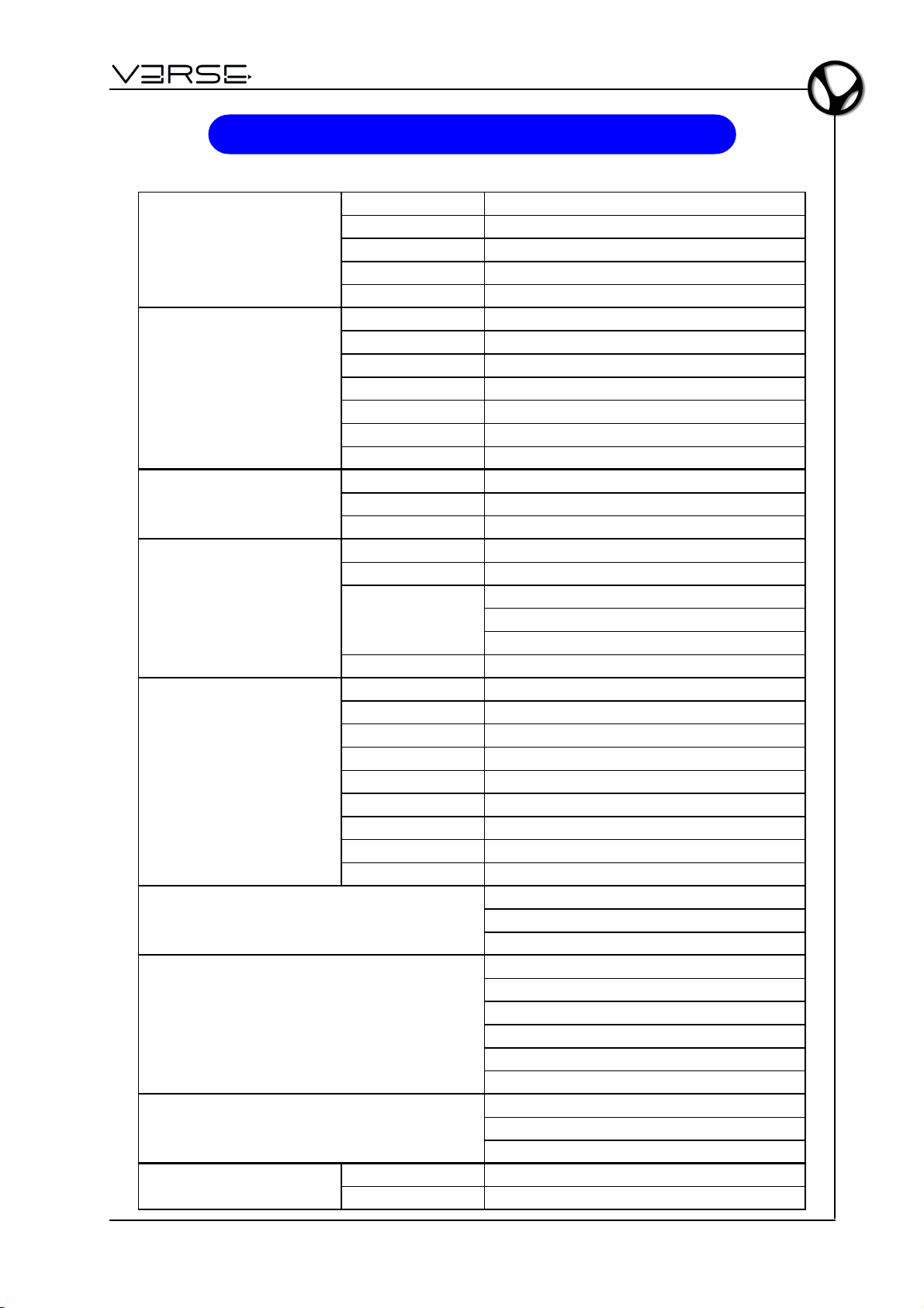
EDGE 500
@
LOW FREQUENCY SECTION
HIGH FREQUENCY SECTION
ACOUSTIC RESPONSE
CONSTRUCTION
AMPLIFIER SECTION
CONTROLS
DISPLAY LEDs
CONNECTORS
PHYSICAL FEATURES
- Manuale Utente
SPECIFICHE TECNICHE
Number of Drivers 2
Woofer Diameter 8 inch / 209 mm
Voice Coil Diameter 2 inch / 50 mm
Winding Material Copper
Magnet Type Ferrite
Number of Drivers 1
Voice Coil Diameter 1.4 inch / 36 mm
Winding Material Aluminium
Throat Diameter 1 inch / 25 mm
Magnet Tipe Ferrite
Horn Design Elliptical Wave Guide
Horn Coverage 90° Horizontal - 60° Vertical
Maximum SPL Peak
Frequency Response 58 Hz ÷ 20 kHz
Crossover frequency 2400Hz
Material Polypropy lene – Composite molded high impact enclosure
Handles 2 on the sides – 1 on the top
Coupling
Protect ions Perforated and painted metal grid
Total Amplifier Power 415W - EIAJ (1kHz, 1% THD)
Max LF output power 350 W
Max HF output power 65 W
Distors ion <0.05% (THD, DIM, SMPTE)
Input sensitivity 0 dBu
Line Input impedance 30 kOhms (balanced) – 15kOhms (unbalanced)
Active protective circuitry Thermal, overload, short circuit, soft clip and voltage limiters
HF protection ptc
Subsonic filter Yes
Dimensions (W x H x D) 355 x 635 x 420 mm
Weight 16 Kg
1m 127 dB
1 hole on the bottom (for speaker stand fitting).
2 M8 screw mounting holes on the sides
1 hook on the rear (for speaker hanging)
Gain
Dynamic loudness
High pass filter
ON (Green Led)
Overload / short c ircuit protection (Red Led)
Thermal protect ion (Red Led)
Compressor high (Red Led)
Compressor low (Red Led)
Signal (Green Led)
Line Input: Female XLR
Link: Male XLR
AC Connector: 3 pin IEC 250 VAC with fuse
IT - 13
Page 32
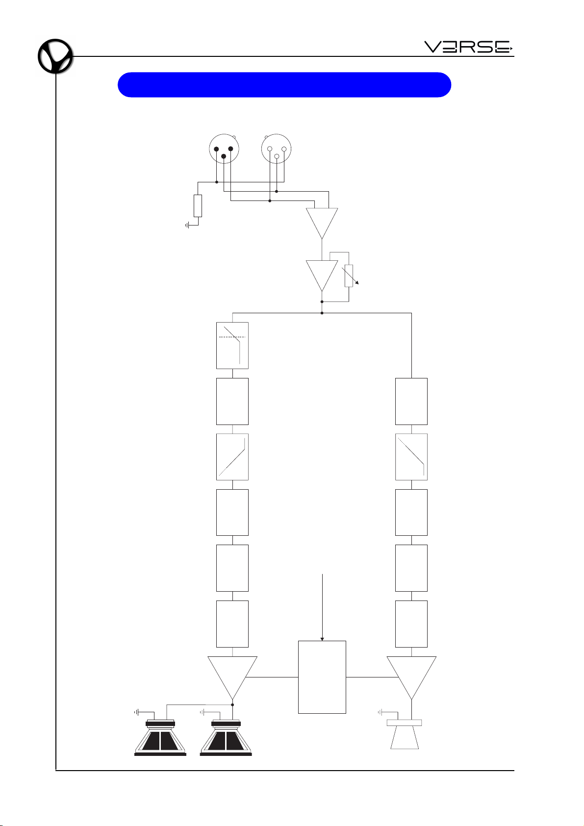
Manuale Utente - EDGE 500
SCHEMA A BLOCCHI
LINE INPUT
LINK
LOAD
123
CHANNEL
DELAY
213
LOW CUT
CROSS-OVER
UNBAL
LINE LEVEL
CHANNEL
DELAY
CROSS-OVER
EQ
GAIN COMP/LIMITER
LO FREQ
AMP
WOOFER
IT - 14
VOLTAGE SENSE
LOW AC
SHORT CIRCUIT
PROTECTIONS
AND THERMAL
CONTINUOUS
VOLTAGE
EQ
GAIN COMP/LIMITER
HI FREQ
AMP
HF DRIVER
Page 33
Smaltimento dei rifiuti elettrici ed elettronici (applicabile nell’Unione Europea e negli altri paesi
europei con servizio di raccolta differenziata)
Ai sensi dell’art. 13 del Decreto legislativo 25 luglio 2005, n. 151 “Attuazione delle Direttive
2002/95/CE, 2002/96/CE e 2003/108/CE”
II simbolo presente sul prodotto o sulla sua confezione indica che il prodotto non verrà trattato come
rifiuto domestico. Sarà invece consegnato al centro di raccolta autorizzato per il riciclo dei rifi uti
elettrici ed elettronici. Assicurandovi che il prodotto venga smaltito in modo adeguato, eviterete un
potenziale impatto negativo sull’ambiente e la salute umana, che potrebbe essere causato da una
gestione non conforme dello smaltimento del prodotto. Il riciclaggio dei materiali contribuirà alla
conservazione delle risorse naturali. Per ricevere ulteriori informazioni più dettagliate Vi invitiamo a
contattare l’uffi cio preposto nella Vostra città, il servizio per lo smaltimento dei rifi uti o il negozio in
cui avete acquistato il prodotto.
Lo smaltimento del prodotto da parte dell’utente comporta l’applicazione delle sanzioni amministrative
previste dalla normativa di legge.
Questo prodotto è conforme ai requisiti delle direttive EMCD 2004/108/EC e LVD 2006/95/EC.
Page 34
Page 35

EDGE 500
- Benutzerhandbuch
INHALT
Wichtige Hinweise ....................................................................................................... 1
Übersicht ..................................................................................................................... 2
Regler und Anschlüsse ................................................................................................ 3
Anschluss-Beispiele .................................................................................................... 5
Komponenten, Konfiguration und Leistungen ............................................................. 8
Positionierung.............................................................................................................. 9
Anwendungs-Vorschläge ........................................................................................... 12
Technische Daten ...................................................................................................... 13
Block-Diagramm ........................................................................................................ 14
WICHTIGE HINWEISE
GEHEN SIE SCHONEND MIT IHREM GERÄT UM
• Wenden Sie bei der Bedienung niemals Gewalt an (Regler, Schalter). Vermeiden sie
beim Transport starke Stöße.
• Belasten sie die Lautsprecher nie übermäßig – nicht während des Transports und
auch nicht während des Betriebs.
• Platzieren Sie die Lautsprecher niemals in der Nähe von Heizungen/Wärmequellen,
in feuchten oder staubigen Räumen oder im Umfeld starker Magnetfelder.
• Platzieren sie die Lautsprecher, falls möglich, nicht in unmittelbaren Umgebung von
Geräten die starke Interferenzen aussenden, so wie Radios, Fernsehgeräte, Monitore
etc. .
• Reinigen Sie die Komponenten nur mit einer weichen Bürste oder Druckluft.
Verwenden Sie niemals alkohol- oder lösungsmittelhaltige Putzmittel.
• Wenn Sie ein Kabel entfernen, sollten Sie immer direkt am Stecker und nicht am
Kabel ziehen. Achten Sie beim Zusammenlegen der Kabel darauf, dass sich keine
Knoten, Verdrehungen oder Schlingen bilden.
• Setzen Sie die Lautsprecher niemals direkter Sonnenbestrahlung aus.
ANSCHLUSS ANS STROMNETZ
• Um das Risiko eines Stromschlags zu vermeiden, sollten Sie die Verbindung mit
dem Netz auf keinen Fall mit nassen oder feuchten Händen herstellen.
• Stellen Sie sicher, dass das von Ihnen verwendete Stromnetz den Vorgaben auf
dem Bedien-Panel entspricht.
• Verbinden Sie die Lautsprecher nur mit geerdeten Steckdosen.
VERBINDUNG MIT EINEM MISCHER
• Verwenden Sie ausschließlich hochwertige, abgeschirmte Kabel.
• Stellen Sie vor dem Anschluss sicher, dass die Lautsprecher auf jeden Fall
ausgeschaltet sind. Auf diese Weise vermeiden Sie laute oder sogar gefährliche
Signal-Spitzen.
IM FALLE EINER FEHLFUNKTION
• Setzen Sie sich im Falle einer Fehlfunktion umgehend mit einem autorisierten ServiceCenter in Verbindung.
DE - 1
Page 36
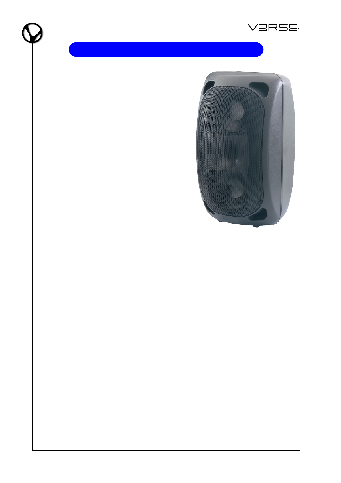
Benutzerhandbuch - EDGE 500
ÜBERSICHT
EDGE 500 ist ein Aktiv- Lautsprecher, bei dem
Technologie, Erfahrung und guter Geschmack in
einem gelungenen Mix von Tonqualität, Leistung
und einfacher Bedienung auf einen Nenner
gebracht wurden. Ausgestattet mit 2 (zwei) 8"
Woofer Custom + 1" Kompressionstreiber und 2
unabhängige Signal-Prozessoren für hohe/niedrige
Frequenzen.
Der Lautsprecher wird unterstützt von einer
Signalverarbeitungskette, einer zweifachen
Verstärkung 350W+65W und einer ausgeklügelten
Akustik,die für eine Perfektionierung der Resultate
bei der Deutlichkeit der akustischen Wiedergabe,
Umfang und Konstanz der Diffusion, Leistung und
Präzision der Verstärkung garantieren.
Das Gehäuse aus PP mit kratzfestem Finish gefällt
mit seinem edlen Design und ist so gebaut, dass
Benutzung und Installation des Lautsprechers in
verschiedenen Stellungen sowohl auf dem Boden
als auch hängend kein Problem darstellen.
EDGE 500 ist die ideale Lösung für alle kleinen
und mittelgroßen Beschallungen, bei denen mit
möglichst wenig Lautsprechern eine optimale Klangversorgung erzielt werden soll.
TECHNOLOGIE
DIGITAL-VERSTÄRKER
Die Digital-Technik hat die Entwicklung professioneller Audio-Verstärker revolutioniert.
Keine andere Technik ist in der Lage mehr Leistung bereit zu stellen – von der Haltbarkeit
mal ganz abgesehen. Die auf ein Minimum reduzierte Wärmeentwicklung und ein
überragendes Leistungs/Gewichtsverhältnis der in VERSE EDGE 500 Boxen
verwendeten Digitalverstärker, sorgen für ein perfektes Handling und enorme
Leistungsreserven. Die Endstufen der Verstärker erreichen eine Effizienz von
unglaublichen 95%. Das heißt in der Praxis, dass nur 5% der verwendeten Energie in
Wärme umgewandelt wird. Der Rest geht im Audiosignal auf. Grundsätzlich hängt die
Effizienz eines Systems nicht zwingend von der Ausgangslautstärke ab. Da die
durchschnittliche Leistungsdichte einer Standardanwendung bei ca. 40% der maximal
zu erreichenden Lautstärke liegt, können konventionell aufgebaute Verstärker ganz leicht
10 mal mehr Hitze erzeugen, als ein VERSE Gerät auf gleichem Lautstärke-Niveau.
Um eine optimale Zuverlässigkeit und Haltbarkeit garantieren zu können, kommen
VERSE Verstärker mit einem Kurzschluss-Schutz, einem Überhitzungs-Schutz mit
thermostatgesteuerter Lüfter-Geschwindigkeit (sorgt dafür, dass die Betriebs- Temperatur
nicht über 60° Celsius steigt) und einer Abschaltautomatik, die den Verstärker deaktiviert,
sobald er ein Wärme-Level erreicht, welches einen Schaden zur Folge haben könnte.
Außerdem haben die VERSE Lautsprecher ein Filter zur Eliminierung extrem
hochfrequenter Signale und Störungen, die den Klang negativ beeinflussen könnten.
Das ITP System (Intelligent Thermal Protect) ist ein Garant für eine optimale Perfomance
und eine lange Lebensdauer der Lautsprecher.
DE - 2
Page 37
EDGE 500
SIGNALVERARBEITUNG
Die verwendeten Prozessoren beinhalten Frequenzweichen und Band-Pass Filter, LevelKompressoren/Limiter, sowie ein Delay zum Phasenabgleich des Systems. Die
Prozessoren arbeiten automatisiert und garantieren so eine optimale Performance und
Betriebssicherheit.
Im Detail: Jeder der beiden Signal-Wege besitzt einen eigenen Limiter, der auf die
Equalizer-Sektion Einfluss nimmt und nicht – wie normalerweise üblich - ausschließlich
auf die Gesamtlautstärke. Vorteil: Da nur die kritischen Frequenzbereiche abgesenkt
werden, bleibt der Sound auch bei eingreifendem Limiter nahezu unverändert.
- Benutzerhandbuch
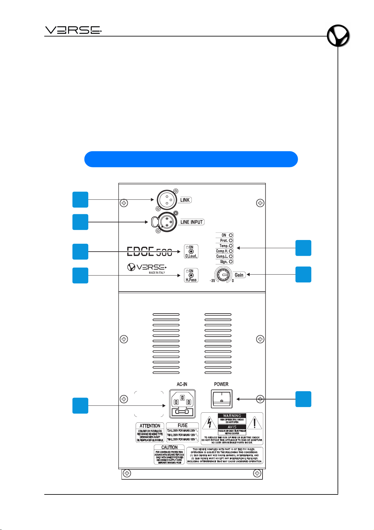
REGLER UND ANSCHLÜSSE
1
2
3
4
5
6
7
8
DE - 3
Page 38

Benutzerhandbuch - EDGE 500
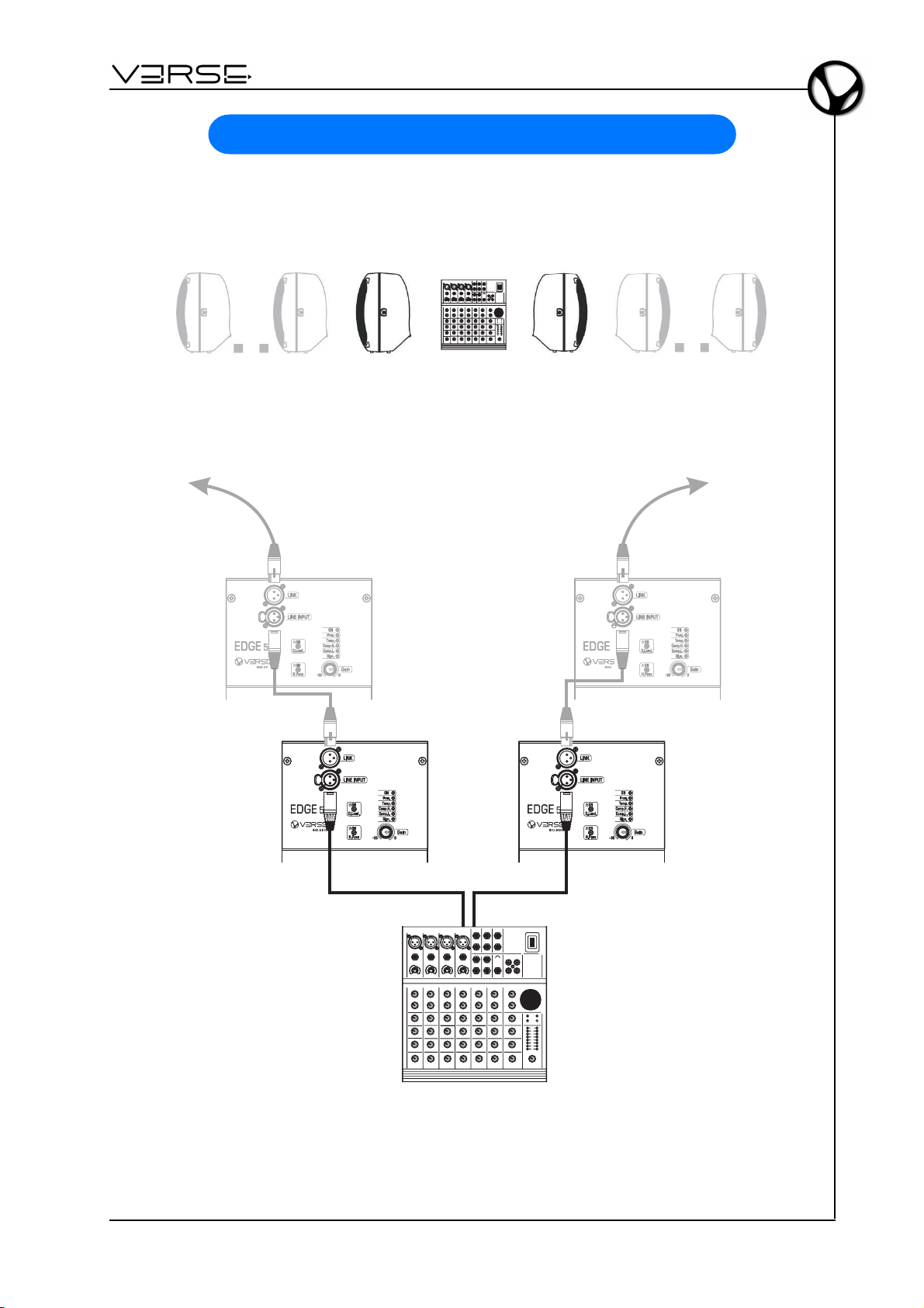
1. Link: liefert das gleiche Signal, das über den Line Input (2) eingespeist wird und
unterstützt so den Anschluss weiterer VERSE Einheiten an ein und dieselbe
Signalquelle.
2. Line Input: symmetrierte XLR Buchse zur Einspeisung des zu verstärkenden Signals.
3. D.Loud.: aktiviert eine dynamische Klangregelung die dazu dient, eine natürliche
Limitierungen des menschlichen Gehörs zu kompensieren ( Abnahme der Bassund
Höhen-Wahrnehmung bei größer werdenden Lautstärken). Die Klangregelung arbeitet
dynamisch, das heißt es findet, abhängig von der jeweils eingestellten
Gesamtlautstärke, eine kontinuierliche Anpassung des gelieferten Frequenzspektrums
statt die dabei hilft, die natürliche Limitierung des menschlichen Gehörs zu
kompensieren.
4. H.Pass: aktiviert ein Hochpass-Filter und bereitet das Signal so optimal auf die
Verwendung von Subwoofer. Ist die Schaltung deaktiviert, verhalten sich die
integrierten Lautsprecher wie Full-Range Speaker, eingeschaltet arbeiten sie wie die
Satelliten-Boxen der Subwoofer.
5. AC-IN: Buchse für das Netzkabel. Die Buchse ist mit einer Schmelzsicherung in
einem geschützten Fach ausgestattet. Gehen Sie zum Auswechseln der Sicherung
genau wie folgt vor:
- Schalten Sie das Gerät aus;
- Entfernen Sie das Netzkabel;
- Öffnen Sie das Türchen des Sicherungsfaches mit einem Schraubendreher;
- Ersetzen Sie die alte durch eine neue, identische Sicherung: T2A L 250V bei der
Version 230 VAC oder T4A L 250V bei den Versionen 120 VAC und 100 VAC;
- Schließen Sie das Türchen wieder.
6. LED’s:
- ON: leuchtet bei eingeschaltetem Lautsprecher.
- Prot.: zeigt an, dass der Verstärker wegen eines internen Fehlers oder eines Fehlers
in einem der angeschlossenen Lautsprecher, in den Schutzmodus geschaltet hat
(bitte rufen Sie in einem solchen Fall die Telefon-Hotline an).
- Temp.: zeigt an, dass der integrierte Verstärker wegen Überhitzung in den
Schutzmodus geschaltet hat. In dieser Einstellung liefert der Verstärker nur noch
die halbe Leistung. Bitte reduzieren sie das Eingangs-Level und erlauben dem
Verstärker so, die normalen Betriebs- Bedingungen wieder herzustellen.
- Comp. H.: zeigt Aktivitäten des High-Frequency-Kompressors an. Wenn das Signal
eine Sicherheitsmarke überschreitet, garantiert der Kompressor eine gute
Klangqualität ohne akustische Verzerrungen, indem er ausschließlich die
verzerrenden Frequenz dämpft. Das System arbeitet absolut sicher. Leuchtet die
LED permanent, sollte die Stärke des Eingangssignals reduziert werden.
- Comp. L.: zeigt Aktivitäten des Bass-Kompressors an. Wenn das Signal eine
Sicherheitsmarke überschreitet, garantiert der Kompressor eine gute Klangqualität
ohne akustische Verzerrungen, indem er ausschließlich die verzerrenden
Frequenzen dämpft. Das System arbeitet absolut sicher. Leuchten die LED
permanent, sollte die Stärke des Eingangssignals reduziert werden.
- Sign.: zeigt ein anliegendes Signal an.
7. Gain: reguliert die Signal-Vorverstärkung in einem Bereich zwischen -35dB und 0dB.
8. POWER: Schaltet das Gerät ein/aus.
DE - 4
Page 39
EDGE 500
G
A
I
N
L
I
N
E
I
M
C
G
A
I
N
S
E
N
S
I
T
I
V
I
T
Y
L
I
N
E
G
A
I
N
L
I
N
E
I
M
C
G
A
I
N
S
E
N
S
I
T
I
V
I
T
Y
L
I
N
E
-10dB
+10-30
-50dB
G
A
I
N
L
I
N
E
I
M
C
G
A
I
N
S
E
N
S
I
T
I
V
I
T
Y
L
I
N
E
-10dB
+10-30
-50dB-10dB
+10-30
-50dB
G
A
I
N
L
I
N
E
I
M
C
G
A
I
N
S
E
N
S
I
T
I
V
I
T
Y
L
I
N
E
G
A
I
N
L
I
N
E
I
M
C
G
A
I
N
S
E
N
S
I
T
I
V
I
T
Y
L
I
N
E
-10dB
+10-30
-50dB
G
A
I
N
L
I
N
E
I
M
C
G
A
I
N
S
E
N
S
I
T
I
V
I
T
Y
L
I
N
E
-10dB
+10-30
-50dB-10dB
+10-30
-50dB
G
A
I
N
L
I
N
E
I
M
C
G
A
I
N
S
E
N
S
I
T
I
V
I
T
Y
L
I
N
E
G
A
I
N
L
I
N
E
I
M
C
G
A
I
N
S
E
N
S
I
T
I
V
I
T
Y
L
I
N
E
-10dB
+10-30
-50dB
G
A
I
N
L
I
N
E
I
M
C
G
A
I
N
S
E
N
S
I
T
I
V
I
T
Y
L
I
N
E
-10dB
+10-30
-50dB-10dB
+10-30
-50dB
G
A
I
N
L
I
N
E
I
M
C
G
A
I
N
S
E
N
S
I
T
I
V
I
T
Y
L
I
N
E
G
A
I
N
L
I
N
E
I
M
C
G
A
I
N
S
E
N
S
I
T
I
V
I
T
Y
L
I
N
E
-10dB
+10-30
-50dB
G
A
I
N
L
I
N
E
I
M
C
G
A
I
N
S
E
N
S
I
T
I
V
I
T
Y
L
I
N
E
-10dB
+10-30
-50dB-10dB
+10-30
-50dB
G
A
I
N
L
I
N
E
I
M
C
G
A
I
N
S
E
N
S
I
T
I
V
I
T
Y
L
I
N
E
G
A
I
N
L
I
N
E
I
M
C
G
A
I
N
S
E
N
S
I
T
I
V
I
T
Y
L
I
N
E
-10dB
+10-30
-50dB
G
A
I
N
L
I
N
E
I
M
C
G
A
I
N
S
E
N
S
I
T
I
V
I
T
Y
L
I
N
E
-10dB
+10-30
-50dB-10dB
+10-30
-50dB
G
A
I
N
L
I
N
E
I
M
C
G
A
I
N
S
E
N
S
I
T
I
V
I
T
Y
L
I
N
E
G
A
I
N
L
I
N
E
I
M
C
G
A
I
N
S
E
N
S
I
T
I
V
I
T
Y
L
I
N
E
-10dB
+10-30
-50dB
G
A
I
N
L
I
N
E
I
M
C
G
A
I
N
S
E
N
S
I
T
I
V
I
T
Y
L
I
N
E
-10dB
+10-30
-50dB-10dB
+10-30
-50dB
G
A
I
N
L
I
N
E
I
M
C
G
A
I
N
S
E
N
S
I
T
I
V
I
T
Y
L
I
N
E
G
A
I
N
L
I
N
E
I
M
C
G
A
I
N
S
E
N
S
I
T
I
V
I
T
Y
L
I
N
E
-10dB
+10-30
-50dB
G
A
I
N
L
I
N
E
I
M
C
G
A
I
N
S
E
N
S
I
T
I
V
I
T
Y
L
I
N
E
-10dB
+10-30
-50dB-10dB
+10-30
-50dB
G
A
I
N
L
I
N
E
I
M
C
G
A
I
N
S
E
N
S
I
T
I
V
I
T
Y
L
I
N
E
G
A
I
N
L
I
N
E
I
M
C
G
A
I
N
S
E
N
S
I
T
I
V
I
T
Y
L
I
N
E
-10dB
+10-30
-50dB
G
A
I
N
L
I
N
E
I
M
C
G
A
I
N
S
E
N
S
I
T
I
V
I
T
Y
L
I
N
E
-10dB
+10-30
-50dB-10dB
+10-30
-50dB
- Benutzerhandbuch
ANSCHLUSS-BEISPIELE
MIXER + 2 (oder mehrere) EDGE 500 - STEREO
LEFT RIGHT
Left Out Right Out
MIXER
DE - 5
Page 40
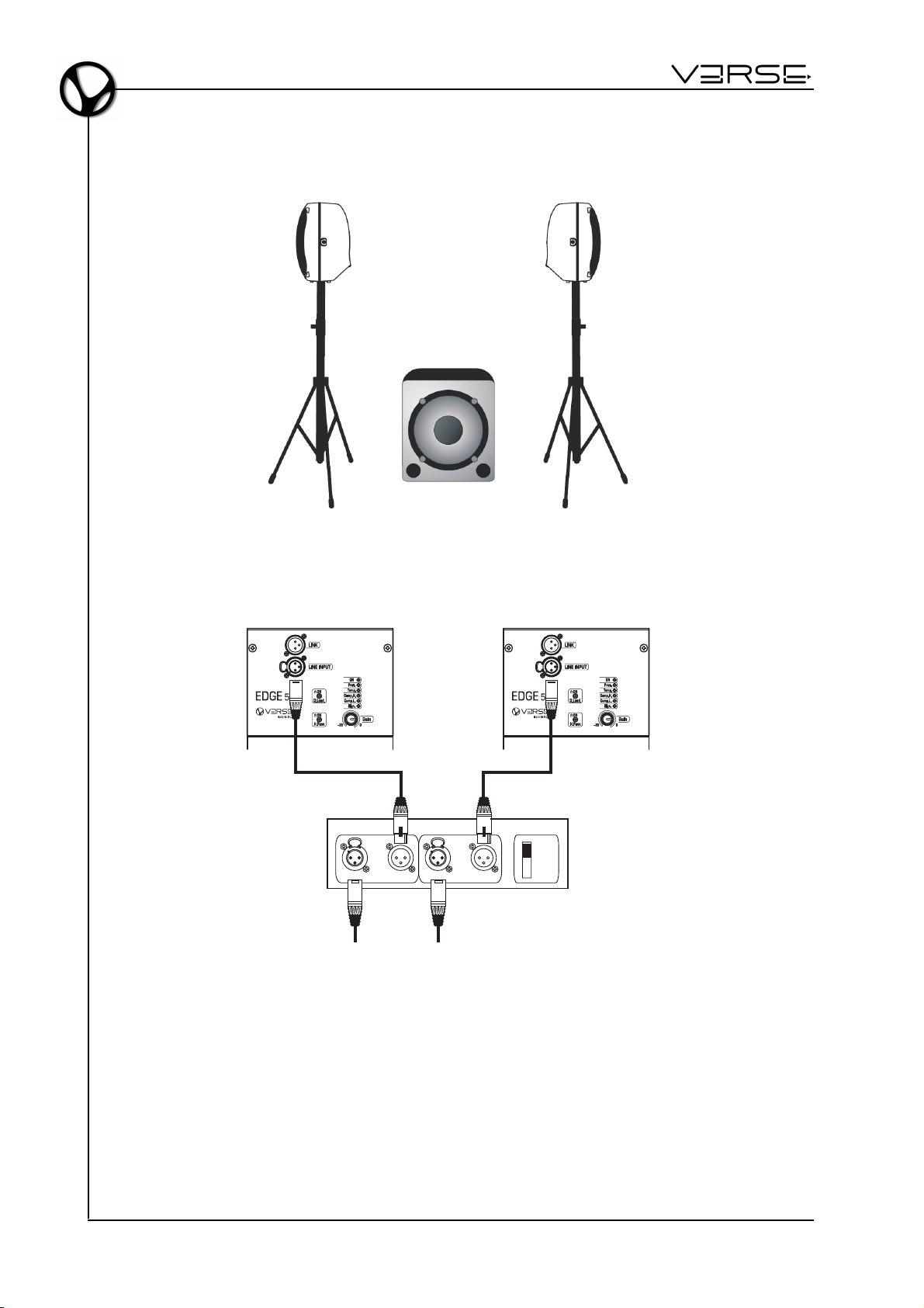
Benutzerhandbuch - EDGE 500
1 ACTIVE SUB + 2 EDGE 500 - STEREO
LEFT RIGHT
Left/Mono Right
Stereo
Input Link Input Link
Left
Source
Signal
Right
Source
Signal
ACTIVE SUB-WOOFER
Mono
DE - 6
Page 41
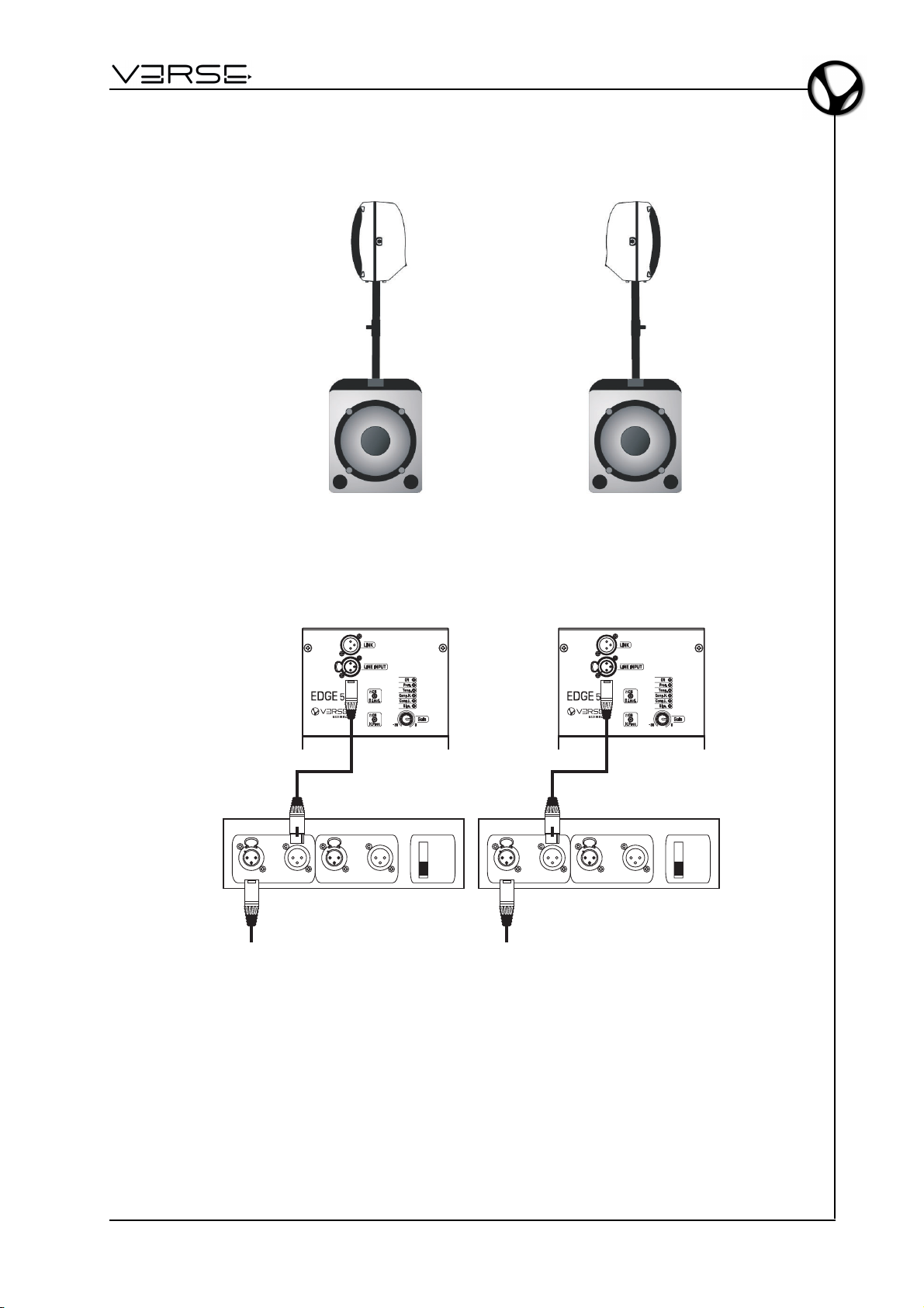
EDGE 500
- Benutzerhandbuch
2 ACTIVE SUB + 2 EDGE 500 - STEREO
Left/Mono Right
Input Link Input Link
ACTIVE SUB-WOOFER
Left
Source
Signal
LEFT RIGHT
Left/Mono Right
Stereo
Mono
Input Link Input Link
ACTIVE SUB-WOOFER
Right
Source
Signal
Stereo
Mono
DE - 7
Page 42
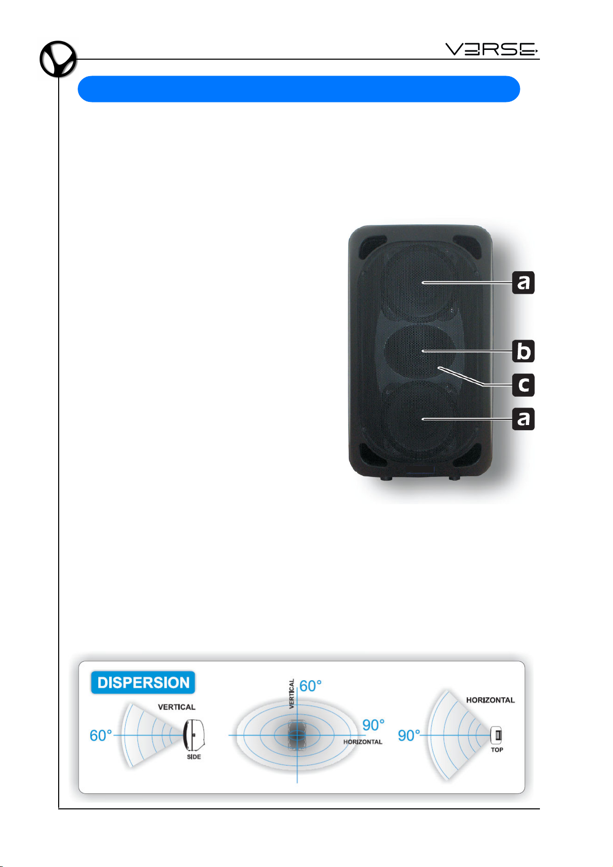
Benutzerhandbuch - EDGE 500
KOMPONENTEN, KONFIGURATION UND LEISTUNG
Der Diffusionsbereich verwendet hoch-effektive, maßgeschneiderte Geräte in folgender
Konfiguration: 2 8" Woofer + 1" Kompressionstreiber. Der Anschluss dieser Elemente
bietet erhebliche Vorteile sowohl bezüglich Zuverlässigkeit wie auch akustischer Leistung,
speziell in der Wiedergabe des Stimmenbereichs. Einige Beispiele:
a. Der 2-fache 8" Woofer reduziert die
aufeinander einwirkenden Massen um 30%
verglichen mit herkömmlicher Konfiguration
mit einem einzigen 12" Lautsprecher.
Das führt zu einem höheren
Beschleunigungsfaktor (schnelleres
Einschwingverhalten), unfassenderer
Ausdehnung hin zu den tieferen Frequenzen
und damit besserer akustischer Kontinuität
zwischen niedrigen/hohen Komponenten
des Systems.
b. Die Verwendung eines 1" HF-Treibers gemäß
neuester Technologien und mit einer
Polyestere-Membrane ausgestattet ist für
deutlich effizientere Hochfrequenz-Weitergabe
(106 dB), breitere Frequenzausdehnung,
besseren Beschleunigungsfaktor und größere
Zuverlässigkeit verantwortlich.
c. Der HF-Treiber ist auf einem elliptischen
Schwingungs-Schallfänger montiert, der frei
von akustischer Resonanz und gleichzeitig einen breiten Streuwinkel bietet, selbst
außerhalb der Achse und einer besonderen Verständlichkeit mittelhoher und hoher
Frequenzbereiche ist.
All diese Charakteristiken erlauben eine akustische Stimmigkeit, die:
- dem Pubikum eine gleichbleibende Klangqualität unabhängig vom Standort und
- den Künstlern ein gleichmäßiges Hörgefühl, unabhähgig davon, ob der Diffusor
senkrecht oder geneigt (Monitor) aufgestellt ist, gibt.
DE - 8
Page 43
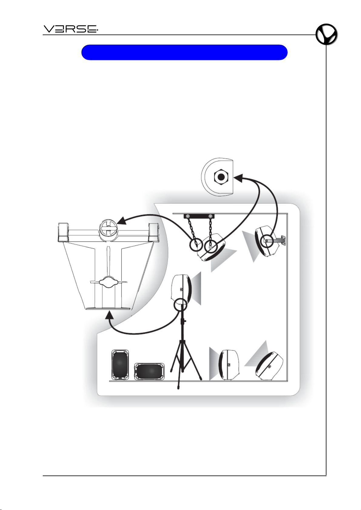
EDGE 500
- Benutzerhandbuch
POSITIONIERUNG
Das Design und die mechanischen Ausstattungen des Gehäuses des EDGE 500 machen
die Benutzung und die Installation des Lautsprechers extrem praktisch:
- auf dem Boden: vertikal, horizontal oder schräg Monitor-Benutzung
- hängend: auf Stativ/Ständer, an der Wand befestigt oder an einem Gerüst hängend.
Die spezielle Konfiguration der Komponenten gewährleistet immer eine korrekte
Klangverteilung.
DE - 9
Page 44

Benutzerhandbuch - EDGE 500
SICHERHEITSEMPFEHLUNG FÜR DISTANZSTANGEN UND STATIVE
Dieses Handbuch setzt voraus, dass die Besitzer und/oder Benutzer eines VERSE
Systems Kenntnisse und Erfahrungen auf dem Gebiet Stativbenutzung mit
Lautsprechersystemen besitzen.
Das Aufhängen großer schwerer Gegenstände an Distanzstangen oder Stative an
öffentlichen Orten unterliegt zahlreichen Gesetzen und Regelungen auf den National-/
Bundes-, Staats-/Landes- und örtlichen Ebenen, auf die wir in diesem Handbuch nicht
eingehen werden. Trotzdem muss der Benutzer verantwortlich sicherstellen, dass die
Verwendung von jeglichen VERSE Systemen, deren Komponenten und allen Ständern
und Distanzstangen und dazu gehörigen Hardware unter allen Umständen und in allen
Orten allen zutreffenden Gesetzen und Regelungen entspricht, die jeweils zu dem
Zeitpunkt Gültigkeit haben.
BEI DER BENUTZUNG VON STÄNDERN UND DISTANZSTANGEN BITTE DIE
FOLGENDEN VORSICHTSMAßNAHMEN BEACHTEN:
DIE SPEZIFIKATIONEN DES STÄNDERS ODER DER DISTANZSTANGE
ÜBERPRÜFEN, UM SICHERZUSTELLEN, DASS DAS GERÄT DAFÜR KONZIPIERT
IST, DIE LAST DES LAUTSPRECHERS ZU TRAGEN.
BITTE BEFOLGEN SIE ALLE VORSICHTSMAßNAHMEN DES HERSTELLERS ZUR
GEWÄHRLEISTUNG DER SICHERHEIT.
STELLEN SIE SICHER, DASS DIE OBERFLÄCHE, AUF DER DAS SYSTEM
GESTAPELT WERDEN SOLL, EBEN, STABIL UND OHNE GEFÄLLE IST.
LEITEN SIE DIE KABEL SO, DASS WEDER KÜNSTLER, DAS PRODUKTIONSTEAM
NOCH DAS PUBLIKUM DARÜBER STOLPERN KÖNNEN UND DEN LAUTSPRECHER
UMKIPPEN.
PRÜFEN SIE DEN STÄNDER (ODER DIE DISTANZSTANGE UND DIE ZUGEHÖRIGE
HARDWARE) VOR JEDEM GEBRAUCH UND VERWENDEN SIE KEINE GERÄTE
MIT ABGENUTZTEN, BESCHÄDIGTEN ODER FEHLENDEN TEILEN.
VERSUCHEN SIE NICHT MEHR ALS EINEN VERSE EDGE 500 LAUTSPRECHER
AUF EINEN STÄNDER ODER EINE DISTANZSTANGE ZU STELLEN/MONTIEREN.
SEIEN SIE IMMER VORSICHTIG WENN SIE DAS SYSTEM IM FREIEN AUFSTELLEN,
UNERWARTETE WINDBÖEN KÖNNEN EIN SYSTEM UMKIPPEN. ES KANN
NOTWENDIG WERDEN, ZUSÄTZLICHE GEWICHTE (Z. B. SANDSÄCKE) AM FUß
DES STÄNDERS ZU PLATZIEREN, UM DESSEN STABILITÄT ZU VERBESSERN.
BEFESTIGEN SIE KEINE FAHNEN ODER ÄHNLICHES AN IRGENDEINEM TEIL EINES
DER LAUTSPRECHERSYSTEME. SOLCHE ZUSÄTZE KÖNNTEN ALS SEGEL
FUNGIEREN UND STABILITÄT STARK GEFÄHRDEN.
FALLS SIE NICHT SICHER SIND, DASS SIE DAS GEWICHT DES LAUTSPRECHERS
ALLEIN BEWÄLTIGEN KÖNNEN, BITTEN SIE JEMAND, IHNEN DABEI ZU HELFEN,
DIESEN AUF DEN DREIFUßSTÄNDER ODER DIE DISTANZSTANGE ZU HEBEN.
Wenn man die VERSE Lautsprecher auf einem Stativ montiert, muss sichergestellt sein,
dass das System stabil steht um ein Kippen zu vermeiden. Die Stabilität wird durch die
Höhe der Platzierung des Lautsprechers und die Ausbreitung der Füße bestimmt.
Da die Benutzer für eine korrekte Aufstellung und eine genaue Stabilitätsprüfung
verantwortlich gemacht werden, könnte folgendes als Referenz hilfreich sein: Bei
Verwendung eines Stativs mit mindestens 168 cm Fußbreite, kann man den Lautsprecher
bis auf 180 cm Höhe platzieren.
DE - 10
Page 45

EDGE 500
Wenn man VERSE Lautsprecher auf eine Distanzstange im Zusammenhang mit einem
dazugehörigen Subwoofer aufstellt, hängt die maximale Höhenplatzierung des Satelliten
von den Abmessungen des Subwoofer ab. Vorausgesetzt, dass Benutzer zur
Verantwortung bezüglich der korrekten Installation und genauem Stabilitätskontrolle
beauftragt werden, können diese Hinweisrichtlinien aus folgender Tabelle entnommen
werden:
- SUB 10 MKII: no
- SUB 15 MKII: max 90 cm
- SUB 18 MKII: max 135 cm
- SUB 215 MKII: max 130 cm
SICHERHEITSEMPFEHLUNGEN BEI „HÄNGENDER MONTAGE“
In dieser Bedienungsanleitung gehen wir davon aus, dass die Besitzer und/oder User
eines Verse-Systems bereits Erfahrungen im Aufbau und der „hängenden“ Montage
von Lautsprecher-Systemen haben.
Das Aufhängen von großen, schweren Objekten in öffentlich zugänglichen Bereichen
wird in den einzelnen Ländern durch zahllose Gesetze und Regularien geregelt. Diese
haben wir in dieser Bedienungsanleitung nicht abgedruckt.
Der User übernimmt die volle Verantwortung dafür, dass die Montage des Verse-Systems
und seiner Komponenten konform zu den jeweils anzuwendenden Gesetzen und
Sicherheitsempfehlungen des Landes geschieht, in dem die Montage stattfindet.
- Benutzerhandbuch
VIELE DER FÜR EINEN SICHEREN BETRIEB ENTSCHEIDENDEN ASPEKTE, WIE
ZUM BEISPIEL DER TECHNISCHE UND MECHANISCHE ZUSTAND DER VOR ORT
ANGEBOTENEN MONTAGE-PUNKTE ODER DEREN GRUNDSÄTZLICHE EIGNUNG,
KÖNNEN IN DIESER BEDIENUNGSANLEITUNG NICHT BERÜCKSICHTIGT
WERDEN.
DER BENUTZER ÜBERNIMMT DIE VOLLE VERANTWORTUNG FÜR DEN EINSATZ
EINES VERSE-SYSTEMS AN ALLEN ERDENKLICHEN ORTEN UND IN ALLEN
ERDENKLICHEN UMSTÄNDEN.
DER BENUTZER EINES VERSE-SYSTEMS IST VERANTWORTLICH DAFÜR, DASS
BEIM AUFBAU ALLE VOM JEWEILIGEN GESETZGEBER FESTGELEGTEN
REGULARIEN UND MASSNAHMEN BERÜCKSICHTIGT WERDEN.
Um eine sichere Montage des Systems zu gewährleisten, sollte man im Vorfeld alle
Haltepunkte an den Boxen einer intensiven Inspektion unterziehen. Das Gleiche gilt
auch für die Montage an vor Ort angebotenen Montagehilfen wie Installations-Punkten
an Decken etc. - gerade dann, wenn sie im Rahmen von Konzerten regelmäßig verwendet
werden. Auch Stative sollten vor der Montage intensiv in Augenschein genommen werden.
Verse-Systeme sollten nur aufgehängt werden wenn sicherheitsgeprüfte InstallationsPunkte angeboten werden, die in der Lage sind das Gewicht der Komponenten sicher
zu halten. Ist das nicht der Fall, sollte unbedingt Abstand von einer hängenden Montage
genommen werden.
DE - 11
Page 46

Benutzerhandbuch - EDGE 500
ANWENDUNGS-VORSCHLÄGE
Die akustischen Eigenschaften eines Raums haben einen maßgeblichen Einfluss auf
den von einem Soundsystem produzierten Gesamtklang. Dank der technischen
Ausstattung (wie z.B. der optimalen Breite des Abstrahlbereichs) können mit EDGE 500
Boxen die meisten üblichen negativen Raum-Eigenschaften minimiert oder sogar komplett
kompensiert werden. Die Merkmale helfen dabei, das Ergebnis zu optimieren.
• Platzieren Sie die Boxen nie in den Ecken eines Raums oder in Nischen. Dies kann
zu einer unangenehmen Verstärkung tiefer Frequenzen führen. Das Resultat ist ein
„verwaschener“, undifferenzierter Klang.
• Stellen Sie die Boxen nicht in Richtung Wand auf. Auch dies führt zu einer Verstärkung
tiefer Frequenzen. In Maßen eingesetzt lässt sich diesem Effekt aber auch etwas
Positives abgewinnen. So hat man die Option dünn klingenden Sounds durch
vorsichtiges Drehen der Boxen in Richtung Wand, mehr Fülle und Druck zu verleihen.
• Vermeiden Sie das direkte Aufstellen der Boxen auf Untergründen die einen
Resonanzraum bieten. Dies kann zu Interferenzen und Feedbacks führen. Die besten
Ergebnisse lassen sich in solchen Fällen erzielen, wenn Sie von vornherein BoxenStänder verwenden.
• Denken Sie daran, dass sich hohe Frequenzen im Vergleich zu Bässen, wesentlich
zielgerichteter ausbreiten und dabei eine höhere Absorbtionsrate besitzen. Um
garantieren zu können, dass das Signal den Zuhörer auch ausreichend stark erreicht,
müssen die Boxen so aufgestellt werden, dass sie in direkter Linie mit den Köpfen
der Zuhörer abstrahlen (ungefähr einen halben Meter/einen Meter über den Köpfen).
• In Gebäuden mit intensivem Hall (Kirche, Aula, Halle etc.) ist es empfehlenswert mit
Dämmmaterialien wie Teppichen, Gardinen etc. zu arbeiten. Sollte das nicht möglich
(oder nicht ausreichend) sein, erhöhen Sie zur Erzielung eines besseres Ergebnisses
auf keinen Fall einfach nur die Lautstärke. Dies würde zu einer Verstärkung der
Reflektionen und damit einer weiteren Verschlechterung des Sounds führen. Die
beste Lösung liegt im Einsatz mehrerer Boxen, die im gesamten Raum verteilt werden
(z.B. vorne+hinten; vorne+seitlich; vorne+seitlich+hinten).
DE - 12
Page 47
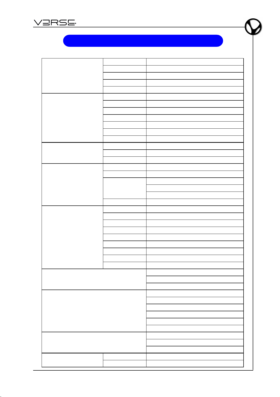
EDGE 500
@
LOW FREQUENCY SECTION
HIGH FREQUENCY SECTION
ACOUSTIC RESPONSE
CONSTRUCTION
AMPLIFIER SECTION
CONTROLS
DISPLAY LEDs
CONNECTORS
PHYSICAL FEATURES
- Benutzerhandbuch
TECHNISCE DATEN
Number of Drivers 2
Woofer Diameter 8 inch / 209 mm
Voice Coil Diameter 2 inch / 50 mm
Winding Material Copper
Magnet Type Ferrite
Number of Drivers 1
Voice Coil Diameter 1.4 inch / 36 mm
Winding Material Aluminium
Throat Diameter 1 inch / 25 mm
Magnet Tipe Ferrite
Horn Design Elliptical Wave Guide
Horn Coverage 90° Horizontal - 60° Vertical
Maximum SPL Peak
Frequency Response 58 Hz ÷ 20 kHz
Crossover frequency 2400Hz
Material Polypropy lene – Composite molded high impact enclosure
Handles 2 on the sides – 1 on the top
Coupling
Protect ions Perforated and painted metal grid
Total Amplifier Power 415W - EIAJ (1kHz, 1% THD)
Max LF output power 350 W
Max HF output power 65 W
Distors ion <0.05% (THD, DIM, SMPTE)
Input sensitivity 0 dBu
Line Input impedance 30 kOhms (balanced) – 15kOhms (unbalanced)
Active protective circuitry Thermal, overload, short circuit, soft clip and voltage limiters
HF protection ptc
Subsonic filter Yes
Dimensions (W x H x D) 355 x 635 x 420 mm
Weight 16 Kg
1m 127 dB
1 hole on the bottom (for speaker stand fitting).
2 M8 screw mounting holes on the sides
1 hook on the rear (for speaker hanging)
Gain
Dynamic loudness
High pass filter
ON (Green Led)
Overload / short c ircuit protection (Red Led)
Thermal protect ion (Red Led)
Compressor high (Red Led)
Compressor low (Red Led)
Signal (Green Led)
Line Input: Female XLR
Link: Male XLR
AC Connector: 3 pin IEC 250 VAC with fuse
DE - 13
Page 48
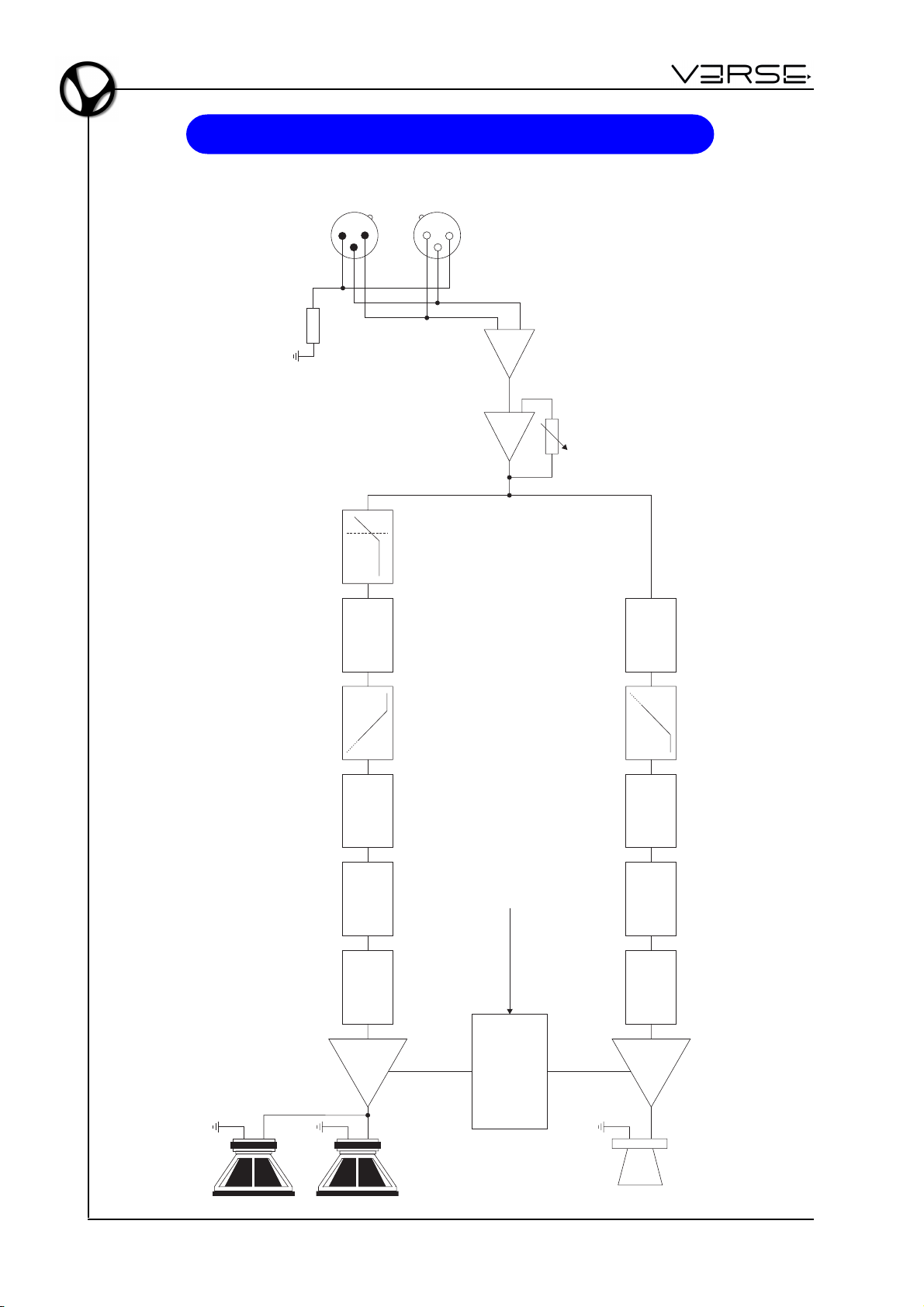
Benutzerhandbuch - EDGE 500
BLOCK-DIAGRAMM
LINE INPUT
LINK
LOAD
123
CHANNEL
DELAY
213
LOW CUT
CROSS-OVER
UNBAL
LINE LEVEL
CHANNEL
DELAY
CROSS-OVER
EQ
GAIN COMP/LIMITER
LO FREQ
AMP
WOOFER
DE - 14
VOLTAGE SENSE
LOW AC
SHORT CIRCUIT
PROTECTIONS
AND THERMAL
CONTINUOUS
VOLTAGE
EQ
GAIN COMP/LIMITER
HI FREQ
AMP
HF DRIVER
Page 49
Entsorgung von alten Elektro- und Elektronikgeräten (gültig in der Europäischen Union und
anderen europäischen Ländern mit separatem Sammelsystem)
Dir. 2002/95/CE, 2002/96/CE e 2003/108/CE
Dieses Symbol auf dem Produkt oder auf der Verpackung bedeutet, dass dieses Produkt nicht wie
Hausmüll behandelt werden darf. Stattdessen soll dieses Produkt zu dem geeigneten
Entsorgungspunkt zum Recyclen von Elektro- und Elektronikgeräten gebracht werden. Wird das
Produkt korrekt entsorgt, helfen Sie mit, negativen Umwelteinfl üssen und Gesundheitsschäden
vorzubeugen, die durch unsachgemäße Entsorgung verursacht werden könnten; Das Recycling von
Material wird unsere Naturressourcen erhalten. Für nähere informationen über das Recyclen dieses
Produktes kontaktieren Sie bitte Ihr lokales Bürgerbüro, Ihren Abholservice oder das Geschäft, in dem
Sie dieses Produkt gekauft haben.
Dieses Produkt entspricht mit den Anforderungen von EMCD 2004/108/EC und LVD 2006/95/EC.
Page 50

®
VERSE
is a registered trade mark – Viscount International SpA
Via Borgo 68/70 – 47836 Mondaino (Rimini) Italy – Tel +39 0541 981700 – Fax +39 0541 981052
www.viscountinstruments.com
Le informazioni contenuto nel presente documento sono state redatte e controllate con attenzione. Tuttavia VISCOUNT
INTERNATIONAL S.p.A. declina ogni responsabilità in merito ad eventuali inesattezze. Tanto le informazioni contenute in questo
documento, quanto le specifiche dei prodotti ai quali fa riferimento sono soggette a modifiche senza preavviso. VISCOUNT
INTERNATIONAL S.p.A. non assume alcuna responsabilità sull’uso o sull’applicazione dei prodotti descritti in questo documento. Ogni
eventuale citazione di nomi, prodotti e società ha il solo scopo di illustrare l’uso dei prodotti qui descritti. Nomi, logo e marchi
eventualmente riportati appartengono ai rispettivi proprietari. Tutti i diritti sono riservati e nessuna parte di questo documento può
essere riprodotta in alcuna forma, in alcun modo e per alcuno scopo senza il permesso scritto di VISCOUNT INTERNATIONAL S.p.A.
The information in this document has been drafted and checked with care. However VISCOUNT INTERNATIONAL S.p.A. declines all
responsability for any inaccurancies. Both the information in this document and the product specifications to which in refers are
subject to amendment without notice. VISCOUNT INTERNATIONAL S.p.A. does not accept any responsability with regard to the use or
application of the products described in this document. Any references to names, products and companies is for the sole purpose of
illustrating the use of the products described herein. Any names, logos and brands referred to belong to their respective owners. All
rights reserved; the reproduction of any part of this document, in any form and for any purporse without VISCOUNT INTERNATIONAL
S.p.A.’s specific written permission is forbidden
 Loading...