


i
VX-GPF1626
Quick Installation Guide
2016, Versa Technology Corporation. All rights reserved. All brand and product names are
trademarks or registered trademarks of their respective companies

ii
Contents
Chapter 1 Introduction ........................................................................ 1
Overview ........................................................................................................................................1
Front panel of the Switch .........................................................................................................1
Rear panel of the Switch ...........................................................................................................2
Chapter 2 Installing The Switch ......................................................... 3
Package Contents .......................................................................................................................4
Mounting the Switch in a 19-inch Rack ..............................................................................4
Mounting the Switch on Desk or Shelf ...............................................................................5
Connecting the AC Power Cord .............................................................................................6
Installing SFP Modules ..............................................................................................................7
Connecting Console Port .........................................................................................................7
Chapter 3 Managing Switch Using the Web Interface .................... 8
Manage the Switch Using Web Browser.............................................................................8
Chapter 4 Troubleshooting ................................................................ 9
Appendix A Technical Specifications ................................................. 10
Hardware Specification .......................................................................................................... 10
1000 MBPS Gigabit Ethernet Collision Domain ............................................................ 11
1
Chapter 1 Introduction
Overview
The VX-GPF1626 is an IEEE-compliant, 26-port PoE GbE Web Smart+ Switch with powerful
management features that will boost your network’s performance.
This guide describes hardware installation and basic troubleshooting for the unit.
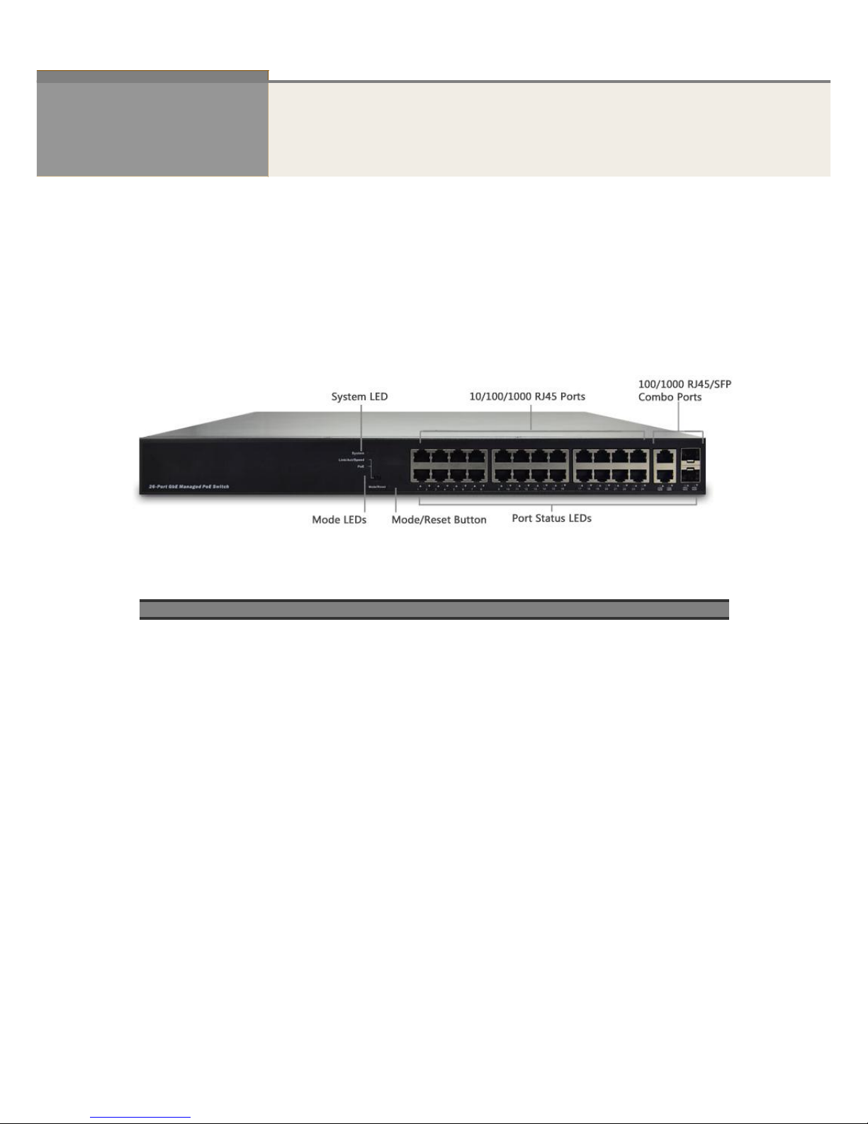
Front panel of the Switch
Figure 1 Front panel of the switch
Table 1 Port Status LEDs
LED
Condition
Status
TP (Link/Act/Speed)
Green/Blink
Lit Green when TP links on 1000Mbps
Amber when TP links on 10/100Mbps
TP (PoE)
Green/Off
Lit Green when PoE links are functioning
SFP (Link/Act/Speed)
Green/Blink
Lit Green when SFP links are functioning
Lit Green when SFP links are 1000Mbps.
Amber when SFP links are 100Mbps
2
Table 2 System Status LED
SYSTEM LED
Condition
status
System
Green
OFF
Lit when power is coming up
Table 3 Mode Status LED
LED
Condition
Status
Link/ACT/Speed
Green
Yellow
OFF
Green when the link is 1000Mbps
Yellow when the link is 100Mbps
Off when the link is 10Mbps
PoE
Green
OFF
Lit Green when LEDs of each port are in PoE Mode
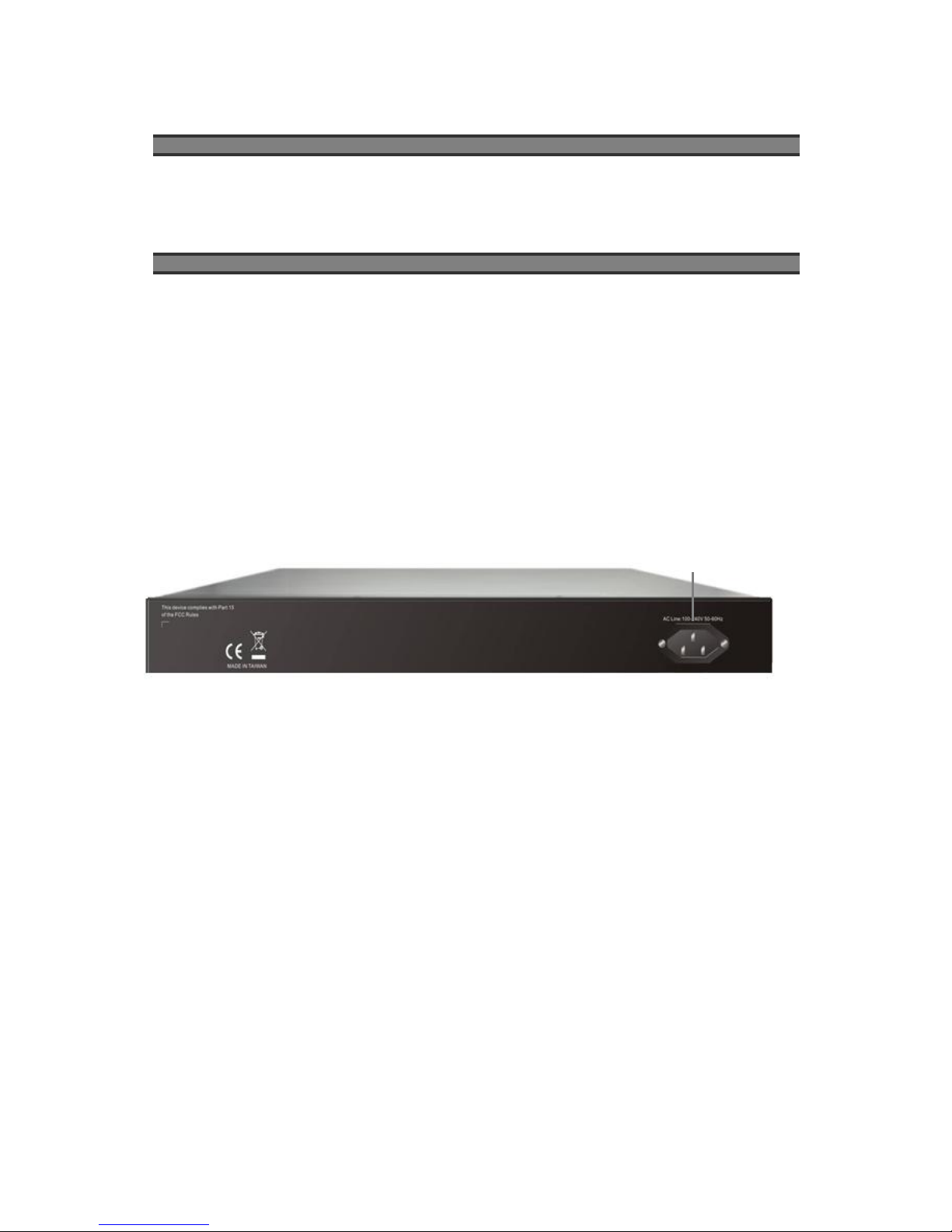
Rear panel of the Switch
Figure 2 Rear panel of the switch
AC Power Socket

3
Chapter 2 Installing The Switch
C
AUTION
:
Circuit devices are sensitive to static electricity, which can
damage their sensitive electronics. Dry weather conditions or walking
across a carpeted floor may cause users to acquire a static electrical
charge.
To protect your device, always:
Touch the metal chassis of your computer to ground the static electrical
charge before you pick up the electronic device.
It is recommended to use a surge arrester for all outdoor devices
Figure 3 Add a surge arrester between the outdoor device and switch
NOTE: The switch is an indoor device; if used with outdoor devices such
as outdoor IP camera or outdoor WiFi APs, users must install a surge
arrester to protect the switch
W
ARNING
:
Tampering, mishandling or improper installation of the device will
void manufacturer’s warranty.
Do not place the switch in outdoor environment.
Before installation, please make sure the input voltage meets the
product’s specified power requirements.
Before importing / exporting configuration file, please make sure the
firmware version is always the same.

4
Package Contents
VX-GPF1626 GbE Management Switch
Four adhesive rubber feet
Mounting Accessory (Optional for 19”Rack Shelf)
Installation Guide
AC Power cord
Console cable
Mounting the Switch in a 19-inch Rack
Step1. Attach the mounting brackets to both sides of the chassis with screws.
Figure 4 Attaching mounting brackets to the switch
Step2. Place the switch on a rack shelf in the rack. Push the switch in until the oval holes in the
brackets align with the mounting holes in the rack posts.
Step3. Attach the mounting brackets to the rack posts with screws.
Figure 5 Attaching mounting brackets to the rack post

5
Mounting the Switch on Desk or Shelf
Step1. Verify that the workbench is sturdy and reliably grounded.
Step2. The rubber feet are included in the accessory kit. Attach the four adhesive rubber feet to the
bottom of the switch.
Figure 6 Attaching the Rubber Feet

6
Connecting the AC Power Cord
Figure 7 Connecting the AC power cord to the AC power receptacle
Step1. Connect one end of the AC power cord to the AC power receptacle on the switch.
Step2. Connect the other end of the AC power cord to the AC power outlet.
Step3. Examine the power LED. If it is ON, the power connection is correct.

7
Installing SFP Modules
You can install or remove a mini-GBIC SFP from a mini-GBIC slot without having to power off the
switch. Use only Manufacture mini-GBIC.
Step1. Insert the module into the switch port.
Step2. Press firmly to ensure that the module fits into the connector.
Figure 8 Installing a SFP Module into a SFP Module Slot
Connecting Console Port
Figure 9 Connecting Console Port
Start a terminal application such as HyperTerminal on the computer. Configure the utility with the
following parameters
Default Baud rate—115,200 bps
Parity—None
Stop bit—1
Data bits—8
Flow control—none
(The default username is “admin” and password is empty.)

8
Chapter 3 Managing Switch Using the Web Interface
Manage the Switch Using Web Browser
After you power up the switch for the first time, you can configure the switch using a web browser. For
more information about managing the switch, see the user interface manual.
Figure 10 Web Interface login page
Step1. Power on the computer and the switch.
Step2. Plug in the power cable.
Step3. Set the IP configuration on your computer.
NOTE:
1. If the switch is using the default factory IP address of 192.168.1.1,
users can choose an IP address for the computer in the range of
192.168.1.1—192.168.1.253 that is not already in use.
2. If the IP address is assigned by a DHCP server, ensure the DHCP
server is running and can be reached from the switch and the
computer. It might be necessary to disconnect and reconnect the
devices for them to discover their new IP addresses from the DHCP
server.
Step4. Enter the username and password (The default username is “admin” and the password should
remain empty) and then click “Login” to login to the switch configuration window.

9
Chapter 4 Troubleshooting
Troubleshooting Chart
The following table lists Issues, Causes, and Action to possible problems.
Table 3 Troubleshooting Chart
Issues
Cause
Action
SYSTEM LED Off
No power is received.
Check the power cord connections for the
switch and the connected device.
Make sure that all cables used are correct
and comply with Ethernet specifications.
Link LED Off
Port connection is not working.
Check the crimp on the connectors.
Ensure that the plug is fully inserted
and locked into the port on both the
switch and the connecting device.
Ensure that the correct cables are
used and comply with Ethernet
specifications.
Check for a defective adapter card,
cable, or port by testing it in an
alternate environment where all units
are functioning.
Slow file transfer
or performance
degradation.
Half- or full-duplex setting on
the switch and the connected
device are not the same.
Ensure that the attached device is set
to auto-negotiate.
Check the system message log.
Device is not
recognized as
part of the
network.
One or more devices are not
properly connected, or cabling
does not meet Ethernet
guidelines.
Verify that the cabling is correct. Ensure
that all connectors are securely connected
to the appropriate ports. Equipment
might have been accidentally
disconnected.

10
Appendix A Technical Specifications
Hardware Specification
Table 4 Hardware Specification
Port Configuration
10M/100M/1G RJ45 Port
24
100M/1G/2.5G RJ45 Port
--
100M/1G/10G RJ45 Port
--
100M/1G SFP Port
--
1G/2.5G SFP Port
--
1G/10G SFP+ Port
--
GbE RJ45/SFP Combo Port
2
Console Port
--
Total Ports
26
PoE Function
IEEE802.3at (PoE+ 30W)
Y
IEEE802.3af (PoE 15.4W)
Y
UPoE(60W)
--
PoE Port
24
Available PoE Power
370W
HW Performance
Switching Bandwidth
52Gbps
Forwarding Performance
38.7Mpps
MAC Address
8K
Jumbo Frames
9216 Bytes
Environmental Specification
Operating Temperature
0°C to 45°C
Operating Humidity
10 to 90% RH
Storage Temperature
-20 to 70°C
Storage Humidity
10 to 90% RH
Mechanical Specification
Dimensions (H) x (W) x (D) mm
44 x 442 x 211
Weight
3.5 Kg
FAN Less
--
Power Source
AC Input
100V-240V
DC Input
--
AC/DC Dual Input
--

11
1000 MBPS Gigabit Ethernet Collision Domain
Table 5 Maximum 1000BASE-T Gigabit Ethernet Cable Length
Cable Type
Maximum Cable Length
Connector
Category 5, 5e or 6 100-ohm UTP
or STP
100.m (328 ft)
RJ-45
Table 6 Maximum 1000BASE-SX Gigabit Fiber Cable Length
Fiber Size
Fiber Bandwidth
Maximum Cable Length
Connector
62.5/125 micron
multimode fiber
160 MHz/km
200 MHz/km
220 m (722 ft)
275 m (902 ft)
LC
LC
50/125 micron
multimode fiber
400 MHz/km
500 MHz/km
500 m (1641 ft)
550 m (1805 ft)
LC
LC
Table 7 Maximum 1000BASE-LX/LHX/XD/ZX Gigabit Fiber Cable Length
Fiber Size
Fiber Bandwidth
Maximum Cable Length
Connector
9/125 micron singlemode fiber 1310nm
N/A
10km (6.2 miles)
LC
9/125 micron singlemode fiber 1550nm
N/A
30km (18.64 miles)
50km (31.06 miles)
LC
LC
Table 8 Maximum 1000BASE-LX Single Fiber Gigabit Fiber Cable Length
Fiber Size
Fiber Bandwidth
Maximum Cable Length
Connector
Single-mode
TX-1310nm
RX-1550nm
N/A
20km (12.42miles)
BIDI
LC
Single-mode
TX-1550nm
RX-1310nm
N/A
20km (12.42miles)
BIDI
LC
 Loading...