

VERSATEC V036W, V080W, V060W, V120W Installation Manual

Water-to-Water Heat Pumps
3, 5, 7, 10 Ton Capacity•
Installation Information
Water Piping Connections
Electrical Connections
Startup Procedures
Preventive Maintenance
Versatec Installation Manual
IM1355 11/06
WFI
VERSATEC WATER-TO-WATER INSTALLATION MANUAL
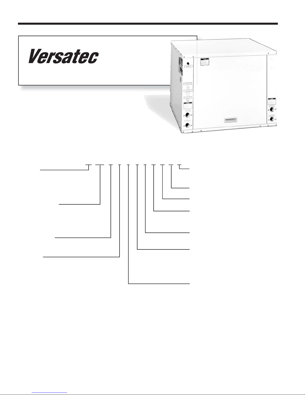
Model Nomenclature
Family
VL = Versatec (Low Temp)
50° - 110° F EST
VX = Versatec (Ext. Range)
30° - 110° F EST
Unit Capacity
036 = MBTUH
060 = MBTUH
080 = MBTUH
120 = MBTUH
Model Type
W = Water-to-Water
Voltage
0 = 208-230/60/1 Commercial
2 = 265/60/1 Commercial
3 = 208-230/60/3 Commercial
4 = 460/60/3 Commercial
5 = 575/60/3 Commercial
8 = 380/60/3 Commercial
036 W 4 C C 0 A S S A
VL
Vintage
A = 036 (& 575 Volt 060)
B = All Others
Non-Standard Options Detail
Non-Standard Options
Sound Kit
A = None
B = Blanket
Cabinet Finish
0 = Painted Cabinet
Load Coax Options
C = Copper
D = Vented
(Potable Water 036 Model Only)
N = Cupronickel
Source Coax Options
C = Copper
N = Cupronickel
2

VERSATEC WATER-TO-WATER INSTALLATION MANUAL
T able of Contents
General Installation Information 4-5
Water Loop (Boiler/Tower) Systems 6
Open Loop Systems 7
Earth-Coupled Systems 7
Physical Data 8
Electrical 8
Wiring Schematics 9-11
Startup 12
Operating Specifi cations 13
Pressure Drop Data 14
Troubleshooting 15
Preventive Maintenance 15
Replacement Procedures 15
3
VERSATEC WATER-TO-WATER INSTALLATION MANUAL
General Installation Information
Safety Considerations
Installation and servicing of heating and air conditioning equipment can be hazardous due to system pressure and electrical components. Only trained and qualifi ed service personnel should install, repair or service heating and air conditioning
equipment. When working on heating and air conditioning equipment, observe precautions in the literature, tags and labels
attached to the unit and other safety precautions that may apply.
Follow all safety codes. Wear safety glasses and work gloves. Use quenching cloth for brazing operations. Have fi re
extinguisher available for all brazing operations.
Notes: Before installing, check voltage of unit(s) to ensure proper voltage.
WARNING:
the unit. Turn off accessory heater power switch if applicable. Electrical shock could cause serious personal injury.
Before performing service or maintenance operations on the system, turn off main power switches to
Moving and Storage
Move units in the normal “UP” orientation as indicated by the arrows on each carton. Do not stack more than three (3)
units in total height. When the equipment is received, all items should be carefully checked against the bill of lading to be
sure all crates and cartons have been received. Examine units for shipping damage, removing the units from the cartons if
necessary. Units in question should also be internally inspected. If any damage is noted, the carrier should make the proper
notation on the delivery receipt, acknowledging the damage.
Unit Location
Locate the unit in an indoor area that allows easy removal of the access panels and has enough space for service
personnel to perform maintenance or repair. Provide suffi cient room to make water and electrical connections. If the unit is
located in a confi ned space such as a closet, provisions must be made for unit servicing. Units may be stacked vertically in
small mechanical rooms. These units are not approved for outdoor installation and, therefore, must be installed inside the
structure being conditioned.
CAUTION: Do not locate in areas subject to freezing.
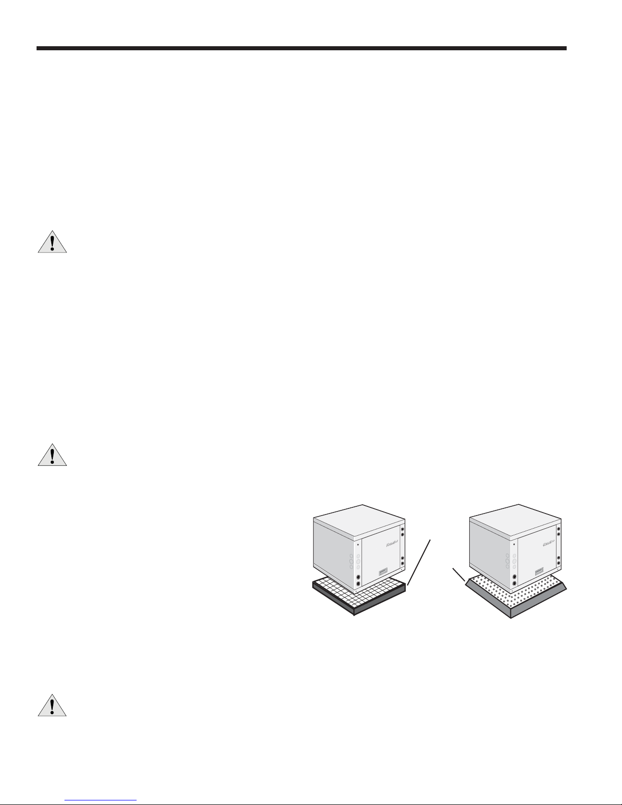
Mounting Units
Units should be mounted level on a vibration absorbing pad slightly larger than the base to provide isolation
between the unit and the fl oor. It is not necessary to anchor
the unit to the fl oor. Allow access to front access panel for
servicing compressor.
Figure 1: Unit Mounting
Vibration
Absorbing
Mesh
Air
Pad
Hanging Units
Versatec water-to-water units can be suspended from
the ceiling using 3/8'' threaded rods. The rods are usually attached to the unit by optional hanger bracket kits
(99S500A01). Lay out the threaded rods per the dimensions and assemble the hangers to the unit (see Figure 2). Securely
tighten the brackets to the unit using the weld-nuts located on the underside of the bottom panel. When attaching the rods to
the bracket, a double nut is required since vibration could loosen a single nut. Use the bolts provided in the kit to attach the
brackets. The use of longer bolts could damage internal parts.
CAUTION: Do not use rods smaller than 3/8'' diameter since they may not be strong enough to support the unit.
The rods must be securely anchored to the structure.
4
VERSATEC WATER-TO-WATER INSTALLATION MANUAL
General Installation Information (cont.)
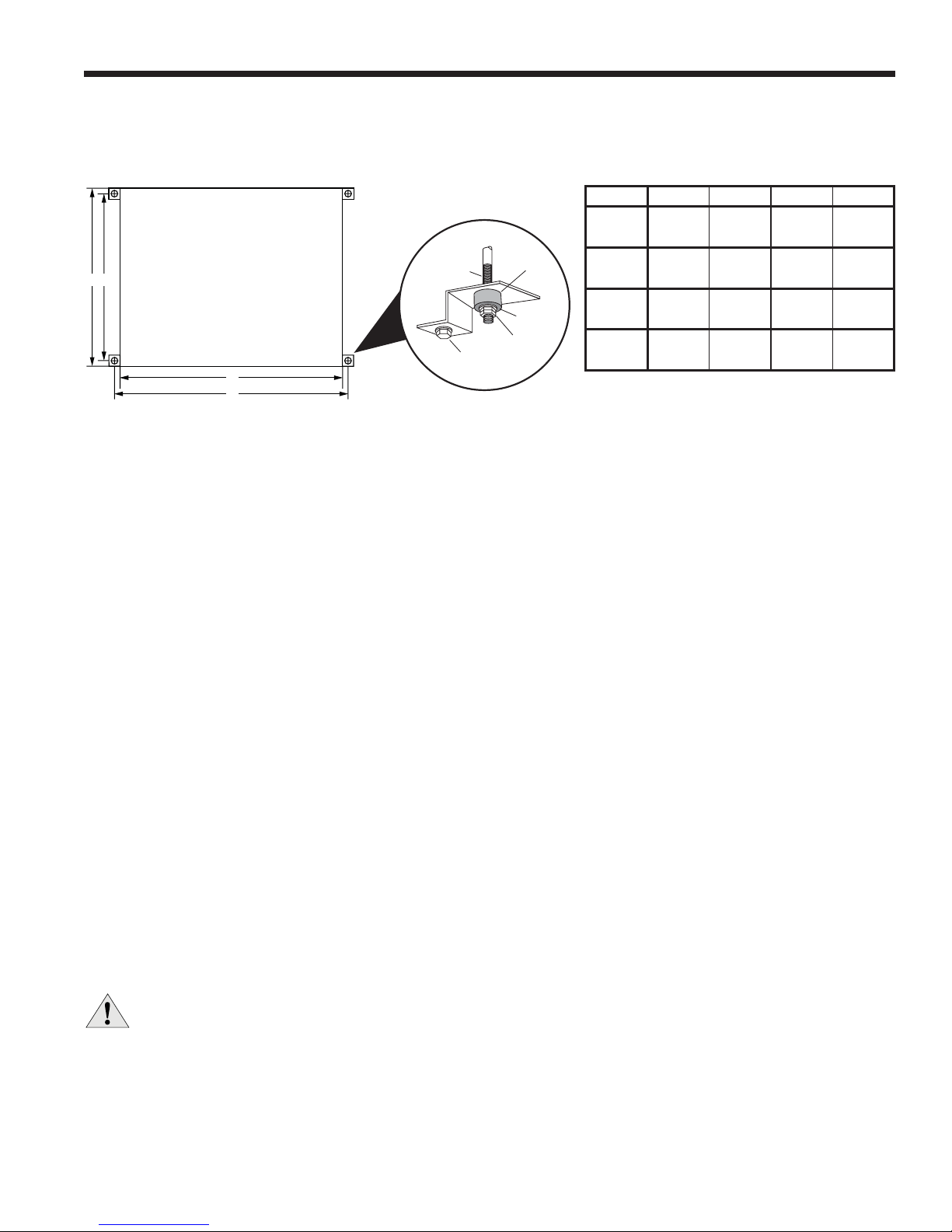
Figure 2: Hanger Locations and Assembly
MODEL A B C D
V036W
3/8”Threaded
C
A
D
B
Rod (by others)
Bolt and
Lockwasher
Washer
(by others)
Hex Nuts
(by others)
Vibrator
Isolator
V060W
V080W
V120W
Notes: Dimensions are inches [cm]. Rev. 11/23/05
General Piping
Each unit is equipped with FPT fi ttings for the water supply and return lines. For making the water connections to the
unit, a Tefl on tape thread sealant is recommended to minimize internal fouling of the piping. Do not overtighten connections.
The water lines should be routed so as not to interfere with access to the unit. The use of a short length of high pressure
hose with a swivel type fi tting may simplify the connections and prevent vibration.
Before fi nal connection to the unit, the supply and return hose kits must be connected, and the system fl ushed to remove
dirt, piping chips and other foreign material. Normally, a combination balancing and close-off (ball) valve is installed at the
return, and a rated gate or ball valve is installed at the supply. The return valve can be adjusted to obtain the proper water
fl ow. The valves allow the unit to be removed for servicing.
The proper water fl ow must be delivered to each unit whenever the unit heats or cools. To assure proper fl ow, the use of
pressure/temperature ports is recommended to determine the fl ow rate. These ports should be located adjacent to the sup-
ply and return connections on the unit.
The proper fl ow rate cannot be accurately set without measuring the water pressure drop through the refrigerant-to-water
heat exchanger (See Pressure Drop Table, page 14 for water fl ow and pressure drop information). Normally about 3 GPM
fl ow rate per ton of cooling capacity (2.25 GPM per ton minimum) is needed.
Both source as well as load fl uid piping must be at least as large as the unit connections on the heat pump (larger on
long runs). Unit may be furnished with either a copper or optional cupronickel coil on either source or load coaxial heat
exchangers. Copper is adequate for closed loop systems and ground water that is not high in mineral content. In condtions
anticipating moderate scale formation or in brackish water, a cupronickel heat exchanger is recommended.
29.5 32.6 30.5 30.5
[74.9] [83.1] [77.5] [77.5]
29.5 32.6 30.5 30.5
[74.9] [83.1] [77.5] [77.5]
28.75 39.9 30.0 37.75
[73.0] [101.3] [76.2] [95.9]
28.75 39.9 30.0 37.75
[73.0] [101.3] [76.2] [95.9]
Notes: Cupronickel should always be used when chlorinated water is used as the source or load liquid.
For process water applications, it is recommended that a secondary load heat exchanger be installed to prevent corrosion to the unit's primary coaxial coil. In situations where scaling could be heavy or where biological growth such as iron
bacteria will be present, a closed loop system is recommended. Over a period of time, ground water unit heat exchanger
coils may lose heat exchange capability due to a buildup of mineral deposits. These can be cleaned only by a qualifi ed ser-
vice mechanic as special pumping equipment and solutions are required.
Never use fl exible hoses of a smaller inside diameter than that of the water connection on the unit and limit hose length
to 10 ft. per connection. Check carefully for water leaks.
CAUTION:
Water piping exposed to outside temperature may be subject to freezing.
Potable Water Systems
An optional domestic water coil is available on the 036 model to provide primary generation of domestic hot water. The
coaxial heat exchanger provides double-wall construction and is vented to allow installation in potable water systems.
5
 Loading...