


®
VersaPulse® Select™
SERVICE MANUAL
This service manual is to be used in conjunction with the operator manual for the product. The
operator manual contains important information regarding instrument description, location of
controls, specifications, and normal operating procedures.
®
DANGER
VISIBLE AND INVISIBLE LASER RADIATION.
AVOID EYE OR SKIN EXPOSURE TO
DIRECT OR SCATTERED RADIATION.
HOLMIUM:YAG LASER: 2.1 MICROMETERS
MAX OUTPUT 5 JOULES 250 µs PULSE
Nd:YAG LASER: 1.06 MICROMETERS
MAX. OUTPUT 2 JOULE 350 µs PULSE
DIODE LASER: 650 NANOMETERS
MAX OUTPUT 5 MILLIWATTS
CLASS IV LASER PRODUCT
Santa Clara, CA 95051
DANGER
®
2400 Condensa Street
(408) 764-3000
VISIBLE AND INVISIBLE LASER RADIATION.
AVOID EYE OR SKIN EXPOSURE TO
DIRECT OR SCATTERED RADIATION.
HOLMIUM:YAG LASER: 2.1 MICROMETERS
MAX OUTPUT 5 JOULES 250 µs PULSE
DIODE LASER: 650 NANOM ETERS
MAX OUTPUT 5 MILLIWATTS
CLASS IV LA SER PRODUCT
®
0621-499-01
DEC. 95

®
®
This manual is copyrighted with all rights reserved. Under the copyright laws, this manual cannot be copied
in whole or part without the express written permission of Coherent, Inc. Permitted copies must carry the
same proprietary and copyright notices as were affixed to the original.
Please note that while every effort has been made to ensure that the data given is accurate, the information,
figures, illustrations, tables, specifications, and schematics are subject to change without notice.
Coherent and the Coherent Logo are registered trademarks of Coherent, Inc.
Please direct all inquiries about this manual to:
Coherent, Inc.
Technical Support B-35
2400 Condensa Street
Santa Clara, CA 95051
(408) 764-3638
© Coherent, Inc 01/94, 07/94, 08/95, 10/95, 12/95
0621-499-01

®
DISCLAIMER
Coherent service manuals are written specifically for use by Coherent service engineers who have received
formal training in the servicing of Coherent equipment, and by customers who have taken and passed a
Coherent certification service training course for the equipment being serviced. Information on certification
service training courses offered to customers can be obtained by contacting the Technical Training Coordinator at 800-367-7899.
Coherent does not accept responsibility for personal injury or property damage resulting from the servicing
of Coherent equipment by its customers or by third parties, except where such injury or property damage is a
direct result of Coherent's negligence. Customers, by accepting the service manual, agree to indemnify
Coherent against any claims alleging personal injury or property damage resulting from the servicing of
Coherent equipment by the customer or by third parties, except where such injury or property damage is a
direct result of Coherent's negligence. These limitations include situations where Coherent personnel are
advising customers on the repair of Coherent equipment over the telephone.
The servicing of Coherent equipment by persons who have not passed a current Coherent certification
service training course for that equipment will void Coherent's product warranty.
®
VersaPulse Select Service Manual Disclaimer 0621-499-01 12/95

®
®
REVISION INFORMATION
This is the DEC '95 release of the Versapulse Select Service Manual. Contact Coherent Medical Group Technical Support to determine if this is the most current release of this service manual.
Each page of this manual has a MM/YY date at the bottom. This indicates the release date for the individual
page. Note that when the manual is updated, not all of the pages are necessarily updated, so some pages
may have a MM/YY earlier than the release date for the manual (the release date for the manual is the MM/
YY that appears on the cover and in the first sentence of this revision information page). The following list
provides a complete list of the release date information, by section, for this release of the service manual.
Cover page, copyright page, disclaimer page, this page, table of contents page or pages are all dated with the
release date of the manual (12/95).
SECTION 1 Pages 1-1, 01/94
Pages 1-2, 12/95
SECTION 2 Pages 2-1,4,6 12/95. All other pages 03/94.
SECTION 3 Pages 3-1 thru 3-10 12/95. All other pages, 03/94.
SECTION 4 Pages 4-4 Thru 4-17, 4-22 Thru 4-30, 12/95.
All other pages, 01/94
SECTION 5 All pages, 12/95
SECTION 6 All pages, 12/95
SECTION 7 FSB's released for this service manual are listed in the Versapulse Select FSB
Index. Each time an FSB for this manual is released or updated the Index is
also updated and distributed with the FSB. The current Index is placed
behind the single sheet that makes up Section 7, and the FSB's are placed in
order behind the Index. Contact Coherent Medical Group Technical Support
for the date of the most current FSB Index.
SECTION 8 Page 8-1,12, 10/95
Pages 8-2 thru 8-11, 8-13 thru 8-18, 01/94
Pages 8-19 thru 8-30, 08/95
.
VersaPulse Select Service Manual Revision Information 0621-499-01 12/95

®
Table Of Contents
DISCLAIMER .................................................................................................................................................. 3
REVISION INFORMATION ........................................................................................................................ 4
1.0 GENERAL INFORMATION ............................................................................................................... 1
1.1 USE OF THIS MANUAL .......................................................................................................................1
1.2 CONVENTIONS USED IN THIS MANUAL.......................................................................................1
1.3 SERIAL NUMBERS ............................................................................................................................... 2
2.0 INSTALLATION ....................................................................................................................................1
2.1 INSTALLATION INSTRUCTIONS......................................................................................................1
3.0 CALIBRATION & ADJUSTMENT ....................................................................................................1
3.1 OVERVIEW............................................................................................................................................ 1
3.1.1 Safety Precautions ..................................................................................................................................1
3.2 System Check Out .................................................................................................................................. 2
3.3 Energy Monitor and Automatic Laser Calibration..............................................................................5
3.4.1 Making Test Burns .................................................................................................................................. 7
3.4.2 Adjusting the YAG Channel Optics .......................................................................................................7
3.4.3 YAG Channel Check Out and Adjustment Procedure......................................................................... 8
3.5 AIMING BEAM ADJUSTMENT ........................................................................................................10
3.6 PERIODIC MAINTENANCE REQUIREMENTS............................................................................ 13
4.0 THEORY OF OPERATION.................................................................................................................. 1
4.1 INTRODUCTION ...................................................................................................................................1
4.1.1 Operational Overview ............................................................................................................................. 1
4.1.2 Functional Overview ...............................................................................................................................2
4.2 POWER SWITCHING, CONDITIONING, DISTRIBUTION .......................................................... 5
4.2.1 Input Power..............................................................................................................................................5
4.2.2 Circuit Breaker on, Keyswitch off .........................................................................................................5
4.2.3 Turn on ..................................................................................................................................................... 5
4.2.4 Shutdown..................................................................................................................................................6
4.2.5 Low Voltage Power Supplies................................................................................................................... 6
4.3 COOLING................................................................................................................................................7
4.4 CONTROL ELECTRONICS ................................................................................................................. 9
4.4.1 Overview...................................................................................................................................................9
4.4.2 Main Processor ...................................................................................................................................... 10
4.4.3 Shutter / Footswitch / Remote Interlock Circuits............................................................................... 11
4.4.4 Servo Motor Control Circuit ................................................................................................................ 13
4.4.5 HVPS & PFN Control Circuits ............................................................................................................14
4.4.6 Energy Monitor Circuits.......................................................................................................................17
4.4.7 Touch Screen & Remote Control Circuits ........................................................................................... 18
4.4.8 Aiming Diode Laser Circuit..................................................................................................................20
4.4.9 Fiber and Blast Shield Position Sense Circuits ...................................................................................21
4.4.10 Service Attenuator Circuit .................................................................................................................. 22
4.4.11 Coolant Temperature and Conductivity Monitoring Circuits.........................................................23
4.4.12 Low Energy Attenuator Circuit ......................................................................................................... 24
4.4.13 DC Power Supply Voltage Monitoring Circuits.................................................................................24
4.4.14 Safety Processor....................................................................................................................................25
4.5 FLASH LAMP POWER CIRCUITS.................................................................................................. 27
4.6 OPTICS .................................................................................................................................................27
4.7 SOFTWARE.......................................................................................................................................... 29
®

®
®
5.0 TROUBLESHOOTING ........................................................................................................................ 1
5.1 OVERVIEW............................................................................................................................................. 1
5.1.1 Service Philosophy..................................................................................................................................1
5.1.2 Safety Precautions ..................................................................................................................................2
5.2 INTERIOR ACCESS & PART LOCATIONS.....................................................................................3
5.3 SERVICE MODE ................................................................................................................................. 12
5.4 FAULT ISOLATION............................................................................................................................14
5.4.1 TURN-ON AND SHUTDOWN FAULT ISOLATION ...................................................................... 15
5.4.2 "NO FAULT CODE REPORTED" FAULT ISOLATION ...............................................................15
5.4.3 "FAULT CODE REPORTED" FAULT ISOLATION .....................................................................15
6.0 SELECTED PARTS ................................................................................................................................ 1
8.0 SCHEMATICS AND DRAWINGS .................................................................................................... 1

®
1.0 GENERAL INFORMATION
1.1 USE OF THIS MANUAL
This manual contains service instructions for the Coherent VersaPulse Select series of Holmium:YAG surgical
lasers. The content of this manual is intended solely for use by Coherent Medical Group Field Service Engineers
and Coherent trained and certified customer technicians. Coherent, Inc. can not be responsible for service or
repairs attempted by uncertified persons, and the use of this manual by such persons is prohibited.
This manual is to be in conjunction with the Coherent Operator Manual for the VersaPulse Select. The operator
manual contains important information regarding instrument description, location of controls, specifications,
and normal operating procedures.
®
As necessary, Coherent Medical Group Service Technical Support releases Field Service Bulletins for the
Versapulse Select series. These bulletins supplement the information in this manual. As they are released, the
bulletins become a part of this manual (Section 7).
1.2 CONVENTIONS USED IN THIS MANUAL
Within the text, logic signals that are active low ("notted") will appear inside of slash marks, as illustrated below.
/BRHOK/
These signals are "active", or true, when the logic level is low. When the logic signal /BRHOK/ is low, the BRH
loop is "OK" (complete). When the logic signal /BRHOK/ is high, the BRH loop is not OK (open).
In most of the schematic diagrams such signals are indicated by the more usual solid line above the signal name,
as illustrated below.
BRHOK
The schematics in this manual do not include individual numbers for the logic elements or operational amplifiers
within a single component. For example, U1 below contains two operational amplifiers. The top op amp would
be referred to as U1-1 ( its output is pin 1), and the other would be referred to as U1-7.
VersaPulse Select Service Manual
0621-499-01 01/94
GENERAL INFORMATION
1-1

®
®
2
U1
3
6
U1
5
1.3 SERIAL NUMBERS
Serial numbers for the Versapulse Select are in the format,
MYPHWVXXXX
1
7
where M is the month produced
Y is the last digit of the year produced
P is a number indicating maximum system power
H is the number of laser heads installed (1, 2, 3, or 4)
W is a number indicating the mix of rods installed
V is a number indicating power supply configuration
XXXX is the number of the laser built
W: 1= Holmium only
2= Erbium only
3= Nd:Yag only
5= Nd/Ho combo
(a is January, b is February, etc..)
(4 is 1994., etc..)
(6=60w, 4=45w, 3=30w)
(See Below)
(1= 208VAC single phase)
(0001, 0002, etc..)
GENERAL INFORMATION
1-2
VersaPulse Select Service Manual
0621-499-01 12/95

®
2.0 INSTALLATION
2.1 INSTALLATION INSTRUCTIONS
These installation instructions are provided for use by Coherent Service Engineers who have completed
certification service training on the VersaPulse Select. Installation by untrained persons is a potential hazard
to the person or persons doing the installation, others present, and to the equipment itself. In addition,
improper installation is a potential hazard to the user, persons present during use, and patient.
Perform the following steps to install a VersaPulse Select system.
®
1. Check for proper site set up. This includes proper AC service and adequate space for the console.
AC power configuration: The VersaPulse Select requires 220 VAC ±10%, 50/60 Hz, 30 amp single
phase electrical service. The power cord is a 26 foot cable with 3 conductors. A terminal board
behind the right side cover allows for tapping of the isolation transformer to the setting closest to the
incoming electrical service. The system can be hard wired to electrical service or installed to electrical
service with a plug and receptacle. The plug and receptacle are shipped in the site preparation kit.
Console dimensions and weight: The console measures 39" l x 18" w x39" h. It weighs approximately
325 lbs. A minimum of 18" of air space is required around the unit to provide adequate cooling air
circulation.
The system requires approximately 2.5 gallons of deionized water for its closed loop cooling system.
The coolant must be added as described in this procedure.
Complete specifications for the VersaPulse Select are included in the VersaPulse Select Operator
Manual. Contact Technical Support in Palo Alto, CA, if there are any questions concerning site
preparation.
2.) Check the crate/carton for any shipping damage.
VersaPulse Select Service Manual
0621-499-01 12/95
INSTALLATION
2-1

®
®
CARDBOARD TOP COVER
STRAP
WOODEN RAMPS
CARDBOARD SIDE COVER
STRAP
FOAM
Accessories
Removable
wooden ramp (2)
INSTALLATION
2-2
Front lifting bolts
(2, 3/4ths)
LIFTING BAR (2)
As the bolts turn, the lifting bar is raised or lowered. The system
ships with the lifting bar up. The bar must be lowered and removed,
then the system is rolled down the wooden ramps to remve it from
the crate base.
FIGURE 2.1 SHIPPING CRATE
WOODEN
BASE
Rear lifting bolts
(2, 5/8ths)
VersaPulse Select Service Manual
0621-499-01 12/95
03/94

The shipper is responsible for any damage to the system in shipment. If the crate/carton appears to
be damaged, report the damage to the customer and shipper.
3.) Remove the console and accessories from the crate.
Refer to drawing 2-1. Remove the straps, remove the top cover, remove the side cover, remove the
protective foam, remove the accessories box, then locate and remove the two wooden ramps stored in
the base. Lower the lift plates (2) by turning the bolt at each end of each lift plate (5/8" and 3/4"
bolts). Loosen the bolts all the way, then remove the bolts and lift plate. Remove the front fence from
the base by removing the four wing nuts that secure it to the base. Install the ramps onto the base,
then roll the unit down the ramps.
4.) Move the system to its installation location.
The VersaPulse Select rolls best when pushed from the front handles. The front wheels swivel, the
rears wheels do not.
6.) Open/remove covers and do a visual inspection of the interior.
®
®
Refer to Section 5 for information on removing the covers. Open the front cover, then remove the top
and two side covers. Inspect the interior carefully for loose or broken electrical connections, loose or
broken plumbing connections, or any indication of shipping damage.
7.) Set up for site AC.
Measure the voltage of the site electrical service at the point where the VersaPulse Select will be
connected. The three connections include an earth ground and two hot mains. Measure line voltage
across the two hot mains. Mains voltage must be between 200 and 240 VAC, 50/60 Hz. Confirm that
the circuit is rated for 30 amps.
The isolation transformer has two secondaries: one operates the turn-on circuitry and the other
provides AC to the low voltage power supply, display power supply, fan and pump. These
secondary loads (not the turn-on circuitry) are rated for 220 VAC supply input. The isolation
transformer is tapped to allow a range of AC line inputs ( 200 to 240 VAC) to be stepped up or down
to result in a secondary voltage at or near 220 VAC to these secondary loads. The various taps on the
isolation transformer are wired out to terminal board TB1 on the right side on the system. The
tapping is done by changing the connections at the terminal board.
POWER CORD
TB1
MAINS TO CIRCUIT BREAKER
VersaPulse Select Service Manual
0621-499-01 12/95
03/94
MAINS (from F1)
MAINS ( from F2)
120
120
100
100
ISOLATION
XFORMER
(primary)
EARTH GROUND TO
GROUNDING STUD
FIGURE 2-2 TB1 TAPPING
INSTALLATION
2-3

®
8.) Connect to AC service.
CAUTION: Once connected to site electrical service lethal voltages are present inside the unit. The
AC power is present at the circuit breaker, main contactor and isolation transformer. In addition, the
isolation transformer secondary outputs are hot. Review and understand the safety subtopic in
Section 5 before proceeding.
The system can be hard wired to electrical service, but is more typically connected by a plug to an
electrical outlet.
If the system is to be hard wired, the customer must provide an electrician to wire the cord end into
the electrical service outlet.
If the system is to be plugged into an electrical receptacle, the appropriate receptacle should already
be installed by the customer's electrician. The installing engineer connects the plug to the end of the
VersaPulse Select electrical cable.
9.) Add coolant.
®
Add coolant (deionized water) to the fill reservoir. The coolant will drain out of the fill reservoir and
into the main reservoir. The system uses approximately 2.5 gallons of coolant. Most of the coolant
can be added at this time - until the fill reservoir level stays up. The system coolant level will be
"topped off" after the system is turned on (in a later step).
9.) Initial power application.
CAUTION: Once the circuit breaker is turned on lethal voltages are present throughout the system.
With the side covers still removed, turn on the electrical service and turn on the circuit breaker on the
VersaPulse Select. Wait a few minutes, observing for any indication of failure of mains or turn-on
components.
10.) Initial turn on.
CAUTION:
• The system will fire during the turn-on sequence if SW3 (Autocal) on the CPU PCB is up
and the BRH plug is installed. Only those persons required should be present during this
portion of the installation
• The cooling fan blades are not covered. The fan is located on top of the heat exchanger. It
operates whenever the system is turned on. Keep tools, system parts and body parts clear of
the fan blades.
Turn the keyswitch to the START position, then release it to the ON position. The system will go
through its start up sequence. Observe for normal start up, and for any indication of leaks in the
cooling system.
INSTALLATION
2-4
VersaPulse Select Service Manual
0621-499-01 12/95

11.) Add coolant.
With the system turned on, top off the fill reservoir. Cycle the machine off and on several times,
adding coolant as necessary until the fill reservoir level stays up to approximately half full as the
system runs.
12.) Operational and Safety Checkout.
Attach a test fiber, remote interlock plug, and footswitch, then check system operation as follows:
a.) Footswitch, remote control (if included) and remote interlock plugs connect properly to jacks.
b.) Fiber attaches to the fiber port.
c.) Touch screen display matrix is operating properly.
d.) Touch screen inputs are functional.
®
®
e.) Remote control (if installed) display and input buttons are functional.
f.) Aiming beam responds to off, low, medium, and high settings.
CAUTION: The remaining operational tests include firing the system and attempts to fire the system
with one disabling condition. Select a low power setting and direct the test fiber output into a
calibrated power meter.
g.) Fire into the meter for several seconds, noting the power reading on the meter.
i.) Confirm that the total energy display value has incremented, then confirm that the value clears
back to zero when RESET is touched.
j.) Disconnect the footswitch and confirm that the "ATTACH FOOTSWITCH" message appears on the
display.
k.) Reconnect the footswitch, then disconnect the fiber and confirm that an "ATTACH FIBER"
message appears on the display. Depress the footswitch and confirm the system will not fire.
l.) Reconnect the fiber, then disconnect the remote interlock plug and confirm the " REMOTE
INTERLOCK" message appears on the display.
m.) Reconnect the remote interlock plug, then go to STANDBY. Depress the footswitch and confirm
the system will not fire.
n.) Pull the blast shield out, then confirm the "REPLACE BLAST SHIELD" message appears on the
display. Depress the footswitch and confirm the system will not fire.
o.) Reinsert the blast shield.
VersaPulse Select Service Manual
0621-499-01 12/95
03/94
INSTALLATION
2-5

®
®
13.) Confirm the power calibration.
Connect a good test fiber onto the fiber port and direct the fiber output towards the head of your
calibrated power meter, then, for each operating point, fire the system into the meter, confirming that
displayed power remains within ± 10% of the power indicated on the meter (typically, the power
calibration will be much more accurate than ±10%). If the power calibration is not better than ±10% at
all operating points, refer to Section 3 for instructions on system calibration.
14.) Check the fiber focus using a test fiber.
Two test fibers are shipped with the system. Check the fiber focus as described in Section 3, topic 3.2,
step 3.
15.) Replace all covers and prepare the system for demonstration to the customer.
16.) Demonstrate the system installation to the customer.
17.) (for U.S. Field Service) Fill out and mail the "self mailer" installation quality audit report.
INSTALLATION
2-6
VersaPulse Select Service Manual
0621-499-01 12/95

®
3.0 CALIBRATION & ADJUSTMENT
3.1 OVERVIEW
This section includes a System Checkout Procedure, Energy Monitor Calibration Procedure, a YAG Channel
Adjustment Procedure and an Aiming Beam Adjustment Procedure. The procedures assume the reader has
successfully completed a Coherent service training course on the Versapulse Select series.
The System Check Out, Topic 3.2, is an operational check of the system. It confirms that the system turns on
properly, responds properly to operator inputs, provides the full range of pulse energies and pulse rates, delivers
average power within ±10% of the displayed average power, delivers the multiplexed YAG beam into the center
on an attached fiber, and provides an adjustable aiming beam through the fiber. It also checks system coolant level
and consumables (i.e., air filter, DI filter and particulate filter).
®
The Energy Monitor Calibration Procedure, Topic 3.3, calibrates the voltage output of the three energy monitor
circuits to the field service engineer's calibrated power meter.
The YAG Channel Adjustment Procedure, Topic 3.4, is done when the System Check Out Procedure indicates
a problem with one or more of the YAG channels. It provides adjustment procedures for the channel cavities and
relay optics.
Aiming Beam Adjustment, Topic 3.5, provides information on adjusting the aiming beam optics to get the aiming
beam out through the fiber. See Section 6 for required tools.
3.1.1 Safety Precautions
Lethal voltages and laser emission are the primary dangers to the servicing engineer. In addition to the general
safety precautions which always apply when working on electronics and lasers, the servicing engineer must be
aware of the following specific precautions:
Only Coherent certified VersaPulse Select Service Engineers should attempt any service on this
system.
Even with the keyswitch and the breaker in the "OFF" position there are potentially lethal voltages
present inside the console. Always disconnect the main electrical service before working on the
console.
Versapulse Select Service Manual
0621-499-01 03/94
12/95
CAL & ADJUST
3-1

®
®
Storage capacitors inside the system are capable of holding a lethal charge, even after power has
been removed from the unit. A charge level indicator bulb located on the PFN PCB mounted across
the top of the main storage capacitor flashes at a rate proportional to the level of charge on the main
charging capacitor. Do not rely on this indicator to determine that the main charging capacitor has
been discharged. Before contacting the main charging capacitor, disconnect the system from primary
power and use a shorting probe to discharge the capacitor to ground.
Do not touch the YAG Cavity Module when the system is on - IT IS A SHOCK HAZARD. The
YAG Cavity Module is electrically isolated from the chassis and can be at a voltage potential much
higher than ground.
Whenever the footswitch is pressed a single pulse is fired immediately, before the shutter opens,
to dump any charge remaining on the charge capacitor. The laser cavity that fires is the one directly
opposite the one that the servo mirror is pointing towards. The energy is dependent upon how much
charge remains on the capacitor. Since the relay mirror is not directed towards the channel, the beam
will be directed away from the first turning mirror (usually towards the mounting screws for the
plano mirrors on the OC wall.
The Ho:YAG, Er:YAG and Nd:YAG laser light is invisible to the human eye. Because the YAG
laser energy can not be seen, there is no visible indication of the primary or reflected beam. Eye
protection that attenuates the Ho:YAG, Nd:YAG and Er:YAG wavelengths to a safe level must be
worn by all persons in the area of the laser system, whenever the laser is being serviced.
The YAG laser light and its reflections are potential burn hazards and can ignite flammable
materials. Use extreme caution when operating the system with covers opened or removed. The
covers contain the beam and reflections safely within the console. Only those persons required
should be present during servicing, and eye protection that safely attenuates the Ho:YAG, Nd:YAG
and Er:YAG wavelengths must be worn by all present.
The Ho:YAG, Er:YAG and Nd:YAG laser light and its reflections are potential hazards to the eye.
Use extreme caution when operating the system with the covers opened or removed. The covers
contain the beam and reflections safely within the console. Only those persons required should be
present during servicing and eye protection that safely attenuates the Ho:YAG, Er:YAG and Nd:YAG
wavelengths should be worn by all those present.
3.2 SYSTEM CHECK OUT
This system check out confirms that the laser is functioning properly.
1.) Open the front door and defeat the door interlock, then turn the system on and allow it to go through
autocalibration. After autocalibration is completed, place the system in service mode.
If the system fails to pass autocalibration, there is something wrong; continue on to step 2 to gather
more information about why the system failed autocalibration.
CAL & ADJUST
3-2
VersaPulse Select Service Manual
0621-499-01 03/94
12/95

2. Check rod calibration values.
Go to the second service screen and note the cap voltage values displayed for each of the four
channels at minimum (low point) and maximum (high point).
The HVPS maximum output is 1500 VDC, so each rod must be capable of making its
maximum pulse energy (high point) at less than 1500 VDC. Typical values at high point are
from 1280 to the low 1400's. Typical voltages for low point are in the 700 to 900 VDC range.
For Nd:YAG the typical values at high point are from 500 to 800 VDC, and typical low point
values are from 200 to 400 VDC.
As the rod temperature increases (during use), its output will tend to drop off for a given cap
voltage. The software compensates for this effect, so as the rod temperature increases, it is
normal to see the cap charge voltage required at a particular pulse energy increase. Since the
system goes through its autocalibration at turn on, when the rods tend to be cooler, the cap
charge voltages found during autocal will tend to be lower than those that might be required
during sustained, high duty cycle operation. Thus, a channel with a cap charge voltage in the
mid to high 1400's @ 2.8 Joules at turn on may require a cap charge voltage higher than the
HVPS can provide to make 2.8 Joules during operation.
®
®
If the system has failed to complete autocalibration or channel performance appears poor, perform
the YAG Channel Adjustments (Topic 3.4).
3. Inspect debris shield and clean/replace as required.
4. Check the power supply voltages, coolant temperature and coolant conductivity.
5. Check the fiber focus using a test fiber.
If the system passes autocalibration and channel performance appears normal (service screen min/
max cap charge values are good), check for proper alignment of the beam into the fiber. This is done
using a special test fiber (0621-675-01). The fiber proximal end is coated with a red ink (Berol 8800
red marker) that records an impression of the YAG beam footprint where it enters the end of the
fiber. The laser is fired into the test fiber, then the fiber end is examined using a hand held 100X
microscope. A good alignment will result in a "concentric" footprint, i.e., the footprint will be
approximately centered in the fiber core and be well away from the cladding that surrounds the fiber.
a.) Install a test fiber in the 100X fiber examination microscope and examine its surface to confirm that
it is unused.
b.) Install the test fiber at the fiber port, then turn on the system and go to service mode.
c.) Turn on all the rods, select 850 cap volts and a pulse rate of 20 Hz.
d.) Fire the laser for approximately one second.
Versapulse Select Service Manual
0621-499-01 03/94
12/95
CAL & ADJUST
3-3

®
®
e.) Remove the fiber and examine it in the microscope. The burn and cladding will be easily
visualized if the other end of the test fiber is pointed towards a light source. The burn should be
approximately centered in the fiber optic and be well away from contact with the fiber cladding, as
shown in the drawing below. If the system fails this check, perform the YAG Channel Adjustments
(Topic 3.4.).
Cladding
Core
Footprint
ACCEPTABLE
Examining the test fiber end with the 100x microscope - The footprint will not always be circular,
but it should be approximately centered in the fiber and away from contact with the cladding.
FIGURE 3.1 EXAMINING THE TEST FIBER BURN
* If spot size is large, check individual YAG channels for proper alignment. Spot size should be less
than 210 µm in diameter and no closer than 70 µm from the cladding.
6. Confirm the calibration
Once the system passes steps 1 through 3, attach an Infratome fiber (nonsterile fibers for service
purposes are available through Technical Support) to the fiber port and direct its output into a
calibrated power meter. Go to user mode and fire the system to confirm that the measured power (as
seen on the power meter) is within ±10% of displayed average power across the range of pulse
energies and pulse rates.
7. Check consumable parts. Replace as necessary.
NOT ACCEPTABLE
NOT ACCEPTABLE
Check/replace the air filter. The air filter is mounted on the bottom of the system, held in place by a
removable bracket. A dirty filter should be cleaned or replaced.
Replace the DI filter after 6 months of use, or when the system has coolant conductivity faults.
Check/replace the coolant particulate filter. Replace the filter when it is visibly discolored.
8. Perform functional and safety checks.
a.) Attach a fiber.
CAL & ADJUST
3-4
VersaPulse Select Service Manual
0621-499-01 03/94
12/95

®
b.) Confirm that the aiming beam is visible at the fiber output and that the aiming beam intensity
properly responds to touch screen intensity control.
c.) Place the system in STANDBY, then depress the footswitch. Confirm the system does not fire.
d.) Go to READY and fire the system a number of times, verifying that the system displays the
cumulative energy. Stop firing, then press "clear" and verify the counter returns to zero.
e.) Unplug the footswitch and verify the system goes to STANDBY and displays "Attach footswitch".
f.) Open the front door and verify the system shuts down. Defeat the interlock and confirm that the
system turns back on.
g.) Remove the fiber optic. Verify that the system goes to STANDBY and "Attach fiber" is displayed.
Replace the fiber optic and verify that the fault clears.
h.) Remove the blast shield. Verify that the system goes to STANDBY and "Install blast shield" is
displayed. Replace the fiber and confirm that the fault clears.
®
i.) Check the operation of the keyswitch. It should turn the system on, turn the system off, and only
be removable when the system is switched off.
j.) Confirm that the emergency off button shuts the system down.
3.3 ENERGY MONITOR AND AUTOMATIC LASER CALIBRATION
The energy monitor calibration adjusts the three energy monitor circuits to output 2.2 volts per Joule of energy
as measured on a calibrated power meter at the output of an attached fiber. The automatic laser calibration (also
referred to as "autocalibration" and "autocal") is run to allow the system to determine and store the capacitor
voltages required to provide the maximum and minimum pulse energies for each rod.
1. Set up.
Open the front door of the VersaPulse Select and defeat the door interlock. Connect a known good
test fiber to the fiber port and direct its output into a calibrated power meter. Connect an oscilloscope
probe to CPU PCB TP2 (ENERGYI).
2. Turn on the system and go to service mode.
3. Turn off three rods, leaving one on. Select 40 Hz, then go to READY.
4. Adjust the cap voltage for a fiber output of 10 watts (1 Holmium head).
Fire the laser into the power meter, adjusting cap voltage up/down to get 10 watts of average power
at the power meter. Once the charge voltage is set to provide a consistent power meter reading of 10
watts, stop firing and leave the cap charge at that setting.
Versapulse Select Service Manual
0621-499-01 03/94
12/95
CAL & ADJUST
3-5

®
The system software has a 2.2 volts/Joule conversion factor written into it, so the energy monitor
circuit must be calibrated to output 2.2 volts for a 1 Joule pulse. With 40 Hz selected, but only one
rod on, the actual pulse rate will be 40/4 = 10 Hz. Since 1 Watt= 1 Joule/sec, 10 Watts = 10 Joules/
second,i.e. each pulse is 1 Joule.
5.) Calibrate ENERGY II.
Attach the scope probe to TP3.
Fire the laser, adjusting CPU PCB R8 to adjust the amplitude of the positive pulses on the oscilloscope
screen to approximately 2.22 volts (the pulse will be about 2 mseconds in width, with a relatively
"square" profile). Once the pulses are of the correct amplitude, release the footswitch.
6.) Calibrate ENERGY I
Move the probe to TP2, then adjust as in step 5 above, using CPU PCB R7.
7.) Calibrate ENERGY III
®
Move the probe to TP4, then adjust as in step 5 above, using CPU PCB R9.
8.) Turn all the rods back on, then confirm the calibration.
Turn the system back on (CPU PCB SW3 in its up position so the system will go through its
autocalibration), then fire the laser into the power meter across its range of operating points,
confirming that delivered power as measured by the power meter is always within ±10% of selected
power.
3.4 YAG CHANNEL ADJUSTMENTS
When properly adjusted the YAG channel will meet each of the following three criteria.
•␣The cavity HR will be positioned to direct the YAG output to the center of the first relay mirror, and
the cavity OC will be positioned to provide maximum power for that HR position.
• The first relay mirror and second (plano) relay mirror will direct the YAG energy off the two
folding mirrors so that it is centered through the wedge optic apertures and centered into the
proximal end of the fiber.
• Each YAG beam will be coaxial with the other YAG channels, confirmed at the second wedge optic
aperture and at the fiber port.
The adjustment procedure for a single channel follows. The procedure is a complete check out and alignment for
a single channel. The procedure is meant to be done in the order given, from beginning to end.
CAL & ADJUST
3-6
VersaPulse Select Service Manual
0621-499-01 03/94
12/95

®
It may often be appropriate to do less than the complete adjustment, but in such a case the field service engineer
must consider the possible effect of doing only a portion, i.e., the adjustment may have an effect on some other
portion of the alignment. As an example, If a single channel is only slightly out of center at the fiber port, it can
usually be corrected by simply adjusting the first relay mirror (using the fiber detector signal) and then confirming
the adjustment using a test fiber burn and second wedge optic burn.
When replacing a damaged optic, it should not be necessary to do the entire procedure - try to bring the system
back into alignment by just adjusting the optic that was replaced.
3.4.1 Making Test Burns
(Refer to figures 3.2 and 3.3) Checking out and aligning the YAG channels requires making burns on photopaper
to check alignment. The Alignment Aperture and Cross Hair Aperture are two special purpose tools used when
making burns.
In general, when making burns, lower pulse energies and fewer total pulses are better. As the total energy into
a burn increases, the footprint becomes "blurred". In some cases it will be necessary to get a "multiplexed
footprint", i.e., the paper is burned by more than one channel, allowing the YAG beam positions to be compared.
In other cases a single channel burn will be required. The service engineer can select the channels to be fired, a
cap charge voltage and a pulse rate at the service screens. Setting a lower pulse rates allows the footswitch to be
operated to obtain just a single pulse from a channel, or from each selected channel.
®
The alignment aperture is used to center the YAG beam(s) in front of the second wedge optic. It holds a piece of
burn paper (covered on both sides with plastic to contain splatter). A good burn will fall inside the aperture (the
aperture will not clip the beam). The tool is keyed with two small posts that fit into holes on the face of the second
wedge optic housing block. To use the aperture, slide burn paper and plastic in through the side, then insert it
on the second wedge optic housing.
The cross hair aperture is used to align an individual cavity (OC and HR) into the center of the first relay mirror.
To install it, the first relay mirror mount is removed, then the aperture slides into a hole in the wall directly behind
the spot the channel first relay mirror was mounted (insert from the outside of the wall, so that it is further from
the channel OC). The aperture has two small wires running across it that block a small portion of the beam
(perpendicular to each other and crossing in the center of the aperture). The resulting burn will have the cross
hairs superimposed on it. The cavity optics are adjusted to center the burn in the cross hairs.
3.4.2 Adjusting the YAG Channel Optics
(Refer to figure 3.4) The channel HR, OC and relay mirrors all have the same basic adjustment mechanics. The
mirror is held in a mirror mount by a metal retainer. The mount attaches to one of the optics bench walls by a single
mounting screw with spring. The spring pulls the mount towards the wall - two adjusting screws and a ball
bearing hold the mount out away from its mounting surface against the tension of the spring. One adjusting
screws provides horizontal movement and the other provides vertical movement.
A locking nut is threaded onto each adjusting screw. To unlock the screw for adjustment back the locking screw
away from the collar. Once adjustment is complete, lock down the adjustment screw by turning the nut down
against the collar. As is common in such mechanical lock down set ups, the locking down process will change
the adjustment a bit, so use the locking down to bring the optic to its optimum position. It is best to use the hex
wrench to hold the adjusting screw in place while tightening down the locking nut with the box end wrench. The
adjusting screws require a 7/64th hex head wrench. The locking nuts require a 7/16th box end wrench.
Versapulse Select Service Manual
0621-499-01 03/94
12/95
CAL & ADJUST
3-7

®
®
The channel HR and OC must first be aligned to each other through the length of the YAG rod in order to achieve
lasing. Once the two mirrors are aligned to provide a usable output (will make a burn on photopaper), the two
optics are adjusted together to "walk" the YAG output so that it is centered in the first relay mirror. Finally, the
HR is adjusted to peak the power out of the cavity into the center of the first relay mirror.
The channel first and second (plano) relay mirrors are adjusted to center the channel YAG beam through the
wedge optics and into the center of the fiber port. The first relay mirror is the fine adjustment (it is concave, and
provides less positional change to the beam downstream at the fiber port). The second relay mirror is a gross
adjustment, it moves the beam much more than the first relay mirror. In general, unless the beam is grossly out
of center at the second wedge aperture, the second relay mirror should not be adjusted.
There are also two turning mirrors that steer all the YAG channels off the servo mirror down towards the fiber
port. These mirrors do not normally require adjustment. Obviously, adjusting one of these mirrors will affect all
four YAG channels. The adjustment and mounting scheme is the same as that for the channel optics.
3.4.3 YAG Channel Check Out and Adjustment Procedure
1. Remove the optics bench cover.
2. Examine the optics for any visual sign of damage. Replace damaged HR, OC, or Relay mirrors.
To replace a channel relay mirror, HR, or OC, first remove the mirror mount by carefully removing
the mounting screw (it has a spring around its shaft to place tension on the mount) while supporting
the mount. Once the mount is free, set it down face up and remove the retainer (held in place by
three hex head screws) that hold the optic. The old optic can then be removed and the new optic
inserted (five ball bearings inside the mounting hole center the optic in the hole). Reinstall the
retainer, then the mirror mount. Note that the mount should return to its former position, since the
adjustment screws were not moved.
3. Examine the end of the rod for visual damage.
The rod will be illuminated by the flash lamp when the unit is on (if not, the flash lamp has failed or
the simmer supply circuitry has a problem). Replace a damaged rod or failed flash lamp by replacing
the brick assembly.
4. Center and peak the cavity output into the first relay mirror.
When the cavity OC and HR are correctly aligned the YAG beam will be centered in the relay mirror
directly across from the OC, and the cavity power output will be peaked.
a.) Remove the first relay mirror mount and install the cross hair aperture (as described in
3.4.1).
b.) Make a burn (single channel) through the cross hair aperture onto a piece of burn paper.
c.) Examine the burn to determine if the YAG beam is centered.
CAL & ADJUST
3-8
VersaPulse Select Service Manual
0621-499-01 03/94
12/95

®
The burn should be centered over the cross hairs. If not, adjust ("walk" as described
in the following subparagraph) the OC/HR positions to bring the burn into center,
rechecking as necessary as in step "b" above. Continue adjustment until the burn
footprint is centered in the cross hairs.
"Walking" the beam refers to the method of adjusting the OC and HR in the
same direction and distance, so that the two mirrors remain in the same
orientation with each other, but are brought to a new orientation with
respect to the rod. Each mirror mount has a horizontal and a vertical
adjustment screw. For example, to walk the beam "up" with respect to the
hole, the OC vertical adjustment would be turned in, then the HR vertical
adjustment would be turned out the same amount (don't be fooled as to the
direction to turn the adjustment screw by the fact that the two screws are
mounted in opposite directions - one screw is being turned in and the other
is being turned out, but because the screws are mounted in opposite
directions the screws rotate in the same direction).
d.) Once the burn has been centered in the cross hairs, remove the cross hair aperture and
place the power meter head behind the hole, so that the YAG energy through the hole will
strike the power meter head. Fire the laser into the head and adjust the OC to peak the cavity
power output.
®
e.) Replace the cross hair aperture and recheck the beam centering through the hole as in step
"b" above. Some slight readjustment of the HR may be necessary to recenter the burn in the
cross hairs.
f.) Repeat steps "d" and "e" until the power is peaked and the burn is centered in the cross
hairs, with the HR and OC adjustment mechanisms locked down.
5. Center the YAG beam through the wedge optics and into the fiber port.
For each channel, two optics are adjusted to position the YAG beam down the intended optical path
into the center of the fiber; the first relay mirror and the second (plano) relay mirror.
The second relay mirror seldom needs to be adjusted. It provides a much wider range of
movement of the beam than the first relay mirror. The four second relay mirrors are all
mounted on the cavity OC wall. Although the second relay mirror mounts are shaped
differently than the other channel mirror mounts, the mounting and adjusting hardware is
the same - each is held in place by a spring loaded mounting screw and each has a horizontal
and vertical adjusting screw with locking nut.
The first relay is normally the only adjustment needed to get the YAG beam centered through
the wedge optics and centered into the fiber port.
a.) Use the test aperture to check the YAG channel centering into the second wedge optic opening.
Examine the burn and proceed as follows:
An acceptable burn is to be centered and no clipping should be seen. If the burn is
acceptable, go on to step "b" below.
Versapulse Select Service Manual
0621-499-01 03/94
12/95
CAL & ADJUST
3-9

®
®
An unacceptable burn will be well off center (more than a fourth of the burn is
clipped) In this case, the second relay mirror must be adjusted to bring the YAG
beam closer to the center of the aperture as described below.
Make a slight adjustment to the second relay mirror, then check the result by
making a burn on photopaper at the second wedge optic. Because a number
of burns may be required to complete the adjustment, using the test aperture
can slow things down (the aperture would have to be reloaded with a clean
piece of paper after each shot). As an alternative, find a second channel that
is already centered in the aperture, and then use the service screen to turn
that channel on as well as the channel to be adjusted. When the laser is fired
the two channels will each fire in turn. Instead of using the aperture, make
the burns on a larger piece of paper held in front of the aperture, moving to a
clean spot for each check. The known good channel becomes the reference adjust the second relay mirror for the channel out of adjustment until the
burn footprints are on top of each other. Once the channel is roughly
positioned over the aperture, lock down the mirror and go on to step "b"
below.
b.) Align the YAG beam into the fiber port using the Fiber Alignment Detector Box.
Insert the service attenuator into the beam path (switch is on the Shutter PCB). Connect the
fiber alignment detector box to the fiber port and oscilloscope. Select a 40 Hz pulse rate
(really 10 Hz since only one channel is on), then adjust as indicated in the subparagraph
below.
Fire the laser while observing the oscilloscope. Each laser pulse will produce a
square pulse on the screen (≈ 2 mseconds pulse width). Make slight adjustments to
the channel first relay mirror to peak the amplitude of the pulses on the oscilloscope.
c.) Check the burn into the second wedge optic using the test aperture.
The beam must be unclipped. If not, repeat steps "a" and "b" above until both pass with the
adjustments mechanisms locked down.
6. Do a burn footprint into the test aperture with all four channels turned on.
The resulting burn footprint should be circular in shape and contained in the aperture (no clipping).
7. Perform the system checkout as outlined in Topic 3.2
3.5 AIMING BEAM ADJUSTMENT
The aiming beam can be adjusted by repositioning the aiming diode mount or by adjusting the position of the
folding mirror (the mirror that directs the aiming beam onto the beam combiner). In either case, observe the
aiming beam output from the fiber and adjust to obtain a full spot of bright red light (no doughnut).
CAL & ADJUST
3-10
VersaPulse Select Service Manual
0621-499-01 03/94
12/95

FIGURE 3.2 : USING THE TEST APERTURE
®
®
Insert the test aperture
here, in the mounting hole for the
second wedge optic, inserting the
two key posts on the aperture into
the two holes on the mount.
FIGURE 3.3: USING THE CROSS HAIR APERTURE
Remove the channel first relay
mirror mount, then insert the
cross hair aperture in the hole
from the back (further away
from the OC).
Towards fiber
Burn paper
Towards laser
Clear plastic over
burn paper, slides
into slot on the
test aperture.
CROSS HAIR APERTURE
BURNS THROUGH THE CROSS HAIR APERTURE:
Out in vertical
and horizontal.
Versapulse Select Service Manual
0621-499-01 03/94
Servo Mirror
Out in vertical Properly
centered
CAL & ADJUST
3-11

®
®
SIDE VIEW
LOCKING NUT
ADJUSTING SCREW
(typical, 2 per mount)
MOUNTING SCREW
(one per mount)
Ball bearing is the
pivot point about which
the optic mount is moved
by the two adjusting screws
Mounting Screw
threads into this
hole.
INSIDE SURFACE
(towards wall)
MOUNTING
WALL
OPTIC RETAINER
OUTSIDE SURFACE
(away from wall)
Rounded end of the adjusting screws contact
the optic mount here.
MIRROR
MOUNT
MIRROR
FIGURE 3.4: ADJUSTMENT AND REPLACEMENT OF THE CHANNEL OPTICS
CAL & ADJUST
3-12
VersaPulse Select Service Manual
0621-499-01 03/94

3.6 PERIODIC MAINTENANCE REQUIREMENTS
The systems require the following periodic maintenance:
ANNUALLY (AS REQUIRED):
Perform a general visual inspection of the electrical, mechanical, and optical components.
Check/clean the air filter. The air filter is mounted on the bottom of the system, held in place by a
removeable bracket. A dirty filter should be cleaned (vacuum) or replaced if damaged.
Replace the DI cartridge after 12 months of use, or when the system has coolant conductivity faults.
Check/replace the coolant particulate filter. Replace the filter when it is visibly discolored.
Check the blastshield optic and replace if required.
Cooling system level check. The cooling system fill reservoir is located on the top of the laser. The
top cover must be removed in order to gain access to the reservoir. Use deionized water, with the
system running, to bring the coolant level up to half full in the fill reservoir. Cycle the system off/on
several times, adding deionized water as necessary until the level stays up.
®
®
Calibration and adjustment:
Energy monitor and automatic laser calibration (see Section3).
If the lamp voltage exceeds 750 VDC for Nd:Yag or 1450 VDC for Ho:Yag replace the
flashlamps as required.
Yag channel adjustments (see Section3).
Check alignment (especially at the transimpedance amp) to fiber.
Perform the Operational and Safety Checkout (see Section 2.1 step 12).
Versapulse Select Service Manual
0621-499-01 03/94
CAL & ADJUST
3-13

®
4.0 THEORY OF OPERATION
4.1 INTRODUCTION
4.1.1 Operational Overview
The Versapulse Select family of Holmium YAG laser systems is designed for use in surgical applications. The
treatment laser delivers pulsed 2100 nm wavelength energy (invisible) through a user attached disposable
delivery fiber in response to the depression of an attached footswitch. The pulses continue until the
footswitch is released. A diode laser provides a visible (red, 650 nm) aiming beam. An equipment description,
specifications and detailed user operating instructions are included in the Versapulse Select Operator
Manual.
®
A key is required to turn the system on. At turn-on the system undergoes a series of self tests (approximately
30 seconds), then, if no malfunctions are detected during the self tests, goes to its STANDBY condition. If the
self testing process detects any malfunction, an error message will be displayed and the system will not be
enabled until the fault condition clears.
Once the unit is in STANDBY the user selects the desired operating parameters through a touch screen
display, or on a wired remote control (available as an option). Controls include aiming beam intensity, pulse
energy and pulse rate. Selections are displayed on the screen.
Aiming beam intensity can be turned off or adjusted for high, low or medium.
Pulse energy and pulse rate combine to determine the average power.
(ENERGY/PULSE)*(PULSES/SECOND) = Average Power in Watts
Pulse energy is adjustable, in increments, from .5 to 2.8 Joules. Pulse rate is adjustable, in increments, from 5
to 40 Hz. The combination of pulse energy and pulse rate define an operating point. Not all combinations of
pulse energy and pulse rate are valid, and the operating points available vary with the different Versapulse
Select models available. Consult the Operator Manual for detailed information on the operating points for a
particular model.
A total energy display with a clear function allows the user to keep track of the total energy used from the last
time the display was cleared.
A delivery system fiber is attached to a fiber port on the front of the system console. The delivery fiber is a
consumable item. It comes in a number of styles to meet the requirements of various applications (angled,
etc.). The system will not fire without a delivery fiber attached.
Versapulse Select Service Manual
0621-499-01 01/94
THEORY OF OPERATION
4-1

®
®
Once the system operating parameters are selected, the user selects the READY mode, positions the fiber
output at the treatment site, then depresses the footswitch to deliver treatment pulses at the rate and energy
selected. The treatment delivery will continue until the footswitch is released. Note that the Versapulse Select
does not require any ramp up firings before delivering treatment pulses - the shutter opens and treatment
delivery begins without delay.
Fault monitoring continues for as long as the system is turned on, and any detected fault is reported on the
touch screen.
An emergency off button is located on the console next to the key switch. Depressing it will turn the system
off.
4.1.2 Functional Overview
There are several models of Versapulse Select in (or planned for) production. The primary difference between the models is the maximum average power available. The Versapulse Select can hold up to four
Ho:YAG rods. The maximum average power the system provides is determined by the number of rods used.
The lower power systems do not have all four rods installed. The remainder of this subtopic will describe the
Versapulse Select with four rods installed. Lower power systems operate in the same manner, but with fewer
rods.
Refer to the Versapulse Select Simplified Block Diagram. The Versapulse Select has four identical Ho:YAG
cavities arranged in a 2x2 matrix. Each cavity includes its own rod, flash lamp, high reflector, output coupler
and set of two relay mirrors. The rods are operated sequentially - never together - thus each rod is capable of
producing the maximum selectable pulse energy (2.8 Joules). Each rod delivers every fourth pulse. This
sequential firing allows the Versapulse Select to provide four times the pulse rate as could be provided by a
single rod, increasing the maximum average power available by the same factor (four).
For example, at the 40 Hz pulse rate, each rod is operating at 10 Hz, and is producing 1/4th of the average
power. As a result, the Versapulse Select provides higher selectable pulse rates and higher average powers
without requiring the extreme rod cooling as would be required in a single rod system at the same operating
point.
The use of multiple heads results in a number of advantages over previous surgical Ho:YAGs: Versapulse
Select is smaller and lighter; it has a much simpler and more reliable cooling system; and it can operate at
much higher pulse rates, resulting in higher average powers.
While the use of multiple heads provides all the above mentioned user advantages, it also results in several
design challenges:
Flash lamp supply switching - The Versapulse Select uses a capacitor discharge to supply the current
required to flash the lamps. The voltage level of the charge on the capacitor determines the amount
of light energy out of the lamp, and therefore the pulse energy out of the rod. A vendor supplied high
voltage power supply charges the capacitor between pulses. Using four heads requires a method of
switching the charging supply current between the four flash lamps. The Versapulse Select uses
SCR's to switch the charging supply current between the four heads.
THEORY OF OPERATION
4-2
Versapulse Select Service Manual
0621-499-01 01/94

®
Multiplexing the beams - Merging the four Ho:YAG beam paths requires a more complicated optical
scheme. Versapulse Select uses a servo positioned rotating mirror to assemble the four Ho:YAG
beams into a single beam path. The servo system must re-position the mirror between pulses,
pointing the mirror towards the head that will be flashed.
Control - In general, the microprocessing demands of the Versapulse Select are greater than that of a
single head system. The Versapulse Select uses two Motorolla 68000 microprocessors - a main
processor and safety processor.
For the purposes of this discussion, the Versapulse Select is divided into the following functional subsystems.
The remaining topics in this section provide a detailed description of each subsystem.
Power Switching, Conditioning, Distribution (4.2) - Provides switching and conditioning of the
primary power input, converts the AC line voltage to DC voltages used within the system and
distributes the various voltages throughout. It includes the turn-on and turn-off circuitry. It does not
include the high voltage power supply (HVPS).
Cooling (4.3) - The cooling system removes heat from the Ho:YAG cavities and two beam dumps. It
is a closed loop distilled/de-ionized water system including a pump, reservoir tank, fill tank, heat
exchanger, variable speed fan, D/I filter, flow switch, temperature sensor and conductivity sensor.
®
Control Electronics (4.4) - The control electronics executes the software instructions to provide
overall control of the Versapulse Select. It includes a main processor (Mµp) and independent safety
processor (Sµp), associated circuits (DIO, ADC, DAC), a touch screen display, and a number of optoelectronic and electro-mechanical devices.
Flash Lamp Supply Circuits (4.5) - The flash lamp supply starts and simmers the four flash lamps,
responds to control electronics commands to charge the main charging capacitor and to discharge the
capacitor through the selected flash lamp. It includes the HVPS, the main charging capacitor, isolated
trigger circuits, lamp select SCR's, electric field transformer, flash lamps and the simmer supply.
The flash lamps are simmered at a low current between flashes (the rods are not simmered - the flash
lamps are kept on in order to allow SCR turn on). The simmer power supply provides the simmer
current to each of the four lamps and supplies a transformer used to generate an electric field to
ionize the flash lamps.
The Ho:YAG pulses of laser energy are controlled by command signals from the control electronics.
Prior to each pulse the control electronics sends a charge command to the HVPS. The command
indicates the voltage level to which the main charging capacitor is to be charged. The higher the
capacitor charge voltage, the more energy will be produced in the laser pulse. The HVPS charges the
capacitor to the indicated voltage then sends a charge complete signal back to the control electronics.
To get a pulse of treatment energy the control electronics triggers the SCR for the cavity that has been
selected for firing. The SCR turn-on creates a discharge path for the main charging capacitor through
the selected flash lamp.
Optics (4.6) - The optics include the portions of the system that operate on the Ho:YAG beams and/
or diode aiming beam. There are four separate and identical Ho:YAG cavities arranged in a 2 x 2
matrix. Each includes a rod, flash lamp, high reflector, output coupler, and two relay mirrors. The
relay mirrors direct the Ho:YAG output from the OC towards the surface of a servo positioned
mirror. The servo positioned mirror is used to multiplex the four separate Ho:YAG beams into a
single beam path. The remainder of the beam path includes the following optical components.
Versapulse Select Service Manual
0621-499-01 01/94
THEORY OF OPERATION
4-3

®
®
Folding Mirrors - 2 folding mirrors direct the beam output from the servo mirror towards the
fiber focusing lens.
First Wedge Optic - The wedge optic front and back surfaces each reflect a small portion
(≈.2%) of the YAG energy back towards an imaging mirror. The imaging mirror is positioned
to direct these reflections upon two pyrodetectors mounted on the Single Solenoid PCB, one
sample to each pyro. The pyro circuitry translates the energy sample into a voltage
proportional to the energy of the Ho:YAG pulse.
Low Energy Attenuator - The LE attenuator is inserted into the beam path to allow the
Versapulse Select to deliver a lower range of pulse energies. This function is currently used
on dual wavelength lasers if holmium energy is less than .5 j or Neodymium power less than
25 W is selected.
Second Wedge Optic - A second wedge optic is required to check the power after the LP
attenuator. Although two samples are reflected off the wedge, only one is used. An imaging
mirror directs the sample towards a pyrodetector mounted on the Dual Solenoid PCB. The
pyro circuitry translates the energy sample into a voltage proportional to the energy of the
Ho:YAG pulse. The low power attenuator function is not implemented by current software.
Service Attenuator - The service attenuator is inserted into the beam path to attenuate the
beam before it enters the fiber focus assembly. This prevents damage to the attached fiber
alignment detector as the system is fired to do the fiber focus alignment. It is operated by a
switch inside the unit accessible to the service engineer. The system will not operate in user
mode if the service attenuator is left in the beam path.
Safety Shutter - Blocks the treatment beam path when de-energized.
Aiming Beam Diode, Folding Mirror, and Combiner Optic - Aiming beam is provided by a
650 nm diode laser. The user can select high, low, or medium intensity; or turn the aiming
beam off. The folding mirror and combiner are adjusted to place the aiming beam coaxial
with treatment beam.
Fiber Focus Lens - Focuses the beam into the end of the fiber.
Blast Shield - Protects the fiber focus lens from debris ejected from the proximal end of the
fiber in the event of a fiber failure.
Delivery Fiber - A number of delivery fibers are available for use with the Versapulse Select,
each providing features suiting it to certain applications, such as orthopedic, endoscope,
laparoscope, laser assisted disk surgery, etc.. The fibers are designed for a single use and are
not repairable.
Software (4.7) - Separate sets of instructions are provided for the main processor and safety
processor, i.e., the two processors do not execute the same instruction sequence - the main processor
is primarily involved with operating the system in response to user inputs, while the safety processor
is exclusively involved with monitoring for and responding to any potential unsafe condition. The
two software programs require inputs from the other, i.e., they are designed to run concurrently, and
communicate back and forth through a shared memory. The software instructions are stored in
EPROM's on the Controller PCB. Software upgrades can be accomplished by replacing the software
EPROMs. Different software versions are required for different Versapulse Select models.
THEORY OF OPERATION
4-4
Versapulse Select Service Manual
0621-499-01 01/94
12/95

®
4.2 POWER SWITCHING, CONDITIONING, DISTRIBUTION
4.2.1 Input Power
Refer to 8 - 2. The Versapulse Select operates off of 200- 240 VAC line voltage. The main circuit breaker is
rated at 30 amps. The mains and ground inputs are wired into TB1. From TB1, the two mains run to the
circuit breaker, and then through a line filter (US systems may not include the line filter). From the line filter
the mains lines parallel out to two different areas.
Through F1/F2 and TB1 to the primary side of isolation transformer T1. TB1 allows tapping of
isolation transformer T1 to match the incoming line voltage. The transformer has two secondary
windings. One is the unswitched 24 VAC turn-on supply. The other is a switched 220 VAC supply
to the fan, pump and DC supplies.
Through the main contactor to the high voltage power supply.
®
4.2.2 Circuit Breaker on, Keyswitch off
Refer to 8-2. When the circuit breaker is turned on, the AC mains voltage is applied to contacts 1 and 3 of the
main contactor and across the primary of isolation transformer T1. Transformer T1 has two secondaries; a
switched secondary and an unswitched secondary.
The unswitched secondary is the 24 VAC supply for the turn-on circuitry. The switched secondary is the 220
VAC supply to the fan, pump, DC power supply, and display power supply. Note that even with the
keyswitch off, there are dangerous voltages present inside the unit.
With the keyswitch in the OFF position, the SW1-A OFF contact of the key switch is closed and the SW1-A
START contact is open. The main contactor is de-energized and its contacts (L1, L2, L3) are open. K1 and K2
are de-energized.
4.2.3 Turn on
Refer to 8-2. To turn the unit on, the keyswitch is turned to the START position, then released to the ON
position.
When the key switch is turned to the START position, it closes its SW1-A START contacts and opens its SW1A OFF contacts. 24 VAC is available from the unswitched secondary of the transformer to the control windings of K1 and the main contactor. Both energize.
When the main contactor energizes, its four sets of contacts close. Contacts L1 and L2 close to apply primary
power to the high voltage power supply (HVPS). Contact L3 closes to apply the switched secondary current
to the fan, pump, display power supply and low voltage power supply. SW4 closes to complete a portion of
the "hold on" current loop to the control winding of the main contactor.
Versapulse Select Service Manual
0621-499-01 01/94
12/95
THEORY OF OPERATION
4-5

®
®
Shortly after the pump begins running the water flow switch SW3 will close, allowing K2 to energize. Once
K2 is energized the main contactor hold on loop is complete, and the main contactor will remain energized
with the release of the keyswitch from the START position to the ON position. Note that if the keyswitch is
released to the ON position before K2 energizes, the system will turn off.
The interlocked design of the turn-on circuitry prevents re-starting of the system without the user re-starting
with the keyswitch.
4.2.4 Shutdown
Refer to 8-2. The system will turn off if any of the following occur.
Keyswitch moved to OFF position
Emergency Off button pressed
Turn off or trip of main circuit breaker
Blown F1 or F2 line fuse
Blown F3
Open T1 thermal switch
Front door opened (intermock switch)
Loss of coolant flow
Loss of facility power
4.2.5 Low Voltage Power Supplies
Refer to 8-3. A vendor supplied low voltage power supply provides +5 VDC, ±12 VDC, and +24 VDC for use
throughout the system. It operates from the 220 VAC supply voltage from the secondary of T1. A 250V 5
amp fuse is mounted on the power supply. The 5 VDC and ±12 VDC lines are routed to the CPU PCB. The
24 VDC is routed to the CPU PCB and Shutter PCB. From the CPU PCB the 5 VDC supply is routed out to
the touch screen display, remote control and Shutter PCB.
The vendor supplied HVPS includes a +15 VDC voltage output that is used on the HVPS side of the isolation
circuits of the CPU PCB (U8, U9, U11, U99, U100, U48, U47, U41, U101, U13, U14).
CPU PCB U60 is a voltage regulator that develops a 5 VDC supply (5V ENCOD) for the Servo Motor PCB.
THEORY OF OPERATION
4-6
Versapulse Select Service Manual
0621-499-01 01/94
12/95

®
4.3 COOLING
Refer to the Coolant System Simplified Diagram, figure 4.1. As the lamps in the laser head are flashed, heat
energy is produced in the flash lamps, rods, and housings. The cooling system transfers the heat energy from
the flash lamp, rod and housings to the outside air. It includes a de-ionized water coolant loop with a forced
air heat exchanger. A speed controlled fan forces air through the heat exchanger. The cooling system also
provides cooling for the two beam dumps.
The coolant is maintained nonconductive (de-ionized) to minimize corrosion in the cooling loop.
Coolant flow is monitored as a part of the 24 VAC loop to the main contactor. If flow is not sufficient the
system will not start, and if already started it will shut off.
Coolant temperature is monitored by the control electronics. The software checks the coolant temperature at
regular intervals, providing overtemperature disable (F52 and "OVERHEATING displayed at touch screen)
when the coolant temperature reaches 35˚C. The disable clears when coolant temperature falls to 32˚C.
Coolant conductivity is monitored by the control electronics. The software checks the coolant conductivity at
regular intervals, and will disable the system (F6) if the conductivity exceeds software limits. Note that the
conductivity is effected by the action of the D/I filter. If the conductivity is excessive, running the system in
its standby condition will allow water circulation through the D/I filter, eventually lowering the conductivity
to an acceptable level. Conductivity will tend to be higher when the unit is first turned on, then decrease as
the D/I filter removes charged particles. The D/I filter is a consumable item, and should be changed after
about six months of use, or sooner if coolant conductivity problems occur.
®
The coolant pump operates continuously and at a constant speed from turn on to turn off. It circulates the
coolant through the closed loop. A fan drives air over the heat exchanger. Fan speed is controlled by the Fan
Speed Control PCB. The coolant pump must never be run dry.
The differential fan speed controller uses phase angle control of the AC line voltage to control the speed of the
fan. The fan speed is controlled to minimize fan noise. The speed controller monitors air temperature into
the fan and the coolant temperature at the point where it is hottest (where it exits the cavity module and is
returned to the heat exchanger). As the coolant temperature rises above the ambient air temperature, the
controller acts to increase the fan speed. The line voltage for the fan is supplied through a solid state relay on
the PCB. When the relay is on, the line voltage is connected to the fan. When the relay is off, the line voltage
is disconnected from the fan. Control circuitry on the PCB switches the relay on for only a portion of each AC
cycle - as coolant temperature increases above air inlet temperature the relay is left on for a longer portion of
the AC cycle, increasing the electrical power to the fan (the fan spins faster).
(Refer to 8-17) The DC voltage output of U4-8 sets the duty cycle for the SCR1 and SCR2 solid state relay
circuit. U4-1 provides a negative voltage proportional to coolant temperature. U4-7 provides a positive
voltage proportional to air inlet temperature. When coolant temperature and air inlet temperature are the
same, the two voltages are equal in magnitude, and cancel each other out. The output of U4-14 and the
setting of potentiometer R7 sets the minimum duty cycle. As coolant temperature increases, the output of
U4-1 increases, and the control voltage out of U4-8 increases. The result is that the solid state relay remains
on for a longer portion of the AC cycle, and the fan speed increases.
Versapulse Select Service Manual
0621-499-01 01/94
12/95
THEORY OF OPERATION
4-7

®
FILL
RES.
®
FLOW
SWITCH
D/I
FILTER
To turn on circuits
To CPU PCB coolant
temperature sense circuit
LASER HEAD
WATER
FILTER
PUMP
To CPU PCB coolant
conductivity circuit
inlet
outlet
outlet
HEAT EXCHANGER
Coolant
temp sensor
FAN
Fan Speed
inlet
RESERVOIR
Control PCB
Drain Hose
FIGURE 4.1 COOLANT SYSTEM SIMPLIFIED DIAGRAM
Air sensor
F4
F5
T1
THEORY OF OPERATION
4-8
Versapulse Select Service Manual
0621-499-01 01/94
12/95

®
4.4 CONTROL ELECTRONICS
4.4.1 Overview
The control electronics executes stored software instructions to safely operate the system in response to user
inputs. For the purposes of this discussion the control electronics is divided into two major functional elements: the main processor (Mµp) and the safety processor (Sµp). Each processor runs its own set of software
instructions. The instructions are different, but are written to run in conjunction with the other, i.e., each relies
on actions by the other in order to operate. If either fails the other will be inhibited from continuing. The two
processors communicate using a shared memory integrated circuit. Each reads and/or writes to specific areas
of this shared memory to communicate with the other.
The main processor system provides overall control of system operation. It includes the following circuits/
functions.
Main Processor (Mµp) - Runs the main software program to provide overall control of system
operation. Includes a 68000 microprocessor and its supporting circuits - ROM, RAM, programmable
timer, digital I/O, interrupt handling, clock, and µp bus support circuits. Described in subtopic 4.4.2.
®
Shutter/Footswitch /Remote Interlock Circuit - Operates and monitors the position of the shutter;
detects footswitch position; and monitors the remote Interlock connection. Described in subtopic
4.4.3.
Servo Motor Circuit - Positions the servo motor to point the servo imaging mirror to the selected
Ho:YAG head. Described in subtopic 4.4.4.
HVPS & PFN Control Circuits - Provides charge level, lamp select, charge command, and triggering
inputs to the HVPS and PFN circuits. Monitors status line inputs from the HVPS. Described in
subtopic 4.4.5.
Energy Monitor Circuits - Provides three channels of Ho:YAG pulse energy monitoring. Described
in subtopic 4.4.6.
Touch Screen and Remote Control Circuits - Provides user display and input functions. Described
in subtopic 4.4.7
Aiming Diode Laser Circuit - Sets the aiming diode laser to its off, low, medium, or high intensity.
Described in subtopic 4.4.8.
Fiber and Blast Shield Position Sense Circuits - Monitors the position of the fiber and blast shield.
Described in subtopic 4.4.9.
Service Attenuator/Switch Monitor Circuits - Operates and monitors the position of the service
attenuator. Monitors the condition of the service and diagnostic push-buttons located on the CPU
PCB. Described in subtopic 4.4.10.
Coolant Temperature and Conductivity Monitoring Circuits - Monitors the coolant temperature
and conductivity. Described in subtopic 4.4.11.
Versapulse Select Service Manual
0621-499-01 01/94
12/95
THEORY OF OPERATION
4-9

®
®
Low Energy Attenuator Circuit - Operates and monitors the position of the low energy attenuator.
Described in subtopic 4.4.12.
DC Power Supply Voltage Monitoring Circuits - Monitors the +5, +15 and -15 VDC supply voltages.
Described in subtopic 4.4.13.
The safety processor provides independent monitoring of system operation and will disable system treatment
delivery if an abnormal condition is detected. It includes a 68000 microprocessor and its supporting circuits
(i.e., ROM, RAM, programmable timer, interrupt handling, clock, and µp bus support circuits) as well as an
ADC, digital I/O and NOFIRE circuit. The safety processor is described in subtopic 4.4.14.
4.4.2 Main Processor
Refer to 8-4. Motorola MC68000 microprocessor U32 reads/writes to its memory and I/O devices over a 20
bit address bus and 16 bit data bus. Y1 provides an 8 MHz clock input to the microprocessor. The 8 MHz
signal is also used as a clock input to the digital I/O chips (U43 and U44) and clock divider U33. The clock
divider provides 1 MHz output to the programmable timer U45 and a 2 MHz output used by the servo
controller U30.
At power up C61 begins charging through R89. After a short period the charge becomes sufficient to cause a
low to high transition at U24 pin 1, releasing to a high the /HALT/ and /RESET/ lines into the microprocessor - the microprocessor begins executing the software instructions stored in EPROM's U52 and U53. Pressing Reset Switch SW2 provides the same reset when the system is already on.
U25 will drive the /RESET/ line low if the 5 VDC supply voltage falls below ≈ 3 VDC. The /RST/ signal is
used to reset digital I/O chips U43 and U44, clock divider U33, and to set U65 to generate a delayed reset
signal (/RSTD/) to servo controller U30.
U54 and U55 provide 4K of 16 bit nonvolatile read/write memory to the Mµp. Data stored in this NVRAM
will be maintained even when power is removed.
U26 decodes the upper four bits of the address bus to enable the appropriate memory or memory mapped I/
O device. U56, U35, U34 U27, and U66 provide timing signals required to operate the address and data
buses.
U46 encodes interrupt requests from the programmable timer, UART controller, and Sµp (NOFIRE signal) for
input to the microprocessor. U51 provides interrupt acknowledge signals back to the I/O device requesting
an interrupt when the microprocessor is ready to handle the interrupt.
U57 detects bus errors, forcing the microprocessor to trap to an error handling routine if a bus cycle does not
complete within a set number of clocked "E" pulses.
Inputs from the vendor supplied DC power supply provide the Controller PCB with 5 VDC, 24 VDC, and ±
15 VDC through J5, as shown in the upper left corner of 8-5.
Programmable timer U45 (Refer to 8-5) provides timing functions for the main processor, including the
following:
THEORY OF OPERATION
4-10
Versapulse Select Service Manual
0621-499-01 01/94
12/95

®
1 MSEC TIMER - At 1 millisecond intervals an interrupt request is asserted by the timer. The main
processor uses this interrupt to increment/decrement various registers used to time events, such as
the Inactivity and Main Program Dead Timers.
INTEGRATE - The INTEGRATE signal controls the operation of the three energy monitor circuits.
When this signal is low, the energy monitor circuits are activated to translate the energy measured by
the pyrodetector into a voltage, and then to hold that voltage until the microprocessor reads it. When
the INTEGRATE signal goes high the energy monitor circuits are turned off and reset to prepare
them for measuring the next pulse. The timer is used to provide a precise starting point for enabling
the energy monitor circuits approximately 100 µseconds after the fire pulse goes low.
Before a fire pulse, the INTEGRATE signal is high, and the TAI (timer A input) line is high. The /
FIREPULSE/ signal is a very short low pulse that will cause the flip flop formed by U59- 6 and U59-3
to change states, driving the TAI line low. The TAI line high to low transition is the input that
triggers the start of a timing cycle in the programmable timer TA channel. After the timed delay, the
TA timer TAO output goes high, driving the INTEGRATE line low through U59-11 to enable the
energy monitor circuits. After the main processor and safety processor have read the energy monitor
circuits, the main processor resets the TA timer, setting the INTEGRATE line back to a high.
COMMUNICATION TIMING - The SI and SO lines may be used in the future to provide timing
functions to an RS 232 port.
®
4.4.3 Shutter / Footswitch / Remote Interlock Circuits
The operation of the Shutter, Footswitch, and Remote Interlock circuits are related.
Remote Interlock refers to an external electrical jack that can be wired to a remote switch to disable
the laser. If this loop is opened the laser is disabled and a BRH OPEN message appears on the touch
screen. A dummy plug is supplied to directly connect across the loop if the customer does not wire
to a remote switch. The jack is located on the system back panel.
The Footswitch is a foot operated SPDT switch and 12 foot cable. The user depresses the footswitch
to fire the laser. The footswitch cable plugs into a jack on the back panel.
The Shutter is a solenoid operated mechanism that blocks the treatment beam path when the
solenoid is energized, directing the beam into a water cooled beam dump. The shutter moves out of
the beam path when the solenoid is energized. The main processor operates the shutter through one
of its digital I/O ports. The safety processor can force the shutter closed with its /NOFIRE/ signal.
The beam is blocked when the shutter solenoid is de-energized. Energizing the solenoid moves the
shutter out of the beam path. The position of the shutter is monitored by two slotted optical switches.
The switch outputs are monitored by the main processor digital I/O and by the safety processor.
Refer to the Shutter/Footswitch/Remote Interlock Circuits Simplified Diagram (Figure 4.2) and to the
associated schematics in Section 8. The footswitch is connected to the 24 VDC ground through J12-2 on the
Shutter PCB. When the footswitch is not depressed, the ground is applied to the N.C. return (J12-1) and the
N.O. line is open. Note that the N.C. and N.O. lines are both sensed by the main processor and safety processor as digital I/O inputs, through opto-isolators. In this manner the processors can monitor the footswitch
status.
Versapulse Select Service Manual
0621-499-01 01/94
12/95
THEORY OF OPERATION
4-11

®
®
In addition to providing a sense input to the processors, the FOOT SW N.O. line completes the 24 VDC
ground return path for the shutter solenoid. If the footswitch is not depressed, there is no complete path for
current through the solenoid, so the shutter can not be removed from the beam path.
In a similar manner, the interlock loop is a part of the 24 VDC path to the shutter solenoid, connecting Shutter
PCB J12 pin 4 to pin 5 when the BRH loop is closed. If the loop opens, the 24 VDC path for the shutter
solenoid is opened and the shutter can not be removed from the beam path. The BRH SNC line is sensed as a
digital I/O input to the main processor, allowing the processor to detect an open BRH loop.
SHUTTER LPT3 LPT2 SHTRNO /SHTRNC/
closed on off high low
opened off on low high
P/O Dual Solenoid PCB
SHTR SNC NO
LPT3
LPT2
P/O Shutter PCB
5 VDC
SHTR SNC NC
Q2
24 VDC
P/O CPU PCB
5
5
SHTR DR SNC
FOOT SW N.O.
Q1
FOOT SW N.C.
BRH SNC
MCT6
24
24
24
5
MCT6
MCT6
MCT6
MCT6
5
5
5
/FTSWNC/
FTSWNO
/NO FIRE/
SHTRNO
/SHTRNC/
/SHTRNC/
SHTRNO
SHTRDRSN
SHTR DR
FTSWNO
/FTSWNC/
/BRHOK/
SµP DIO
MµP DIO
FOOTSWITCH FTSWNO /FTSWNC/
released high low
depressed low high
FIGURE 4.2 SHUTTER, FOOTSWITCH, REMOTE INTERLOCK SIMPLIFIED DIAGRAM
THEORY OF OPERATION
4-12
REMOTE
INTERLOCK
FTSW (shown depressed)
Versapulse Select Service Manual
0621-499-01 01/94
12/95

®
Assuming that the interlock loop is complete and the footswitch is depressed, the shutter will be opened
when the main processor asserts its digital I/O output SHTR DR to turn on Q2. Note that the SHTR DR
signal is gated on the CPU PCB by the safety processor /NOFIRE/ signal (AND gate U64-6). The safety
processor can prevent the shutter from opening by asserting /NOFIRE/ (low). The SHTR DR SNC line is a
main processor digital I/O input, allowing the processor to sense the presence or absence of the 24 VDC
through Q2 when the footswitch is not depressed.
Q1 operates momentarily each time Q2 turns on to bypass the shutter solenoid current around resistor R3 as
the shutter is moved into place, then turns off to drop the shutter solenoid current to a lower "holding" level.
Shutter position is monitored by LPT2 and LPT3 on the Dual Solenoid PCB. The two are complementary - for
the two shutter positions (opened or closed) one switch is blocked and the other is unblocked. Both devices
are supplied with 5 VDC and return ground from the Dual Solenoid PCB.
Sensed signals and drive signals are isolated through opto-isolators where the signals leave or enter the CPU
PCB.
4.4.4 Servo Motor Control Circuit
®
A moving mirror is used to multiplex the (up to) four Ho:YAG head outputs into a single beam path. A servo
motor is used to precisely position this imaging mirror to any one of the four possible YAG head outputs.
The mirror is mounted to the end of the motor shaft, at a slight angle, so that as the shaft rotates through 360˚,
the mirror orientation changes. Between YAG pulses the mirror must be moved to and stopped at the point
in its rotation that aligns it with the output coupler of the head that will be fired next. After the pulse, it must
be moved to the next head to be fired, and so on for as long as firing continues.
24 VDC P/S
P/O CPU PCB
/RSTD/ 2MHZ
MAIN
PROCESSOR
MAIN
PROCESSOR
DIGITAL
I/O
MAIN PROCESSOR
DATA BUS
/SCALE/
/SCOE/
/SCCS/
R/W
MOTOR
CONTROLLER
CHANNEL A
CHANNEL B
/SRVINDEX/
DIRECTION
PULSE
POSITION
SENSE
Servo Amp PCB
MOTOR
SUPPLY
MOTOR
MIRROR
FIGURE 4.3 SERVO MOTOR CONTROL CIRCUIT SIMPLIFIED DIAGRAM
Versapulse Select Service Manual
0621-499-01 01/94
12/95
24 VDC
U60
5V ENCODE
THEORY OF OPERATION
4-13

®
®
Refer to the Servo Motor Control Circuit Simplified Diagram (figure 4.3) and to the associated schematics in
Section 8. Motor controller U30 receives position commands from the main processor over the microprocessor
bus. It outputs direction and pulse commands to Servo Amp PCB motor supply U1. The motor supply
provides switched DC to the motor, in the polarity indicated by the direction input from the motor controller,
and in time increments as indicated by the pulse input. Note that in the Versapulse Select the motor always
moves in the same direction, but the reverse direction signal is still used to providing braking force as the
motor approaches a new stop position.
Motor movement information is fed back to the motor controller from an optical sensor located behind the
motor. The channel A and B feedback lines each provide 2000 counts per revolution, and are offset from each
other to provide a total of 4000 counts for one rotation. The position sensor also detects a specific position,
referred to as the index position. The index position information is reported to the main processor through a
digital I/O input port as /SRVINDX/. Once the index position is found, the motor controller tracks position
by monitoring the channel A and B lines from the position sensor to determine the sum of the movement
away from this known index position.
4.4.5 HVPS & PFN Control Circuits
The HVPS and PFN control circuits oversee the charging and discharging of the main charging capacitor,
monitor the charge on the capacitor, and monitor several status signals from the high voltage power supply.
Refer to the HVPS & PFN Interface Circuits Simplified Diagram (Figure 4.4) and to the related schematics in
Section 8. The main charging capacitor is charged by the vendor supplied high voltage power supply, referred to as the HVPS. The control circuit on the CPU PCB sends the HVPS a charge enable (RS ENABLE)
signal and charge level information (HVPS DR VOLTS). The HVPS sends fault status (TEMP OL, CURRENT
OL, NO CURRENT REVERSAL ), charge level (CAP FD BK), and charge complete (CHARGE) signals to the
control circuit.
To discharge the capacitor through a particular flash lamp, the control circuit on the CPU PCB routes a fire
pulse (/FIREPLS/) to one of the four trigger circuits on the Isolated Trigger PCB. When the fire pulse is
asserted, the selected trigger circuit will gate on an SCR to create a complete path for capacitor discharge
through the selected lamp.
CHARGING PROCESS - The main processor first calculates the level of charge required to provide the
selected pulse energy at the selected pulse rate. The selected energy and pulse rate index a capacitor charge
value in the stored calibration data. The data is established during automatic laser calibration and updated by
light feedback information from any previous pulses at the selected operating point.
The first pulse of a treatment delivery (i.e., the first pulse after the footswitch is depressed) includes a correction factor to compensate for differences in cavity output that occur before the thermal lens has formed.
Subsequent pulses do not require this correction factor.
Once the main processor has determined the level of charge required, it writes the digital value for the
required voltage to DAC U10. The DAC output, HVDAC, is 0 to 5 VDC for a main capacitor charging voltage
of 700 volts to 1400 volts. The HVDAC signal is sent through amplifier U15, analog opto-isolator U14, and
amplifier U101 to become HVPS DR VOLTS, out on J2-18 of the CPU PCB to the HVPS module. Note that the
HVDAC signal is also input to both the main processor and safety processor ADC circuits.
THEORY OF OPERATION
4-14
Versapulse Select Service Manual
0621-499-01 01/94
12/95

(HVDAC is 0 -5 VDC for 700 to 1500 Volts of requested cap charge for Ho only, 200 - 1500 Volts for dual wavelength)
®
®
SµP
ADC
Mµp
SµP
SµP
DIO
DAC
DIO
HVDAC
/FIREPLS/
/NOFIRE/
ADC
U14/15/101
U14/15/101
FIRE SELECT
LINES
TRG I
TRG II
TRG III
TRG IV
OPTO
ISO
XMTR'S
HVPS DRIVE
TP11 (CAP VOLTS, 5 to 10 VDC
for 700 -1500 VOLT cap charge)
CAP FD BK
Isolated Trigger PCB
30 V
ZENER
TRG I
TRG II
TRG III
TRG IV
RCVR'S
OPTICAL FIBER
CONNECTIONS
TEMP OL
NO CAP
CURRENT OL
RS ENABLE
CHARGE
HVPS
SCR'S
400 VDC Simmer Supply Voltage
MAIN CHARGING
CAPACITOR
C
SIMMER
P/S
P/O CPU PCB
I II III
FLASHLAMPS
IV
FIGURE 4.4 HVPS & PFN CONTROL CIRCUITS SIMPLIFIED DIAGRAM
With the charge level information calculated and available on the HVDAC line, the main processor asserts its
digital I/O signal HVPSENBL (U43 pin 6). The HVPS signal is applied to U64 pin 9 and as the B input to
monostable multivibrator U65. U65 is triggered to its set state for a 50 msec period each time the B input goes
high (more than enough time to charge the capacitor). The multivibrator insures that in no case can an enable
to the HVPS last longer than 50 milliseconds. This prevents damage to the supply if the HVPSENBL signal
should hang up in the high state. The Q output of U65 is the other input to AND gate U64-8. The output of
U64 -8 (HVENTM) is anded with the /NOFIRE/ signal at AND gate U64-3. The /NOFIRE/ signal is set low
by the safety processor to disable the HVPS when it detects a problem with system operation. Otherwise /
NOFIRE/ is high, and the output of U64-3 follows the HVENTM signal. The output of U64-3 is sent through
inverter U40-6 to drive opto-isolator U100, and on to the HVPS as RS ENABLE. When this signal is asserted,
the HVPS begins charging to the level indicated by the HVDAC signal.
The HVPS provides a CAP FD BK signal to the CPU through U101, U13 and U15. The signal is 5 to 10 VDC
for a cap charge level of 700 to 1500 Volts. Both the main and safety processor ADC circuits read this voltage.
Versapulse Select Service Manual
0621-499-01 01/94
12/95
THEORY OF OPERATION
4-15

®
®
FIRING A LAMP - Firing consists of selecting the appropriate lamp for discharge, then providing a trigger to
cause the discharge at the appropriate time to provide the selected pulse interval.
Each flash lamp has a triggering SCR in series with it. The four sets of flash lamps and SCR's are connected in
parallel (as shown in the block diagram). Each SCR gate is connected to a trigger circuit (located on the
Trigger PCB). When triggered, the trigger circuit gates its associated SCR on, establishing a current path for
discharge of the main charging cap through the associated lamp.
Prior to firing, the main processor determines which head is to be fired next and connects the /FIREPLS/
signal to the appropriate trigger circuit. The selection is made by the U43 digital I/O outputs LASLCTA,
LASLCTB, LASLTC. These three lines provide a binary coded input to decoder/multiplexer U42. U42
decodes the select inputs to determine which of its four connected outputs (Y1, Y2, Y3, Y4) to connect with
the /FIREPLS/ input. The four output lines are the trigger inputs to the four trigger circuits. The main
processor uses U42 to route the /FIREPLS/ signal to the appropriate trigger circuit.
Each trigger line out of U42 is attached to an infrared transmitter (XTRM1 through 4). Optical fibers carry the
signal from the XTRM's to infrared receivers (RECV 1 through 4) on the Isolated Trigger PCB.
The pulse interval is the period of time that falls between the pulses during firing. For example, a 20 Hz
pulse rate has a pulse interval 50 milliseconds, i.e., the /FIREPLS/ signal should occur every 50 milliseconds.
The /FIREPLS/ interval is monitored by both the main and safety processors.
The main processor asserts /FIREPLS/ low out of Digital I/O chip U43 (pin 33) to fire the selected head.
Assume head 1 is to be fired. The /FIREPLS/ signal is routed through the decoder (U42) out on pin 14 to pin
1 of amplifier U50 and then on to XTRM1 (turns on). At the Isolated Trigger PCB, the infrared signal turns on
RECV1, to turn on gate Q1. Q1 on connects the SCR1 gate to 30 VDC through R2. This triggers the SCR,
providing a discharge path for the main charging capacitor through Flash Lamp 1.
MONITORED SIGNALS - The HVPS provides several digital status signals back to the control circuit as well
as an analog capacitor charge feedback signal.
TEMP OL - The HVPS grounds this line to indicate an overtemperature condition has been detected
at the HVPS. It enters the CPU PCB at J2-6 and goes through opto-isolator U8 to become /HVPTOL/
(low when the fault condition exists), input to digital I/O U44 pin 22.
CURRENT OL - The HVPS grounds this line when the HVPS is operated at too high a duty cycle. It
enters the Controller at J2-10 and goes through opto-isolator U8 to become /HVPCOL/ (low when
the fault condition exists), input to digital I/O U44 pin 23.
NO CAP - The HVPS grounds this line when the HVPS detects a problem on the output line to the
charging capacitor. It enters the CPU PCB at J2-12 and goes through opto-isolator U11 /HVPNCR/
(low when the fault condition exists), input to digital I/O U44 pin 24.
CHARGE - The HVPS grounds this line when the main charging capacitor has been charged to the
requested level. It enters the CPU PCB at J2-9 and goes through opto-isolator U99 to become /
HVPCRI/, input to digital I/O U44 pin 21.
THEORY OF OPERATION
4-16
Versapulse Select Service Manual
0621-499-01 01/94
12/95

®
4.4.6 Energy Monitor Circuits
Refer to the Energy Monitor Circuits Simplified Diagram (Figure 4.5) and to the associated schematics in
Section 8. The VersaPulse Select measures the energy of each YAG pulse. Three separate channels measure
the energy. Two channels are required to provide safety redundancy; the third is provided to check the pulse
energy downstream from the low energy attenuator.
• ENERGY I - Monitors ENERGY I circuitry (redundancy).
• ENERGY II - Laser energy feedback loop signal.
• ENERGY III - Monitors energy delivered to fiber (after low energy attenuator).
The measurement is accomplished by directing a small percentage of the pulse to strike a pyrodetector. The
detector outputs a current the integral of which is proportional to the energy in the pulse. The current signal
is converted to a voltage, integrated, and then the result of the integration is held for reading by the processor
ADC circuits (both main and safety processors read the energy monitor circuit outputs after each pulse).
After the energy monitor outputs are read the circuits are reset and disabled until the next pulse. Each circuit
is calibrated by adjusting a potentiometer.
®
The remainder of this subtopic describes the ENERGY I circuitry and optics. The ENERGY II and ENERGY III
circuits operate in the same manner.
P/O Single
Sol. PCB
PYRO I
PYRO II
P/O Dual
Sol. PCB
PYRO III
Transimpedence
R7
ENERGY I
R8
ENERGY II
R9
ENERGY III
Integration
Peak Holding
TP1
TP2
TP3
TP4
SµP
ADC
MµP
ADC
MµP
TIMER
Shutter PCB
P/O CPU PCB
FIGURE 4.5 ENERGY MONITOR CIRCUITS SIMPLIFIED DIAGRAM
Versapulse Select Service Manual
0621-499-01 01/94
12/95
INTEGRATE
THEORY OF OPERATION
4-17

®
®
A small sample (≈0.2%) of each YAG pulse is deflected from the first surface of the first (synthetic) sapphire
wedge optic to an imaging mirror. The imaging mirror forms an image of the rod end on the ENERGY I
pyrodetector (located on the Single Solenoid PCB). The heat generated by this energy striking the
pyrodetector generates a small current, the integral of which is proportional to the energy in the pulse.
Transimpedence amplifier U1-1 converts the current to a voltage which is integrated by U1-7. U16-7 acts as a
peak hold circuit, charging C9 to the highest level seen out of the integrator (U1-7) for a given pulse. At this
point the ENERGY I signal is ready to be measured by the main and safety processors through the ADC.
The imaging mirror is used to provide a constant image size on the pyrodetector surface for different beam
sizes (the beam cross section trends smaller as pump energy increases). This provides a more consistent
energy sampling across the range of pulse energy.
After the value of the ENERGY I line is read the ENERGY I circuit must be reset before the next pulse is
delivered. To reset the circuit the main processor asserts the INTEGRATE line (high) to close U5 contacts 3 to
2 and 6 to 7. Contacts 3 to 2 closed resets the integrator. Contacts 6 to 7 closed discharges C9 to reset the peak
hold circuit.
R7,R8 & R9 are adjusted during servicing to calibrate the energy monitor circuit.
4.4.7 Touch Screen & Remote Control Circuits
The touch screen display and optional wired remote control module display information to, and receive
operator inputs from, the user. The touch screen is the primary user interface. The optional wired remote
control provides most operator displays and functions in a package that can be bagged and taken inside the
sterile field.
The touch screen display is an AC plasma display with an overlaid infrared matrix.
The remote control includes a dot matrix display and 7 push-buttons.
Refer to the Touch Screen Display & Remote Control Simplifed Diagram (Figure 4.6) and to the associated
schematics in Section 8. To update the touch screen display, the main processor writes the screen information
to the dual channel UART controller. The UART then transmits the data in serial form out on the TXA line to
differential Driver U95. U95 translates the single line input into a differential signal out on pins 2 and 3 to the
touch screen display. This screen information provides parameter and status indications and marks off areas
of the screen for user inputs.
At the touch screen, operator input is detected as an interruption of a matrix of vertical and horizontal
infrared beams transmitted and detected just above the surface of the display screen. The LEDs are arranged
in two rows; one row along the bottom of the screen and one row along the right side of the screen. Infrared
detectors are located along the two opposite sides (left and top) of the display. Each LED output is directed
across the screen to the input of its associated detector. When the user touches the screen, some of the horizontal and vertical infrared beams above it are interrupted, and this information is transmitted through the
differential bus receiver to both the safety processor and main processor UARTs (RXA line), and then on to
the respective processors.
THEORY OF OPERATION
4-18
Versapulse Select Service Manual
0621-499-01 01/94

®
Both the main and safety processors decode the user input information to determine if the horizontal and
vertical information indicates that the user has pressed an area of the screen that represents a valid user
input. In user mode, the main processor does not respond directly to user inputs: instead, the main processor
responds to messages from the safety processor through the shared memory indicating an input has occurred. In service mode the main processor responds directly to control panel inputs.
The remote control communicates with the main and safety processor in the same way, over the B channels of
the main and safety processor UARTs.
The RS232 port is provided for use in automated testing, and is not used in normal operation.
A beeper (not shown on simplified schematic) is attached to the main processor programmable timer through
audio amplifier U38. The beeper is mounted inside the touch screen display. The main processor writes to the
timer to drive the beeper. The beeper is used in this manner to draw the user's attention to various conditions
(e.g., input accepted, input rejected, fault, etc). Beeper volume is adjusted by R98.
FIGURE 4.6 TOUCH SCREEN AND REMOTE CONTROL SIMPLIFIED DIAGRAM
®
TOUCH SCREEN
WIRED REMOTE
P/O CPU PCB
SµP
J9
CHANNEL A
DIFFERENTIAL BUS
DRIVER (p/o U95) &
RECEIVER (p/o U96)
J6
CHANNEL B
DIFFERENTIAL BUS
DRIVER (p/o U95) &
RECEIVER (p/o U96)
To Programmable
Timer U45
RS232 BUS, not used
during normal operations.
DUAL UART
CONTROLLER
RXA
TXA
RXB
TXB
MµP
SµP
DUAL UART
CONTROLLER
MµP
Versapulse Select Service Manual
0621-499-01 01/94
THEORY OF OPERATION
4-19

®
®
4.4.8 Aiming Diode Laser Circuit
The aiming diode laser module is mounted on the optics plate, just prior to the fiber focus assembly, and after
the safety shutter (the safety shutter can not block the diode aiming beam). The diode output is directed by a
folding mirror to a beam combiner. Both the folding mirror and beam combiner are adjustable, providing a
near and far adjustment to place the aiming beam coaxial to the treatment beam.
Refer to the Aiming Diode Laser Simplified Diagram (figure 4.6) and to the associated schematics in Section 8.
The aiming laser is supplied with 5 VDC through J15-5 on the Shutter PCB. The return line for the 5 VDC
supply is switched through Shutter PCB Q6. Q6 is turned on or off by the AIMON signal from the CPU PCB
(main processor digital I/O) to turn the aiming beam on or off.
Aiming beam intensity is controlled by variable resistance U49 on the CPU PCB connected to the aiming
beam module through the Shutter PCB (J15-2). The main processor sets the aiming beam intensity to high,
low, or medium by changing the variable resistance (U49) using the /AIMINC/ and /AIMU-D/ digital I/O
output lines.
Folding
(near)
Mirror
Beam Combiner
Laser Diode
YAG BEAM PATH
P/O Shutter PCB
5 VDC
Q6
P/O CPU PCB
Variable
Resistance
U49
/AIMINC/
/AIMU/D/
AIMON
MµP
DIO
FIGURE 4.6 AIMING DIODE LASER CIRCUIT SIMPLIFIED DIAGRAM
THEORY OF OPERATION
4-20
Versapulse Select Service Manual
0621-499-01 01/94

®
4.4.9 Fiber and Blast Shield Position Sense Circuits
Refer to the Fiber and Blast Shield Position Sense Simplified Diagram (figure 4.7) and to the associated
schematics in Section 8. The Versapulse Selectwill not allow treatment delivery if it senses that the blast shield
is not inserted or that a fiber is not properly attached.
The blast shield position is sensed by a microswitch that closes when the blast shield is properly inserted. A
ground from the Shutter PCB is applied through the microswitch, back through the Shutter PCB and on to the
main processor digital I/O through U98-2 on the CPU PCB (BLST SHLD). The BLST SHLD signal is high
when the blast shield is properly inserted.
Correct fiber attachment is important to insure proper Z position of the focusing lens in relation to the end of
the fiber. As the fiber is screwed onto the SMA connector, it forces a spring loaded cover plate inwards
towards the fiber focus assembly. Whenthe fiber is completely screwed down it provides two separate
electrical indications:
The cover plate activates a microswitch, causing the switch to open. The switch open removes ground
from the FIBER SW N.C.. The FIBER SW N.C. line goes through the Shutter PCB to the CPU PCB ((J1-
15) where it is inverted to become the /FBRSNC/ signal, a main processor digital I/O input.
®
The cover plate physically contacts the SMA connector and fiber focus assembly housing, completing
an electrical connection to ground for the FIBER NO line. The FIBER NO line is inverted to become /
FBRSNO/, a main processor digital I/O input.
Fiber Focus
Assembly
P/O Shutter PCB
FIBER
COVER PLATE
P/O CPU PCB
BLAST SHIELD
FIGURE 4.7 FIBER & BLAST SHIELD POSITION SENSE SIMPLIFED DIAGRAM
Versapulse Select Service Manual
0621-499-01 01/94
FBR SW N.C.
FBR SW N.O.
BLST SHLD
MµP
DIO
THEORY OF OPERATION
4-21

®
®
4.4.10 Service Attenuator Circuit
The service attenuator is inserted into the beam path during servicing to prevent damage to the end of an
attached fiber (and blast shield). It is used when the alignment of the YAG beam is not known to be good into
the end of the fiber. The attenuator provides greater than 99% attenuation. A service switch located on the
Shutter PCB is activated by the servicing engineer in order to operate the service attenuator. The switch turns
the service solenoid on, placing the attenuator in the beam path. Position is sensed by a slotted optical switch.
Refer to the Service Attenuator Simplified Diagram below and to the associated schematics in Section 8.
Closing switch SW1 on the Shutter PCB provides the ground return path for the 24 VDC supply to the
solenoid. The solenoid energizes to move the attenuator into the beam path. The attenuator position is
monitored by slotted optical switch LPT1. The SER SNC N.O. line is opened when the switch is blocked and
grounded when the switch is not blocked. The signal is sent through the Shutter PCB to the main processor
digital I/O on the Controller PCB (signal SER ATN NO).
P/O Dual Solenoid PCB
P/O Shutter PCB
Q5
24 VDC
SER ATEN NO
SW1
5 VDC
SER SNC N.O.
5 VDC
In the beam path
when energized.
P/O CPU PCB
/SERATNO/
MµP
DIO
FIGURE 4.8 SERVICE ATTENUATOR SIMPLIFIED DIAGRAM
THEORY OF OPERATION
4-22
Versapulse Select Service Manual
0621-499-01 01/94
12/95

®
4.4.11 Coolant Temperature and Conductivity Monitoring Circuits
Coolant temperature and conductivity are monitored by sensors that report an analog voltage to the main
processor ADC circuit. Refer to the Coolant Temperature and Conductivity Monitor Simplified Diagram
below and to the associated schematics in Section 8.
P/O CPU PCB
®
WATER
FILTER
COOLANT RES.
10 V Ref
R36
U17
-15 VDC
DEMOD
U17-14 U17-8
70 Hz
OSC
Conductivity in µSeimans = .25(Voltage @ TP10)
TP9
(coolant temp)
MµP
ADC
(conductivity)
TP10
Temp in C = 10(Voltage @ TP9)
FIGURE 4.9 COOLANT TEMP & CONDUCTIVITY MONITORING SIMPLIFIED DIAGRAM
TEMPERATURE - The temperature is monitored by a current source suspended in the coolant. Its current
output changes linearly with changes in coolant temperature. The current source is supplied with -15 VDC
from J4-5. The output of U17 (pin 1, also TP9) is:
.1 VDC/degree C (e.g., 3 Volts at TP9 indicates a sensed temperature of 30˚C)
R36 is an offset adjustment. U12-1 isolates the 10 VDC reference voltage from ADC U20.
CONDUCTIVITY - The coolant (distilled or de-ionized water) is maintained nonconductive to minimize
corrosion. A de-ionizing filter (DI filter) is included in the coolant loop to removed charged particles from the
coolant. The filter is a consumable item - it requires periodic replacement.
The main processor monitors the coolant conductivity to insure that it remains within an acceptable range,
and to confirm that the DI filter is operating properly.
Versapulse Select Service Manual
0621-499-01 01/94
12/95
THEORY OF OPERATION
4-23

®
®
At turn on the coolant conductivity will tend to be higher, especially if the system has not been operated
recently, and then will decrease as the system coolant begins to circulate through the DI filter. Note that the
system software takes into account that the conductivity will be higher just after turn on, and then, if the DI
filter is operating properly, the conductivity will gradually drop.
The 70 Hz output of U17 leaves the CPU PCB at J4-2 and is routed to the coolant reservoir where the signal is
applied across a one cm gap in the coolant. The other side of the one cm gap is sensed at J4-1 (CONDUCTIVITY SIGNAL), and input to transimpedence amplifier U17-14 . The output of U17-14 consists of positive and
negative pulses. The individual pulses are selected for input to the positive and negative inputs of U17-9 by
the action of U18-10 and U18-15 as driven by the oscillator U17-7 outputs (partly through U18-6). The output
of U17-8 (TP10) is 4 times the sensed conductivity in µS Siemens (e.g., a voltage of 3.5 volts at TP10 indicates a
sensed conductivity of 15 µS).
4.4.12 Low Energy Attenuator Circuit
The Low energy attenuator circuit inserts attenuation into the beam path to allow the Versapulse Select to
provide treatment pulse energies lower than the minimum pulse energy available out of the cavity.
The main processor asserts (high) the LPATTNDR signal to insert the attenuator. LPATTNDR is applied
through amplifier U40 (3/4) to opto-isolator U41. The U41 pin 8 output (24 VDC to insert) is connected to
Shutter PCB J11 -10, where it is applied to the base of Q4. Q4 on completes the ground return path for the 24
VDC supply to the solenoid that inserts the low power attenuator. The Low energy Solenoid is located on the
Single Solenoid PCB.
The Low Power Attenuator "normally open" signal (LPATNO) is the output of slotted optical switch LPT1 on
the Single Solenoid PCB.
When the switch is blocked, its sensed output is open. When the switch is not blocked its output is a ground.
The switch is blocked when the attenuator is energized, blocking the beam. The sensed line from LPT1 is sent
from the Single Solenoid PCB to the Shutter PCB, J17-11 to J14-11, then on to the Controller PCB, J11-11 to
CPU PCB J1-11. When the solenoid is energized, the service attenuator is in the beam path, LPT1 output is
open/ground, and Controller PCB U39-8 is forced high/low.
4.4.13 DC Power Supply Voltage Monitoring Circuits
Refer to 8-6. The main processor monitors the ±15 and +5 VDC power supply outputs through its ADC
circuit. The ± 15 VDC inputs are too large to be directly measured through the ADC, so both are divided
down to a lower level before input to the ADC MUX (U19). The -15 VDC is measured through voltage divider
R40/41 and inverting amplifier (gain is 1) as -15M (TP8). The +15 VDC is measured through voltage divider
RR38/39 as +15M. The +5 VDC is monitored directly, through R37 as +5M.
THEORY OF OPERATION
4-24
Versapulse Select Service Manual
0621-499-01 01/94
12/95

®
4.4.14 Safety Processor
The safety processor provides monitoring of system operation independent of the main processor. Refer to 8-
8. Microprocessor U80 is the safety microprocessor. Its software instructions are stored in EPROM's U88 and
U89. U90 and U91 provide 4K of 16 bit nonvolatile memory. Y3 provides an 8 MHZ system clock. U81 detects
bus errors on the address bus, forcing the processor to trap if a bus cycle does not complete. U87 and U86
process interrupt request and acknowledge signals. U73, U75, U83 and U84 provide various address and data
bus signals.
U79 provides 256 bytes of dual channel read/write memory. The main processor and safety processor can
both read or write to this shared memory resource. The memory is essentially a communication link between
the two processors. Both write information in specified areas of this memory which the other can read to
determine status of the other processor.
For example, before firing one of the YAG heads, the main processor writes to the shared memory
indicating which laser head it is about to fire. The safety processor reads this information, and if it is
the same YAG head that the safety processor expects to be fired, it writes that same information back
into the shared memory. The main processor then reads the information written into the shared
memory by the safety processor, checks it against the original information of the head it was
preparing to fire, and, if all checks have agreed, the firing sequence continues. Numerous such cross
checks occur in the software. The two sets of software are written to work together, and to confirm
with each other through this shared memory resource all aspects of safe operation.
®
Dual UART U85 provides two channels of receive asynchronous communication for the safety processor. The
safety processor uses its RXDA and RXDB receive lines to monitor the asynchronous communication transmissions from the touch screen display and remote control. In this manner it can determine operator inputs.
The main processor and safety processor use the shared memory to confirm agreement of all received operator inputs over these lines. Note that the safety processor dual UART transmit lines are not connected - the
safety processor does not transmit information over the asynchronous bus.
U78 provides the safety processor digital I/O and programmable timer functions.
Its "A" channel lines are used to monitor 7 digital inputs and to provide the /NOFIRE/ output. It
monitors the normally open and normally closed signals from both the footswitch and shutter
(SHTRNO, /SHTRNC/, FTSWNO, /FTSWNC/), the service switch, and the INTEGRATE signal
(generated by the main processor programmable timer).
Whenever the safety processor software detects a potential problem with system operation, it can
assert its digital I/O /NOFIRE/ signal low. This signal will inhibit the laser from firing by:
Forcing the output of U64-3 low. This is the RS ENABLE to the HVPS. A low on this line
disables the HVPS from charging the main charging capacitor.
Forcing the output of U64-6 low. This is the SHUTTER DRIVE signal going to the Shutter
PCB to switch on or off the shutter solenoid. A low turns off the FET switch on the Shutter
PCB, opening the current path for the shutter solenoid. This forces the shutter solenoid into
its de-energized position, blocking the treatment beam path.
Gating off U42. U42 is the multiplexer that connects the /FIREPLS/ signal with one of the
four trigger outputs. /NOFIRE/ low opens all four of the outputs, preventing a trigger from
being generated.
Versapulse Select Service Manual
0621-499-01 01/94
12/95
THEORY OF OPERATION
4-25
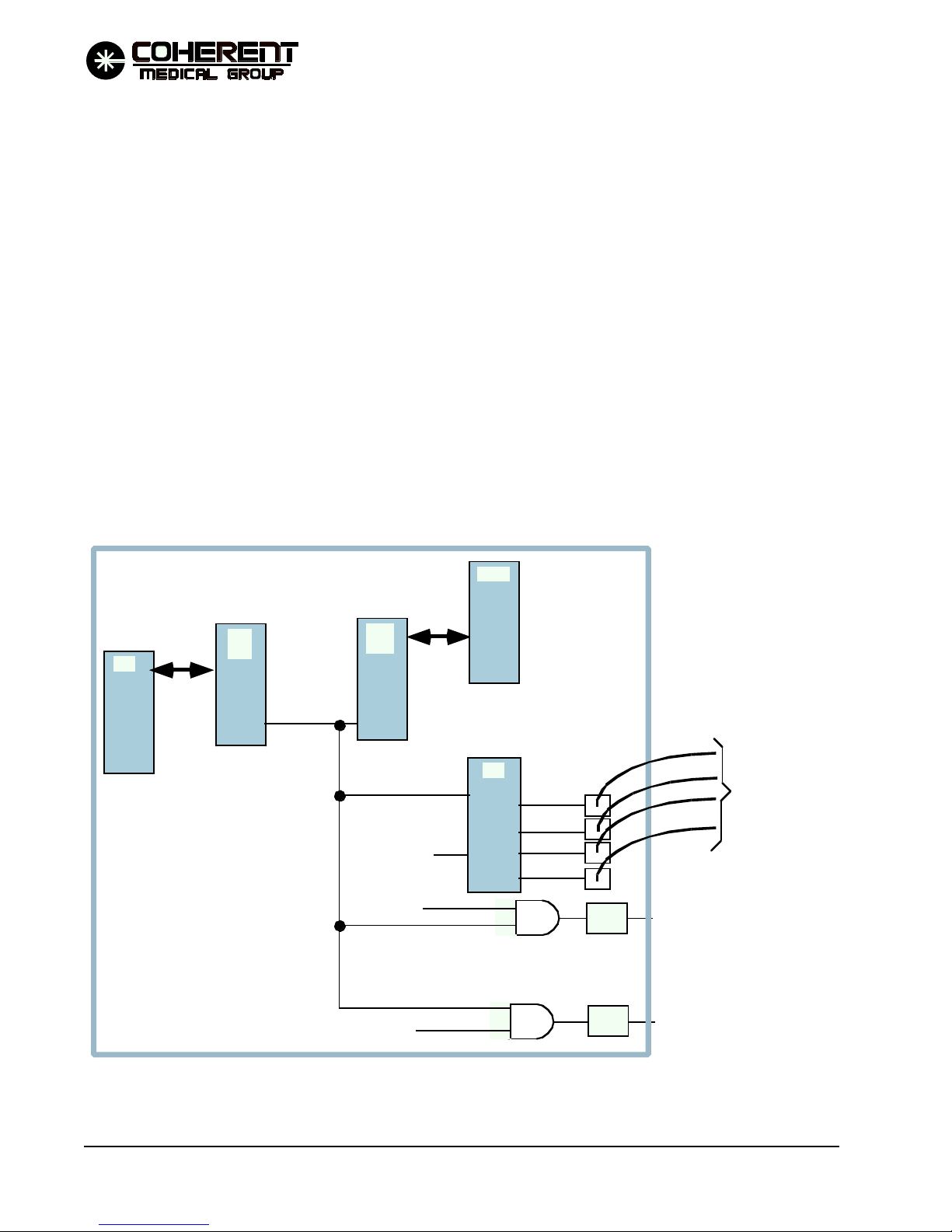
®
®
Reporting the "nofire" condition to the main processor through the main processor digital I/
O at U44 pin 20.
U78 "B" channel operates the three SMUX lines that select the input to the safety processor ADC
circuit at multiplexer U78.
U78 channel "C" provides timing functions for the safety processor, including the 1 msec interrupt.
The safety processor writes to its digital I/O to set the SMUX0, SMUX1, and SMUX2 lines. These three lines
are the select inputs to multiplexer U76. Based on its select inputs, the multiplexer will select one of the four
analog voltages on its input lines for output to analog to digital convertor U68. U68 converts the DC voltage
input to a digital value and stores it in registers U69 and U70. The safety processor can then read in the digital
value representing the analog voltage.
The ADC circuit can read the analog outputs from the energy monitor circuits and the HVDAC voltage.
U93, DIS I and DIS II are used to provide a 2 digit seven segment display for the safety processor. The display
is used in system testing/de-bugging.
P/O CPU PCB
SµP
DIO
SµP
/NOFIRE/
When the /NOFIRE signal is aserted low:
1. Opens the four trigger
outputs from U42.
2. Forces U64-3 low, disabling
the HVPS from charging the main
charging capacitor.
3. Forces the U64-6 low, disabling
drive to the shutter solenoid.
4.) DIO input to main processor.
MµP
DIO
FIREPLS
HVENTM
SHTRDR
MµP
U42
TRIG 1
TRIG 2
TRIG 3
TRIG 4
U64-3
U64-6
MCT6
MCT6
TO ISOLATED
TRIGGER PCB
RS ENABLE
SHTR. DR
FIGURE 4.10 SAFETY PROCESSOR NOFIRE CIRCUIT SIMPLIFIED DIAGRAM
THEORY OF OPERATION
4-26
Versapulse Select Service Manual
0621-499-01 01/94
12/95

®
4.5 FLASH LAMP POWER CIRCUITS
Refer to the Isolated Trigger Board PCB schematic in Section 8, and the HVPS & PFN Interface Circuits
Simplified Block Diagram in topic 4.4.5. The flash lamp power circuits include the HVPS, simmer supply,
isolated trigger circuits, main charging capacitor circuit, flash lamp SCR's and the flash lamps. These circuits
operate together to start and simmer the flash lamps between firings; charge the PFN capacitor before firing;
and then trigger the discharge of the main charging capacitor through the selected flash lamp.
Simmer - The flash lamps are simmered at a low current between pulses simply to maintain the electrical
path to the SCR anode side - i.e., if the lamp was not conducting (open circuit on lamp cathode side) the SCR
could not be gated on. The lamp is simmering but the rod is not simmering. The simmer board provides a
separate simmer supply current for each flash lamp, as well as suppling a transformer coupled RF field
around each flash lamp to promote ionizing of the flash lamp at turn on. The RF field is established by
connecting a transformer secondary to the cavity housing, which is electrically isolated from the chassis. The
Simmer board operates off of 400 VDC supplied by the HVPS. C7, R11 and DS2 provide an indication of the
presence of the 400 VDC supply voltage to the simmer supply board.
Charging the PFN Capacitor - Prior to each YAG pulse the HVPS charges the PFN cap to the level specified
by the Cap charge command voltage signal from the Controller PCB. The range of charge is from 700 to 1400
VDC. The level of charge determines the pulse energy. R1, C1 and DS1 form a charge level indicator. DS1
flashes faster as the level of charge on the capacitor increases.
®
Discharging the PFN capacitor - There are four identical isolated trigger circuits on the Isolated Trigger PCB
- one for each of the four flash lamp circuits. Each has an optical fiber input from the controller PCB, and an
output to its associated flash lamp SCR. All four circuits share a common 30 VDC supply developed by zener
CR1 from the main charging capacitor voltage. All four circuits are functionally the same - the Trigger I
circuit operation will be described in the next paragraph.
To discharge the PFN capacitor through the I flash lamp, the Controller PCB sends a pulse of infrared light
through the optical fiber connected to RECV 1. RECV turns on, turning on its associated FET Q1. Q1 on
connects the 30 VDC through R2 to the gate of an SCR connected between capacitor ground and the cathode
of the flash lamp. The SCR turns on, providing a discharge path for current from the main charging capacitor
through the flash lamp and SCR to capacitor ground.
4.6 OPTICS
The optics include all components that act on the aiming and/or treatment beam. This includes the Ho:YAG
cavity module; Ho:YAG combining optics; folding mirrors; the energy sample optics; shutters; attenuators;
aiming beam laser and combining optics; the fiber focusing lens and blast shield.
Ho:YAG CAVITY - The Ho:YAG cavity provides pulsed output of 2.1 micron wavelength light
energy. The cavity is pumped with a xenon flash lamp. The lasing medium is a Ho:YAG rod. The rod
is positioned between an HR and OC (≈ 15% leakage) mirror. Up to four such cavities can be housed
in a single Versapulse Select system.
MULTIPLEXING OPTICS - The multiplexing optics consist of an imaging and flat mirror for each
cavity, and the servo positioned imaging mirror. For each cavity, an imaging mirror directs the OC
output off a flat mirror to the surface of the servo positioned imaging mirror. The servo positioned
mirror can be rotated to line up with each of the up to four YAG beam paths, so that each output is
directed down a common beam path.
Versapulse Select Service Manual
0621-499-01 01/94
12/95
THEORY OF OPERATION
4-27

®
®
PRIMARY BEAM PATH - the servo positioned mirror output is directed through two folding
mirrors towards the fiber focusing lens. In its path are the following additional optical components.
First Wedge Optic - The wedge optic front and back surfaces each reflect a small portion (≈
0.2%) of the YAG energy back towards an imaging mirror. The imaging mirror is positioned
to direct these reflections upon two pyrodetectors mounted on the Single Solenoid PCB, one
sample to each pyro. The pyro circuitry translates the energy sample into a voltage
proportional to the energy of the Ho:YAG pulse. To maximize the accuracy of the energy
sampling the wedge optic uses a simple coating and a near normal pick off angle. The
imaging mirror maintains a constant image size on the pyrodetector surface over the range of
beam diameters (the beam diameter decreases at higher pulse energies).
Low Power Attenuator - The LP attenuator can be inserted into the beam path to decrease
the treatment beam power. This allows the system to deliver pulse energies lower than the
lowest stable pulse energy available out of the YAG head. Currently the low power
attenuator feature is not implemented by the software.
Second Wedge Optic - A second wedge optic is required to check the power after the low
power attenuator. Although two samples are reflected off the wedge, only one is used. An
imaging mirror directs the sample towards a pyrodetector mounted on the Dual Solenoid
PCB. The pyro circuitry translates the energy sample into a voltage proportional to the
energy of the Ho:YAG pulse.
Service Attenuator - The service attenuator is inserted into the beam path to attenuate the
treatment beam before it is focused into the end of the fiber. It is operated by a switch inside
the unit accessible to the servicing technician. The attenuation is used during alignment
procedures. The system will not operate in user mode if the service attenuator is in the beam
path.
Safety Shutter - Blocks the treatment beam path when de-energized.
Aiming Beam Diode and Combiner Optic - A red (650 nm) aiming beam is provided by a
diode laser mounted in the optical head. The user can turn the aiming beam of or select high,
low, or medium intensity. The diode output is directed by a folding mirror to a beam
combiner in the primary beam path. The combiner and folding mirror are both adjustable to
allow for placing the diode aiming beam coaxial with the treatment beam.
Fiber Focus Lens - Focuses the beam into the fiber.
Blast Shield - Protects the Fiber Focus Lens from debris ejected from the proximal end of the
fiber during a fiber failure.
THEORY OF OPERATION
4-28
Versapulse Select Service Manual
0621-499-01 01/94
12/95

®
4.7 SOFTWARE
There are two microprocessors in the VersaPulse Select: the main processor (Mµp) and the Safety Processor
(Sµp). Each has its own software program. The two programs are not identical, but are interdependant, i.e.,
the software continually requires confirmation/agreement from the other processing system in order to
continue its normal operating sequence. The two software programs are written to require checks with the
other processing system throughout normal operation to confirm that the two systems are in agreement
concerning operating parameters, system status, etc.. When either system fails to receive the expected
communication with the other system, a fault condition occurs and the laser is inhibited from firing. Both
processors have the ability to terminate a laser exposure. Communication is carried out through the DPRAM.
The following software sequence lists describe the operating sequence from the perspective of the main
processer. The safety processor has a similar start up sequence, then monitors system operation, acting to
inhibit laser firing if an abnormal operating condition is detected.
START UP & SELF TEST (main proccessor)
(Refer to the software table on 8-30)
AUTO CAL
®
The system performs a two point calibration for each channel to determine the relation between
flashlamp voltage and pulse energy. The cap voltage values for the minimum and maximum pulse
energy (.5 and 2.8) are determined, then the required voltages for other energies are derived. This is
the calibration data stored in NVRAM. The values found for each channel min and max pulse energy
are displayed on the second service screen.
IDLE LOOP
Check shutter position, power supplies, HVPS voltage and status, coolant, delivery fiber, BRH
connector status.
Check the service switch
Check for activation of any control
Check for exit to firing routine
Go back to start
FIRING
When the footswitch is pressed the main proccessor calculates the appropriate flashlamp voltage
using the selected pulse rate and energy to index the energy-vs-voltage curve stored in NVRAM (the
calibration data). Before each fire pulse the main processor moves the servo mirror, charges the
flashlamp capacitor and directs the firepulse to the appropriate flashlamp.
The fire pulse is triggered by the main processor, but the actual pulse is provided by a hardware
timer. The fire pulse discharges the capacitor through the selected flashlamp, interrupts both processors, and starts a hardware timer that enables the energy monitors. After the pulse, both processors
read the energy monitor signals.
Flashlamp voltage is adjusted according to the energy of the previous pulses, using a set of
mathamatical formulas that generate a correction factor. This is the light feedback function.
Versapulse Select Service Manual
0621-499-01 01/94
12/95
THEORY OF OPERATION
4-29

®
®
After each pulse, the software checks the ENG I and ENG II signals for agreement, and then confirms
that the pulse energy was not excessively high or low. If any of these checks fail, the laser is inhibited
from firing and a fault is displayed on the touch screen.
Pulse interval (the period between the individual laser firings) is generated by a hardware timer.
Between pulses the Mµp checks flashlamp voltage, footswitch condition (is it still depressed?) and the
BRH interlock. In addition it checks one of the following four values on a rotating basis (one between
each pulse): +5 VDC, +12 VDC, -12 VDC, coolant temperature.
THEORY OF OPERATION
4-30
Versapulse Select Service Manual
0621-499-01 01/94
12/95

®
5.0 TROUBLESHOOTING
5.1 OVERVIEW
5.1.1 Service Philosophy
The Versapulse Select is designed to require little adjustment or calibration, and to detect and report hardware
malfunctions by fault code, displayed on the control panel. In most cases field failures are repaired by changing
out a Field Replaceable Unit (FRU). FRU's are built specifically to support field repair, and consist of a part or
group of parts determined to be suitable for field replacement. When a part fails that is a part of a FRU, the FRU
is replaced, not the individual part.
®
Corrective and preventive maintenance must only be accomplished by a Service Engineer who has completed
Coherent certification service training on the Versapulse Select.
Field calibration and adjustment is covered in detail in Section 3. Special purpose tools are required to maintain
the Versapulse Select. These tools are listed in Section 6.
The entire optical path is enclosed inside the laser head. Removing the dust cover exposes the interior to foriegn
matter (dust, cookie crumbs, your hands). Minimize this exposure by removing the cover only when necessary,
using a clear palstic cover over the head while the dust cover is off, and getting the dust cover back on as soon
as maintenance inside the head is complete.
After power up, and before the VersaPulse Select moves to its standby condition, the software performs a series
of self tests. Self test failures result in fault codes displayed at the touch screen. These fault codes provide an
indication of what malfunction was detected, which should point to a specific area of the system for further
investigation. Explanations of the fault codes are included in this section. Most hardware malfunctions will be
detected at this time.
During normal operation the software continues to monitor for system malfunctions, and to report any detected
malfunctions by fault code at the touch screen.
The Versapulse Select has a series of service software routines available to the service engineer. The routines are
contained in the software EPROM, and are activated by pressing a button on the Controller PCB (not accessible
to the user). These routines facilitate calibration and troubleshooting. The routines are described in detail later in
this section.
A service attenuator is built into the optics bench, and can be placed in the beam path by operating a switch on
the Shutter PCB. The service attenuator can be used during servicing to decrease the power of the treatment beam
before it enters the fiber focus assembly. This can prevent damage to an attached fiber and/or the blast shield
when the laser is fired before the fiber focus alignment has been confirmed.
VersaPulse Select Service Manual
0621-499-01 12/95
TROUBLESHOOTING
5-1

®
®
The safety processor circuits include a two digit, seven segment LED display mounted on the CPU PCB. The
software can use this display to indicate status or type of fault information to the service engineer.
There are two indicator bulbs inside the PFN enclosure. One bulb illuminates to indicate that the 400 VDC supply
for flashlamp simmering is present. The other indicator bulb flashes at a rate proportional to the charge on the
main charging capacitor.
5.1.2 Safety Precautions
Lethal voltages and Ho:YAG laser emission are the primary dangers to the Servicing Engineer. In addition to the
general safety precautions which always apply when working on electronics and lasers, the Servicing Engineer
must be aware of the following specific precautions:
Only Coherent certified Versapulse Select Service Engineers should attempt any service on this
system.
Even with the keyswitch in the "OFF" position there are potentially lethal voltages present inside the
console.
Storage capacitors inside the system are capable of holding a lethal charge, even after power has been
removed from the unit.
Do not touch the YAG Cavity Module - IT IS A SHOCK HAZARD. The YAG Cavity Module is
electrically isolated from the chassis ground and connected to the secondary of a transformer to
develop an electrical field around the flashlamps. The YAG Cavity Module is located in the laser head.
The Ho:YAG laser light is invisible to the human eye. Because the Ho:YAG energy can not be seen, there
is no visible indication of the primary or reflected beam. Eye protection that attenuates the Ho:YAG
wavelength to a safe level must be worn by all persons in the area of the laser system whenever the laser
is being serviced.
The Ho:YAG laser light and its reflections are potential burn hazards and can ignite flammable
materials. Use extreme caution when operating the system with covers opened or removed. The covers
contain the beam and reflections safely within the console. Only those persons required should be present
during servicing, and eye protection that safely attenuates the Ho:YAG wavelength must be worn by all
present.
The Ho:YAG laser light and its reflections are potential hazards to the eye. Use extreme caution when
operating the system with the covers opened or removed. The covers contain the beam and reflections
safely within the console. Only those persons required should be present during servicing and eye
protection that safely attenuates the Ho:YAG wavelength should be worn by all those present.
TROUBLESHOOTING
5-2
VersaPulse Select Service Manual
0621-499-01 12/95

®
5.2 INTERIOR ACCESS & PART LOCATIONS
Interior access is gained through the front cover (door), which is hinged on the right side side. Once the front cover
is opened, the top cover can be removed. Once the top cover is removed the two side panels can be removed. There
is an electrical cable running between the left side panel and the console (for the key switch and emergency off
button). When removing this side cover, use caution to prevent stressing the cable. A connector allows the cable
to be disconnected to free the side cover completely (but the system will not turn on if this connection is broken).
Open the front cover to access the two DC power supplies (mounted inside the door), to access the Controller PCB,
or to remove the top cover or either side cover.
To open the front cover, insert a small tool (such as a hex key) through the hole on the bottom left of the front cover.
Push up on the tab inside the hole to release the cover (it is hinged on the right side).
®
FRONT DOOR CLOSED
FRONT DOOR OPENED
CONTROLLER PCB
LOW VOLTAGE
DC P/S
R
R
Insert a small tool (hex wrench)
through the hole on bottom left
of front door panel. Push up on
the tab inside the hole to release
the door. Door will swing open
towards the right.
VersaPulse Select Service Manual
0621-499-01 12/95
DISPLAY P/S
FIGURE 5.1 FRONT VIEWS
TROUBLESHOOTING
5-3

®
®
TO POWER SUPPLY
To Isolated
Trigger PCB
XTRM2
XTRM3
XTRM4
J5
J4
XTRM1
R36
To Temperature and conductivity sensors
TO HVPS
To OPTICS PLATE and
FOOTSWITCH/BRH
J2
J1
R8
R9
U89 U88
R7
TP1 - INTEGRATE
TP2 - ENG1
TP3 - ENG2
TP4 - ENG3
TP5
TP6 - +5M
TP7 - +12
TP8 - -12
TP9 - TEMP
TP10 - COND
TP11 - CAPVOLTS
TP12 - DIGITAL GROUND
TP13 - ANALOG GROUND
SW1
(service)
SW2
(reset)
SW3
(autocal)
TROUBLESHOOTING
5-4
U52
U53
R98
up = enable
down = disable
FIGURE 5.2 CPU PCB LAYOUT
SAFETY PROCESSOR
DISPLAY
J9
To Touch Screen Display
J8
RS232 Port
J27
To Beeper
To Servo Motor Control
J7
J6
To Remote Control
VersaPulse Select Service Manual
0621-499-01 12/95

AC IN
®
®
DISPLAY, DC POWER SUPPLY AND DISPLAY P/S
FUSE (5A, 250V)
DC POWER SUPPLY
DC VOLTAGES
OUT
AC IN
INTERNAL 4A, 250V LITTLE FUSE
DISPLAY POWER SUPPLY
DISPLAY
VOLTAGES
FIGURE 5.3 DISPLAY, DISPLAY POWER SUPPLY & LOW VOLTAGE POWER SUPPLY LAYOUTS
VersaPulse Select Service Manual
0621-499-01 12/95
TROUBLESHOOTING
5-5

®
®
Remove the top cover to access the laser head (optics bench), to access the coolant fill reservoir or to remove either
side cover.
To remove the top cover, first open the front cover, then remove the two screws located as shown in the drawing
below.
Cover lifts off
Remove these two
xxx screws.
FIGURE 5.4 REMOVING THE TOP COVER
Remove optics bench cover to access the Shutter PCB, Single Solenoid PCB, Dual Solenoid PCB, Servo PCB and
all of the optical component. Removing the cover exposes the optics bench to airborne contamination. The optics
that operate on the YAG beam are particularly susceptable to damage associated with optics surface contamination. Remove this cover only when necessary. If the cover must be removed, be careful to minimize exposure of
the optics bench interior to external contamination.
To remove the head cover, loosen the screws located along the bottom edge of three sides, then lift the cover up.
TROUBLESHOOTING
5-6
VersaPulse Select Service Manual
0621-499-01 12/95

®
®
OVERHEAD VIEW, LASER HEAD
with head cover removed
2ND FOLDING
MIRROR
SERVO
PCB
SERVO AND
FIRST MIRROR
WALL
SHUTTER
PCB
SW1
OC & SECOND
MIRROR WALL
SINGLE
SOLENOID
PCB
PYRO
IMAGING
MIRRORS
FIRST FOLDING
MIRROR
WEDGE
OPTICS
YAG CAVITY
MODULE (up to four
cavities installed)
DUAL
SOLENOID
PCB
DIODE
LASER
(AIMING)
Terminal connections
for flash lamp leads.
FIBER
FOCUS
BLAST
SHIELD
HR WALL
YAG IV
VIEW FROM
OC END
Nonconductive
mounting plate.
CAUTION: The Cavity Module
can be at a high voltage potential.
Do not touch .
FIGURE 5.5 OPTICS BENCH & LASER HEAD LAYOUT
VersaPulse Select Service Manual
0621-499-01 12/95
YAG I
YAG IIYAG III
BACK SIDE TERMINAL CONNECTIONS:
ANODE OUT
ANODE OUT
BLANK
LASER 4 CATHODE OUT
LASER 3 CATHODE OUT
LASER 2 CATHODE OUT
LASER 1 CATHODE OUT
FRONT SIDE TERMINAL CONNECTIONS:
ANODE OUT
ANODE OUT
ANODE IN
LASER 4 CATHODE IN
LASER 3 CATHODE IN
LASER 2 CATHODE IN
LASER 1 CATHODE IN
TROUBLESHOOTING
5-7

®
®
YAG ROD
FLASH LAMP
HR END - (flashlamp anode RED LEAD)
O ring
FIGURE 5.6 YAG CAVITY LAYOUT
OC END (flash lamp cathode, BLACK LEAD)
End Seals
Dual Solenoid PCB
Single Solenoid PCB PCB)
J13
J14
TROUBLESHOOTING
5-8
SERVICE
SWITCH
J16
(Service Attenuator)
J15
J12
Aiming Footswitch
laser interlock
FIGURE 5.7 SHUTTER PCB LAYOUT
J11
(To J1 on controller
VersaPulse Select Service Manual
0621-499-01 12/95

CR3
®
®
CR2
LPT1
J17
(To J14 Shutter PCB)
Service Attenuator
normally open
LP ATTENUATOR
(NOT CURRENTLY USED)
FIGURE 5.8 SINGLE SOLENOID PCB LAYOUT
LPT1
ATTENUATOR
CR4
SERVICE
VersaPulse Select Service Manual
0621-499-01 12/95
CR3
LPT3
LPT2
J18
(TO J-13 ON SHUTTER PCB)
SHUTTER
FIGURE 5.9 DUAL SOLENOID PCB LAYOUT
TROUBLESHOOTING
5-9

®
®
Remove the right side cover to access the fuses, main contactor, Isolation Transformer Terminal Board, the circuit
breaker, HVPS, K1, K2, and to access the interior of the PFN enclosure.
To remove the right side cover, open the front cover, remove the top cover, remove the single screw that secures
the cover at the bottom just in front of the rear wheel, then remove the six screws along the top and front of the
cover (three along the top, three along the front). The cover can then be lifted off of the frame.
AC Terminal
block for H
pump
TOUCH SCREEN
CONTROL PANEL
SMART FAN PCB
2
0
INSIDE THE PFN
COVER PLATE
Main charging Cap +
DS1
Main charging cap -
FUSE BLOCK
B
F2 F3
F1
OPTICS BENCH
PFN
ENCLOSURE
HVPS
F4 F5 F6 F7 F8 F9
FUSES
COOLING FAN
HEAT EXCHANGER
MAINS (F1)
K2
K1
MAIN
RESERVOIR
AC inputs to
transformer.
FILL RES.
CHASSIS
GROUNDING
POST
CIRCUIT
BREAKER
MAIN
CONTACTOR
BACK
CONDUCTIVITY
SENSOR
TO
XFORMER
(primary)
120
100
VAC Inputs
200 VAC
220 VAC (Std.)
240 VAC
16A 16A
A
4A 4A 4A 4A 10A 10A
FIGURE 5.10 INTERIOR VIEW, RIGHT SIDE
TROUBLESHOOTING
5-10
10A
MAINS (F2)
120
100
All 30A
@ 60Hz
breaker
VersaPulse Select Service Manual
0621-499-01 12/95

®
Remove the left side cover to access most of the cooling system components.
To remove the left side cover, open the front cover, remove the top cover, remove the single screw that secures
the cover at the bottom, just in front of the rear wheel, remove the six screws along the top and front of the cover
(three along the top, three along the front), then carefully pull the cover off to access the jack and plug connection
on cable that runs out to the key switch and emergency off button, both located on the cover. If the system is to
be operated with the cover off, the cover will need to be placed close enough to the unit to allow the keyswitch
and emergency off button connection to remain connected.
TOUCH SCREEN
CONTROL PANEL
FILL RES.
OPTICS BENCH
®
TEMP SENSE
(DISPLAY)
FLOWSWITCH
FILTER
D/I FILTER
BACK
COOLING FAN
MAIN
RESERVOIR
HEAT EXCHANGER
PFN
ENCLOSURE
FRONT
HVPS
Connector to Left Side
Cover.
TEMP SENSE
VersaPulse Select Service Manual
0621-499-01 12/95
FIGURE 5.11 INTERIOR VIEW, LEFT SIDE
TROUBLESHOOTING
5-11

®
®
5.3 SERVICE MODE
The VersaPulse Select includes "service mode" software routines. Service mode provides the Servicing Engineer
with a number of troubleshooting and maintenance aids. Some system faults are ignored in service mode (see
5.4.3).
To enter service mode, the main processor and safety processor must see an off to on transition of CPU PCB SW1.
SW1 is the uppermost of the three switches located on the bottom left side of the CPU PCB. Note that if the switch
is left on when the system is powered up, it will not enter service mode (no off to on transition). If the processors
are halted (some faults are handled by halting the processor) the service switch will not work - restart the
processors (press reset switch SW2 on the CPU PCB) then toggle the service switch off to on.
Upon entering service mode the touch screen displays the first service screen (see figure 5-12). The first screen
includes the following functions:
AIMING BEAM CONTROL - sets the aiming beam to any of its four intensities (off, lo, med, high).
RATE CONTROL - set the firing rate from 5 to 40 Hz.
VOLTAGE CONTROL - sets the cap charge voltage from 700 to 1500 Volts.
READY/STANDBY SELECT
YAG HEAD ON/OFF SELECT - there is an on/off control for each YAG rod. Turning a rod off means
that it will not be triggered during a firing sequence. This allows for operating only one rod, or any
combination of rods.
Turning off a rod will result in a "skipped beat" out of each four pulses, e.g., if 40 Hz is selected
with one rod turned off, the pulse interval will be normal for three pulses, and then be doubled
(the rod turned off doesn't fire), then three more pulses and a double interval, and so on. The
irregular interval that results from having rods turned off is easily heard.
Turning rods off effects average power and the effective pulse rate, e.g., if only one rod is on, a
selected pulse rate of 40 Hz, will result in an actual pulse rate of 10 Hz, and an average power
approximately one fourth that @ 40 Hz (approximate in service mode because the rods are all
fired at the same cap voltage in service mode, and will have different energy outputs).
Once a rod is turned off in service mode, it remains off, even if the system is returned to user mode
or turned off and then back on.
AVERAGE POWER DISPLAYS - Each time the system is fired in service mode the three energy monitor
outputs are used to maintain an average power for each of the four rods. When the footswitch is released
these displays will be updated, showing the average power as determined by the three energy monitors
for each of the four heads. This is convenient for checking relative rod performance (all rods were fired
at the same cap voltage) and for checking for agreement between the three energy monitor circuits.
NEXT SCREEN - touch to move to the second or third screen.
Press the "RESET" button if "CALIBRTE" was pressed in error.
TROUBLESHOOTING
5-12
VersaPulse Select Service Manual
0621-499-01 12/95

FIRST SERVICE MODE SCREEN
®
®
aiming beam
status
OFF
AI M MA X
AIM UP
AIM DN
AI M OF F
ON
3.2 5 Wat ts
3.2 1 Wat ts
3.2 2 Wat ts
selected rate
5 HZ
JUMP U P
RATE UP
RA TE DN
JUMP DN
ON
0.0 0 Wat ts
0.0 0 Wat ts
0.0 0 Wat ts
selected cap
charge voltage
700 V
JUMP U P
VOLTS UP
VOLTS DN
J UMP DN
ON
0.0 0 Wat ts
0.0 0 Wat ts
0.0 0 Wat ts
NEXT SCREEN CALIBRA TE
selected mode
(r eady or standby)
STAN DBY
0.00 Watts
0.00 Watts
0.00 Watts
READY
READY
ON
PARAMETER DISPLAY
TOUCH CO NTR OLS
FO R T H E PARA M E TE R
DISPLA Y ED ABOVE
THEM.
YAG HEAD SELECT/D ESELE CT
TO UC H CONTROLS
(YAG I thru IV, left to right)
AVERAGE POW ER CALCULAT ED
FROM LAST FIRING ( ENG I, II, III)
(YAG I THRU IV, right to left)
as measured by the pyro detectors
TO UC H C ON T ROL S T O MOVE
TO NEXT SCREEN, ENTER
AUTOM A T IC L AS ER
C A LIBR AT ION RO UTIN E
SECOND SERVICE M ODE SCREEN
5V 4.99
+12 1 2.00
-12 12.0 0
TEMPC 29.8
COND µS 0 .3
.5J 821 84 4 866 838
2.8J 14 21 143 3 141 1 1 4 15
NORMAL
SHUTTER MODE
ENGLIS H
NEXT SCREEN
LE Att enuator
IN/O UT
PARAMETER
DIS PLA YS
CAL POINTS (M IN & MAX)
(YAG I THRU IV, lef t to r ight)
TOU CH C ONTROL & DIS PLAY
FOR SH U T T ER MODE
TOU CH C ONTROL & DIS PLAY
FOR LANGUAGE
TOUCH CONTR O L TO M OVE
BAC K TO SCREEN ONE
VersaPulse Select Service Manual
0621-499-01 12/95
TROUBLESHOOTING
5-13

®
®
CALIBRATE - touch to select the automatic laser calibration routine. "CALIBRATE" will be displayed
near the top of the screen. Depress the footswitch and hold it down to start the automatic laser calibration.
During calibration the system fires the rods to find eight values - two for each rod. The values are the cap
charge that will provide the lowest selectable pulse energy and the capacitor charge voltage that will
provide the highest selectable pulse energy (2.8 joules). The process takes just a few seconds. After
completion a message will appear on the screen indicating that the calibration is complete (the value
found can be viewed on the second service screen).
The second screen provides the following functions:
5V/±12V - displays the main processor ADC measurement for the DC power supply voltages.
TEMP C - displays the coolant temperature in degrees C.
CONDUCTIVITY - displays the coolant conductivity in µS.
MIN/MAX CAP CHARGE VOLTAGES - displays the cap voltages required to obtain min pulse energy
and maximum pulse energy for each head.
SHUTTER MODE - touch to select normal or service. In service mode the shutter can be moved by hand
without causing a system fault. This allows the slotted optical switch outputs to be checked.
LANGUAGE - touch to select displayed language Elglish/German/French.
Note: The service mode software screens are always in English.
NEXT SCREEN - touch to go to the first screen.
5.4 FAULT ISOLATION
Failures/malfunctions fall into the following general categories:
The system fails to turn on properly, or shuts off when it should not. See section 5.4.1.
The system turns on, but the Control Panel displays and/or operating controls do not respond properly,
and no fault code is displayed. See section 5.4.2
During power up tests, or during operation, the system displays one or more error codes. See section
5.4.3.
During power up self tests the system fails to pass autocalibration See Section 5.4.4
TROUBLESHOOTING
5-14
VersaPulse Select Service Manual
0621-499-01 12/95

®
5.4.1 TURN-ON AND SHUTDOWN FAULT ISOLATION
System "turn-on" problems occur when the system fails to turn on and stay on with activation of the key switch.
System "Shutdown" refers to the system main contactor de-energizing after the system has successfully turned
on.
If the system fails to turn on, determine if there is power to the unit and through the circuit breaker to the main
contactor and isolation transformer. Determine if the main contactor is energizing when the keyswitch is held
in the start position (do the system fan and pump start running?). If not, check the circuit breaker, isolation
transformer thermal switch, front door interlock, and fuses F1/F2. If the contactor is energizing in the start
position, but de-energizing when the keyswitch is released, check for sufficient coolant flow (coolant level, pump,
line restrictions, etc.), waterflow switch S3, K2 and K1 (Refer to Interlock schematic in Section 8).
If the system shuts down after being turned on, and the circuit breaker is not tripping, use the Interlock schematic
in Section 8 to troubleshoot the main contactor interlock loop. Note that the software and main/safety processors
can not turn off the main contactor. The 24 VAC loop to the main contactor can be broken by the thermal switch
in the isolation transformer, the waterflow switch, the front door interlock switch, hold on relay K2, or the fuse
F3.
If the circuit breaker is tripping, check for proper transformer tapping. If the tripping is associated with firing (or
charging of the main capacitor), it is probably associated with the HVPS. If not, attempt to isolate the tripping
to one of the isolation transformer secondary loads by removing fuses until the circuit breaker no longer trips
(smart fan fuse, pump fuse, display P/S fuse, DC P/S fuse, then interlock loop fuse). If the breaker trips with the
isolation transformer primary side fuses removed, there is probably a problem with the HVPS or mains
components.
®
5.4.2 "NO FAULT CODE REPORTED" FAULT ISOLATION
Some system malfunctions cannot be reported at the Control Panel. These include those malfunctions which
interfere with the operation of the microprocessor, malfunctions in the hardware that drives the display used to
report errors, and miscellaneous circuits/functions which are not directly monitored/tested by the software.
If the malfunction is associated with a particular function (e.g., the system doesn't respond to the footswitch, or
to some front panel control), troubleshoot that function, referring to the circuit descriptions in Section 4.
If the system turns on, but the malfunction is more general (e.g., the self test sequence doesn't run, Control Panel
does not respond) check for proper DC power supply voltages, isolation transformer tapping, interconnection
problems, or for some problem with the microprocessors (are they running?)/Control Panel interface. If the
problem can not be isolated to a particular circuit, replace the CPU PCB.
5.4.3 "FAULT CODE REPORTED" FAULT ISOLATION
The safety processor monitors the system to detect and respond to various fault conditions. When a fault is
detected, the safety processor displays the fault directly on the CPU PCB (as a two digit hexadecimal number on
the two seven segment LED's) and notifies the main processor of the fault. The main processor updates the touch
screen to display the fault code and any accompanying message at the touch screen. Multiple faults are displayed
sequentially, and repeatedly.
VersaPulse Select Service Manual
0621-499-01 12/95
TROUBLESHOOTING
5-15

®
®
These fault conditions can be informational, clearable, or permanent.
Informational faults notify the user of some detected abnormal condition that is not significant enough
to interfere with system operation. An advisory message is displayed on the touch screen and the system
continues to operate.
Clearable faults interrupt system operation and force the system to STANDBY, but have the potential to
be cleared by some user action. Some clearable faults include messages to indicate an action required by
the user, e.g., "ATTACH FIBER" appears on the touch screen if there is no fiber attached. Other clearable
faults advise of some detected abnormal condition, but require no further action by the user other than
selecting READY to clear the error. Finally, the coolant conductivity and overtemperature errors will not
clear until that parameter falls back into acceptable limits. The user can't clear these faults directly. Note
that a clearable fault will return if the condition that caused it occurs again or is still active.
Permanent faults place the system in a safe, nonfiring condition that can not be cleared without re-starting
the system. Restarting the system will clear the fault, but if the detected condition is still present, the fault
will occur again.
Some faults are ignored in service mode to aid in troubleshooting. Some faults are only checked during the self
test sequence that occurs at start up. Such faults are so identified in the description of the fault.
Begin by getting a detailed understanding of the symptoms. For example, does the fault appear during self testing
or during normal operation; Does the fault occur only when firing; Only at certain energy or pulse settings; is the
fault easily repeatable or is it intermittent? It is always worthwhile to check for proper mains input, proper
transformer tapping, proper DC voltage supply outputs, and to perform a careful visual inspection for loose
connections and visual indications of problems.
The following list defines the fault codes and provides troubleshooting information for each. The two characters
in parentheses following the bold text is the hexadecimal number that appears on the CPU PCB display when the
fault occurs. Clearable faults are cleared by pressing seleting READY.
F1 - ADC REMAINS BUSY TOO LONG - The CPU PCB analog to digital convertor (U20) or its associated
circuitry is malfunctioning. Check DC voltages, connections to the CPU PCB. If problem persists, change the CPU
PCB.
F2 - UART DETECTED BREAK CONDITION - The CPU PCB main processor UART (U29) is detecting an
abnormal condition on at least one of its receive ports. The display and remote control receive and transmit data
to the Main Processor UART. This could be a problem with the CPU PCB, Remote Control, or Display.
F3/4 - DIGITAL I/O FAILURE - The main processor digital I/O is malfunctioning (F3 is U43, F4 is U44).
F5 - CAP VOLTS WRONG - The output of main processor DAC U10 is used as the charge level command to the
HVPS. The main processor writes a digital value to the DAC, then checks the DAC output through its ADC circuit
to insure that the DAC output is correct. If not, this error occurs. If this error persists, change out the CPU PCB.
If another lamp fires out of sequence due to noise the cap will not have the correct charge. This error will (or may)
occur. Check the trigger board for ground line and diode modifications. The white wire on the J53 connector may
have to be removed.
TROUBLESHOOTING
5-16
VersaPulse Select Service Manual
0621-499-01 12/95

®
F6 - COOLANT CONDUCTIVITY WRONG - The coolant conductivity is monitored to minimize corrosion
inside the coolant system. If the coolant conductivity is excessive, this fault will occur. This fault may occur if
a system is turned on after being off for an extended period, the water added as coolant is not deionized,
something inside the coolant loop is contaminating the coolant, or the DI filter needs to be replaced. If the fault
occurs at turn on, leave the system on; this allows the DI filter to lower the coolant conductivity. If this fault
persists, change the DI filter.
F7 - COMMUNICATION DATA ERROR - Not implemented in current software.
F8 - CPU ERROR - The Main Processor has failed. Check the DC supply voltages. If the fault persists, change
out the CPU PCB.
F9 - INCORRECT ECHO OF TRANSMITTED CHARACTER - Not implemented in current software.
F10 - E1 AND E2 DISAGREE - After a fire pulse, the voltage signals from the two energy monitor circuits E1 and
E2 are different. When properly calibrated, both circuits will output ≈ x VDC/joule of energy. Check the energy
monitor calibration. The two signals can be seen on an oscilloscope at CPU PCB test points (TP2 TP3). Both
pyrodetectors are located on the Single Solenoid PCB. The samples are picked off the main beam path (2.22V/
Joule) by a wedge optic, then directed to the pyrodetector surface through an imaging mirror.
®
F11 - ERROR PROCESSOR ERROR - The error processor is actually a software routine. If this error persists
change out the CPU PCB.
F12 - SPURIOUS FIRE PULSE INTERRUPT - A fire pulse interrupt has occurred when none was expected. This
does not indicate that any laser energy has been produced, but just that the fire pulse signal as read by the main
processor interrupt circuit has seen the /FIREPULSE/ line go active. If this problem persists, replace the CPU
PCB.
F13 - UART DETECTED FRAMING ERROR - The CPU PCB main processor UART (U29) is detecting an
abnormal condition on at least one of its receive ports. The display and remote control receive and transmit data
to the Main Processor UART. This could be a problem with the CPU PCB, Remote Control, or Display.
F14 - HVPS ERROR - The HVPS has reported one of its three faults to the CPU PCB. The three faults are
temperature overload, current overload, or no charge reversal.
F15 - MAIN PROGRAM DEAD - This fault indicates a problem on the CPU PCB. Swap out EPROMs.
F16 - NEGATIVE 12 VDC WRONG - Check/adjust the -12 VDC.
F17 - NONEXISTENT ERROR CODE - Change out the CPU PCB if this fault persists.
F18 - UART DETECTED OVERRUN ERROR - The CPU PCB main processor UART (U29) is detecting an
abnormal condition on at least one of its receive ports. The touch screen and remote control receive and transmit
data to the Main Processor UART. This could be a problem with the CPU PCB, remote control, or touch screen.
F19 - POSITIVE 5 VDC WRONG - Check/adjust the 5 VDC.
F20 - UART DETECTED PARITY ERROR - The CPU PCB main processor UART (U29) is detecting an abnormal
condition on at least one of its receive ports. The touch screen and remote control receive and transmit data to
the main processor UART. This could be a problem with the CPU PCB, remote control, or touch screen.
VersaPulse Select Service Manual
0621-499-01 12/95
TROUBLESHOOTING
5-17

®
®
F21 - POSITIVE 12 VDC WRONG - Check the +12 VDC.
F22 - ROM CRC CHECK FAILED - This check is done during self test only. Software EPROM has failed the self
test. If this fault persists change out the CPU PCB or swap out the EPROMs.
F23 - SAFETY RELATED DATA ERROR - If this fault persists, change out the CPU PCB.
F24/F25 - SHUTTER DRIVE STUCK ON/OFF - These two checks are done during the self test sequence. Refer
to figure 4.2 (in Section 4). Stuck on indicates that the SHTR DR SNC line is at 24 VDC when the SHTR DR signal
is not active (The Q2 transistor is on when it should not be). Stuck off indicates that the SHTR DR SNC line is not
at 24 VDC when the SHTR DR signal is active (the Q2 transistor is not on when it should be).
F26 - SERVO ERROR - This check is done during self test only. The servo controller has test operated the servo
system and found a problem. This could be a problem with the 24 VDC supply voltage, the Servo Amp PCB, the
motor, the position sense, or the CPU PCB.
F27 - SOFTWARE ERROR - If this error persists, replace the software EPROMs or CPU PCB.
F28/29 - SAFETY SHUTTER NOT CLOSED/OPENED - The safety shutter SHTR DR SNC line has indicated that
the shutter voltage is present (shutter open) or not present (shutter closed) when it should not be. This could be
a problem with the safety shutter (Dual Solenoid PCB), Shutter PCB, footswitch, CPU PCB or the 24VDC supply.
F30/31 - not used
F32 - CAP FEEDBACK WRONG - This check is done during self test only. The DAC output is ramped up through
its range of operation, and read back through the ADC across the range. If the ADC readback differs from the
command sent to the DAC, this error occurs. If the error persists, change out the CPU PCB.
F33 - HCTL SERVO CONTROLLER BUSTED - This check is done during self test only. CPU PCB U30 (the servo
controller) has failed its self test. If this error persists, replace the CPU PCB.
F34 - DPRAM DATA INCORRECT - The dual port RAM has a problem. If this fault persists, replace the CPU
PCB.
F35 - NOFIRE - The /NOFIRE/ signal has been asserted.
F36 - SAFETY PROCESSOR ERROR - If this fault persists, replace the CPU PCB.
F37/F38 - ENERGY HIGH/LOW - The energy of a single pulse is more than two times (F37) or less than half (F38)
of the requested energy.
F39 - NO LASER ENERGY -
F40/41 - PULSE RATE HIGH/LOW - The pulse rate is more than twice of that requested (F40) or less than half
of that requested.
F42 - UNEXPECTED FIRE PULSE - A fire pulse was detected when one was not expected. If this fault persists,
replace the CPU PCB.
TROUBLESHOOTING
5-18
VersaPulse Select Service Manual
0621-499-01 12/95

®
F43 - DPRAM HANDSHAKE FAILURE - The dual port RAM has a problem. If this fault persists, replace the
CPU PCB.
F44 - MAIN PROCESSOR & SAFETY PROCESSOR FIRING PARAMETER MISMATCH - Replace the CPU
PCB if this fault persists.
F45 - DPRAM FAILED TEST - This check is done during self test only. The dual port RAM has a problem. If this
fault persists, replace the CPU PCB.
F46 - ATTACH FIBER - Attach the fiber to clear this fault.
F47 - ATTACH FOOTSWITCH - Attach the footswitch to clear this fault.
F48 - CHECK FOOTSWITCH - This check is done during self test only. The footswitch is depressed during self
testing. (This may also be reported if the footswitch is pressed during turn on or system initialization).
F49 - SYSTEM INACTIVE - The system goes to STANDBY if left in READY for five minutes without use. (This
is not a fault).
®
F50 - REMOTE INTERLOCK - The remote interlock loop is not completed.
F51 - NO CONTROL PANEL - The touch screen display is not responding. Check cable connections, the display
power supply, the touch screen display, and the CPU PCB.
F52 - OVERHEATING - This fault occurs when coolant temperature reaches 35˚C and resets when temperature
falls back down to 32˚C. The temperature monitoring circuit is calibrated as outlined in Section 3. Check Smart
Fan PCB, Fan motor, pump, and water level. Calibrate the TEMP set on the CPU PCB.
F53/F54 - PERFORMING SELF TEST/SEMAPHORE - Not error codes
F55 - NOT CALIBRATED - This check is done during self test only. The system doesn't have calibration data
stored in memory. The auto calibration routine must be run.
F56 - FAILED ENERGY SAFETY TEST - This check is done during self test only. The safety processor failed to
detect a forced incorrect pulse energy level during self test. The test includes a forced >2 times requested energy
and forced less than half requested energy. The safety processor must detect and respond to both., or this fault
will occur. If this fault persists, check the power out of the system, check the energy monitor circuit calibration,
run the autocalibration. (This may be related to fault 5).
F57 - FAILED INTERVAL SAFETY TEST - This check is done during self test only. The system failed to detect
a forced incorrect pulse interval during self test. The test includes forced .8 times and 1.2 times requested pulse
intervals. The safety processor must detect and respond to both, or this fault will occur. Replace the CPU PCB
if this error persists.
F58 - NVRAM CHECKSUM - This check is done during self test only. The NVRAM has failed a checksum check
during self testing. If this fault persists, replace the CPU PCB. The Lithium battery in NVRAM could be expired
or +5V too high. Check the power supply.
VersaPulse Select Service Manual
0621-499-01 12/95
TROUBLESHOOTING
5-19

®
®
F59 - SYSTEM DATA INCORRECT - This check is done during self test only. There is a disagreement the
software EPROM version installed and the information on EPROM software version stored in NVRAM.
F60 - ENERGY MONITOR ERROR - The safety processor and main processor have had a conflict in the shared
use of the energy monitor circuits. Replace the CPU PCB if the fault persists.
F61 - PROGRAM FLOW ERROR - Replace the CPU PCB if this fault persists.
F62/63 - ENERGY 20% HIGH/LOW - (information only, active in service mode)
F64/65 - RATE 20% HIGH/LOW - (information only, active in service mode)
F66 - FRONT PANEL COMMUNICATIONS TIME OUT - The front panel has not responded in time to a query
from the main processor.
F67 - SOFTWARE TIMING - A firing pulse has been missed because the software did not complete all the tasks
necessary in time for the correct pulse interval.
F68 - BLAST SHIELD IS NOT INSERTED - The microswitch that detects the blast shield position is indicating
that the blast shield is not inserted.
F69 - ONE OR MORE FLASHLAMPS NOT LIT - (permanent, active in service mode)
F70 - NOFIRE TEST FAILED - (pemanent, active in service mode)
F71 - AUTOCALIBRATION DISABLED - SW3 is in the down position.
F72 - SERVICE ATTENUATOR IN THE BEAMPATH - The service attenuator is energized. The service
attenuator is controlled by a switch mounted on the Shutter PCB.
F77 - LOW ENERGY ATTENUATOR COATING DAMAGED - With the low energy monitor in the beam path,
the energy measured at the low energy attenuator output is not 40% of the energy measured at the input. Press
READY to clear this fault.
F78 - THE SYSTEM TRIED TO FIRE THE WRONG LASER - Press READY to clear this fault.
F79 - OVERTIME - A timed exposure exceeded its time limit. Press READY to clear this fault code.
F80 - ATTACH HOLMIUM FIBER - Holmium is selected, but the fiber attached is not recognized as the smart
fiber (Hall effect does not sense magnetic field).
F81 - LOW ENERGY ATTENUATOR NOT IN CORRECT POSITION - The position sensors (slotted optical
switches) indicate the low energy attenuator is not in the correct position. Press READY to clear this fault code.
F82 - FAILED TO DETECT A FORCED OVER EXPOSURE - Detected during self test. Restart the system to clear
this fault code.
TROUBLESHOOTING
5-20
VersaPulse Select Service Manual
0621-499-01 12/95

®
F83 - FAILED TO DETECT A FORCED INCORRECT LASER FIRING - Detected during self testing. Restart
the system to clear this fault code.
F86 - CHANNEL 1 IS TURNED OFF - Cycle the system off/on to re-enable channel 1 or continue to use the system
at a reduced pulse rate. If cal. volts is less than 1450 VDC, the fault may be caused by a noise related problem.
If this fault persists check the channel optics, alignment, flash lamp and rod.
F87 - CHANNEL 2 IS TURNED OFF - Cycle the system off/on to re-enable channel 2 or continue to use the system
at a reduced pulse rate. If cal. volts is less than 1450 VDC, the fault may be caused by a noise related problem.
If this fault persists check the channel optics, alignment, flash lamp and rod.
F88 - CHANNEL 3 IS TURNED OFF - Cycle the system off/on to re-enable channel 3 or continue to use the system
at a reduced pulse rate. If cal. volts is less than 1450 VDC, the fault may be caused by a noise related problem If
this fault persists check the channel optics, alignment, flash lamp and rod.
F89 - CHANNEL 4 IS TURNED OFF - Cycle the system off/on to re-enable channel 4 or continue to use the system
at a reduced pulse rate. If cal. volts is less than 1450 VDC, the fault may be caused by a noise related problem If
this fault persists check the channel optics, alignment, flash lamp and rod.
®
VersaPulse Select Service Manual
0621-499-01 12/95
TROUBLESHOOTING
5-21

®
6.0 SELECTED PARTS
The Bill of Materials for the VersaPulse Select series is maintained under document control at Coherent
Medical Group in Palo Alto, California, and is subject to change. The following list is provided for convenience - always confirm the P/N for a given part through Technical Support before ordering.
0623-002-01 ASSY, FIBER FOCUS, MACHINED HEAD, Er ONLY
0623-846-01 ASSY, FIBER FOCUS, MACHINED HEAD, Ho ONLY, FRU
0619-409-01 BEZEL, FRONT, WHITE (AROUND THE DISPLAY PANEL)
BLASTSHIELD, Er, VPSEL, FRU
0624-015-01 BLASTSHIELD, Ho/Nd, VPSEL, FRU
5108-0120 BREAKER, CIRCUIT, 30A, 250V
0619-668-01 BUMPER, FRONT DOOR
0621-057-01 BUMPER, SIDE PANEL
5102-0123 BUTTON, SWITCH, RED, EMERGENCY OFF
6008-0026 CABLE, FIBER OPTIC, 9FT
6001-1473 CABLE, HIGH VOLTAGE, 30kV (PFN TO LASER POD)
1504-0178 CAPACITOR, 2.0kVDC, PFN, CHARGING, Ho/Nd
1504-0179 CAPACITOR, 3.5kVDC, PFN, CHARGING, Er
2601-0145 CAPACITOR, MOTOR, FAN
0613-783-01 CARTRIDGE, DEMINERALIZER, WATER
2603-0124 CARTRIDGE, FILTER, PARTICLE, WATER, 5 MICRON
1407-0161 CASTER, SWIVEL, 2.5” DIA
1407-0163 CASTER, SWIVEL, 3.5” DIA, MOBILE LASER
0622-989-01 CAVITY, BRICK, Er:YAG, VPSEL
0622-815-01 CAVITY, BRICK, Ho:YAG, VPSEL, FRU
0623-637-01 CAVITY, BRICK, Nd:YAG, VPSEL, FRU
0622-988-01 CAVITY, BYPASS, VPSEL
4501-0457 CONTACTOR, MAIN
6005-0098 CORD, POWER, 8/3, 25'
0619-408-01 COVER, DISPLAY, REAR
0619-907-01 COVER, TOP, W/HANDLE
0625-963-01 DISPLAY, AC PLASMA, WITH POWER SUPPLY, VPSEL, FRU
0621-331-01 DOOR, FRONT
0621-588-01 FAN, COOLING, MOTOR AND IMPELLOR
0622-418-01 FILTER, AIR, VPSEL, FRU
0619-450-01 FLASHLAMP, XENON, WITH LEADS
0624-588-01 FOOTSWITCH, DUAL, VPSEL
0622-421-01 FOOTSWITCH, VPSEL, FRU
5110-0280 FUSE, 1/2A, PICO
5110-0281 FUSE, 10A, 250V, S/B, 5X20MM
5110-0294 FUSE, 16A, 250V, S/B, 5X20MM
5110-0254 FUSE, 4A, 250V, S/B, 5X20MM
5111-0124 FUSE BLOCK
0619-067-01 GLASSES, LASER, 1.06/2.12/2.9
0619-066-01 GOGGLES, LASER, 1.06/2.12/2.9
®
Versapulse Select Service Manual
0621-499-01 12/95
SELECTED PARTS
6-1

®
®
0619-411-01 HANDLE, FRONT DOOR
0619-397-01 HEAT EXCHANGER
2603-0136 HOUSING, FILTER, WATER, 1/2NPT, CLEAR#5
0622-537-01 INDUCTOR, CAN, VPSEL, FRU
0619-353-01 INDUCTOR, PFN
5107-0163 KEY, TURN ON/OFF
0623-629-01 KIT, UPGRADE, WHEEL, MOBILE, FRU
0621-115-01 LASER, DIODE, AIMING, 650NM
LENS CELL, Er, CAST HEAD
0624-017-01 LENS CELL, Ho ONLY, CAST HEAD, FRU
0622-771-01 LENS CELL, Ho, MACHINED HEAD, FRU
0624-016-01 LENS CELL, Ho/Nd, CAST HEAD, FRU
0622-985-01 LENS, BEAM COMBINER, Er
0623-501-01 LENS, BEAM COMBINER, Ho/Nd
0622-978-01 MIRROR, FIRST RELAY, Er
0623-494-01 MIRROR, FIRST RELAY, Ho/Nd
0622-981-01 MIRROR, FOLDING, Er
0623-497-01 MIRROR, FOLDING, Ho/Nd
0622-975-01 MIRROR, HR, Er
0619-381-01 MIRROR, HR, Ho
0623-491-01 MIRROR, HR, Nd
0622-983-01 MIRROR, IMAGING, PYRO, Er
0623-499-01 MIRROR, IMAGING, PYRO, Ho/Nd
0622-977-01 MIRROR, OC, Er
0619-383-01 MIRROR, OC, Ho
0623-493-01 MIRROR, OC, Nd
0622-979-01 MIRROR, PLANO, Er
0619-385-01 MIRROR, PLANO, Ho
0623-495-01 MIRROR, PLANO, Nd
3501-0143 MOTOR, PUMP, WATER, 230VAC, 50/60Hz
0619-451-01 MOTOR, SERVO, WITH ENCODER, VPSEL
0621-634-01 MOUNT, POD, INSULATED, G-10, CAST HEAD
0621-600-01 MOUNT, POD, INSULATED, G-10, MACHINED HEAD
0622-450-01 NUT, LOCK, OPTIC MOUNT SCREW, CAST HEAD
0619-964-01 NUT, LOCK, THICK, OPTIC MOUNT SCREW, MACHINED HEAD
0619-964-02 NUT, LOCK, THIN, OPTIC MOUNT SCREW, MACHINED HEAD
2502-1137 O-RING, BRICK
2503-2126 O-RING, LAMP
2503-2136 O-RING, ROD
0623-500-02 OPTIC, ATTN, LOW ENERGY, Ho/Nd
0622-984-01 OPTIC, ATTN, LOW ENERGY/SERVICE/SHUTTER, Er
0623-500-01 OPTIC, ATTN, SERVICE/SHUTTER, Ho/Nd
0622-987-01 OPTIC, BLASTSHIELD, Er
0623-502-01 OPTIC, BLASTSHIELD, Ho/Nd
0622-982-01 OPTIC, WEDGE, FIRST, Er
0623-498-01 OPTIC, WEDGE, Ho/Nd
0622-982-02 OPTIC, WEDGE, SECOND, Er
0626-462-01 PANEL, LEFT, SIDE, FRU
0626-461-01 PANEL, RIGHT, SIDE, FRU
0622-444-01 PCB, CONTROLLER, FAN SPEED, DIFF, VPSEL
0623-156-01 PCB, CPU, Er, VPSEL
0623-841-01 PCB, CPU, Ho/Nd, VPSEL
0623-338-01 PCB, DAUGHTER, (USE WITH 0623-841-01 ONLY)
0623-001-01 PCB, DUAL SOLENOID, Er, VPSEL
0619-333-01 PCB, DUAL SOLENOID, Ho/Nd, VPSEL
0619-280-01 PCB, SERVO AMPLIFIER, VPSEL
SELECTED PARTS
6-2
VersaPulse Select Service Manual
0621-499-01 12/95

®
0619-331-01 PCB, SHUTTER, VPSEL
0623-000-01 PCB, SINGLE SOLENOID, Er, VPSEL
0619-332-01 PCB, SINGLE SOLENOID, Ho/Nd, VPSEL
0621-561-01 PCB, TRIGGER, ISOLATED
0622-993-01 PFN/MUX, Er
0623-845-01 PFN/MUX, Ho/Nd, FRU
0625-962-01 PLUG, BRH, FRU
0623-847-01 POD, Ho (4 BRICK), CAST HEAD, FRU
0623-165-01 POD, Ho (4 BRICK), MACHINED HEAD, FRU
POD, Ho (3 BRICK)/Nd (1 BRICK), FRU
0622-851-01 PUMP/MOTOR, WATER, FRU
3501-0141 PUMPHEAD, WATER, 4gpm@100psi
1403-0039 RAIL, MOUNT, HVPS
3701-0073 RCVR, INFRARED (ON TRIGGER BOARD)
4501-0460 RELAY, DPDT, 12VAC (K1 TURN ON)
4501-0461 RELAY, DPDT, 24VAC (K2 WATER FLOW)
0626-460-01 REMOTE CONTROL W/STORAGE
0626-434-01 REMOTE CONTROL PANEL, FRU
0622-976-01 ROD, Er:YAG, TESTED
0619-382-02 ROD, Ho:YAG, TESTED
0623-492-01 ROD, Nd:YAG, TESTED
0622-066-02 SCREW, ADJUST, OPTIC, LONG, CAST HEAD
0619-094-01 SCREW, ADJUST, OPTIC, LONG, MACHINED HEAD
0622-066-01 SCREW, ADJUST, OPTIC, SHORT, CAST HEAD
0619-094-02 SCREW, ADJUST, OPTIC, SHORT, MACHINED HEAD
7502-0810 SCREW, SOCKET HEAD, NYLON 8-32X5/8 (FOR G-10 POD MOUNT)
0622-540-01 SENSOR, AIR TEMP, FAN, VPSEL
2603-0096 SENSOR, CONDUCTIVITY
4803-0743 SENSOR, WATER TEMP, CPU, BARE TRANSDUCER
0622-539-01 SENSOR, WATER TEMP, FAN, HARNESS, VPSEL
0622-541-01 SMART FAN, VPSEL, FRU
2504-0012 SNAP RING, BLASTSHIELD
0624-145-01 SOFTWARE, 20W Ho/60W Nd, VPSEL
0622-959-01 SOFTWARE, 22.5W Ho, VPSEL, FRU
0622-422-01 SOFTWARE, 45W Ho, VPSEL
0624-067-01 SOFTWARE, 45W Ho/60W Nd, VPSEL
0621-683-01 SOFTWARE, 60W Ho, VPSEL
0623-585-01 SOFTWARE, 60W Ho/60W Nd, VPSEL
0622-721-01 SOFTWARE, 80W Ho, VPSEL, FRU
0623-144-01 SOFTWARE, Er, VPSEL
2204-0004 SOLENOID, ROTARY, 24V
2509-0306 SPRING, MOUNT, OPTIC
0622-420-01 SUPPLY, POWER, HIGH VOLTAGE, Ho or Er, FRU
0623-649-01 SUPPLY, POWER, HIGH VOLTAGE, Ho/Nd, FRU
4001-0202 SUPPLY, POWER, LOW VOLTAGE, +5/+12/-12/+24
0621-576-01 SUPPLY, POWER, SIMMER, 400VDC, Ho/Nd
5102-0114 SWITCH, EMERGENCY OFF, BARE BASE (NOT WIRED, W/O BUTTON)
0624-631-01 SWITCH, FLOW, WATER, FRU
5107-0159 SWITCH, KEY, 3 POS, 2 POLE (NOT WIRED)
0619-443-01 TANK, WATER, LOWER, VPSEL
0621-176-01 TANK, WATER, UPPER, VPSEL
4802-0638 THYRISTOR, 1800V, 160A
0622-919-51 TOOL, ALIGNMENT, 10MM APERTURE, CAST HEAD
0622-905-51 TOOL, ALIGNMENT, 10MM APERTURE, MACHINED HEAD
0621-131-51 TOOL, ALIGNMENT, CROSS-HAIR, 1/2” HOLE
0622-782-51 TOOL, ALIGNMENT, SERVO MIRROR, CAST HEAD
®
Versapulse Select Service Manual
0621-499-01 12/95
SELECTED PARTS
6-3

®
®
0622-543-51 TOOL, ALIGNMENT, SERVO MIRROR, MACHINED HEAD
0614-868-51 TOOL, DETECTOR, FIBER, TRANSIMPEDANCE
0615-103-51 TOOL, FIBER INPUT, 200µm
0624-209-01 TOOL, FIBER, TEST, ERBIUM
0623-973-01 TOOL, FIBER, TEST, POWER
0621-675-01 TOOL, FIBER, TEST, SMA (THE BURN FIBER)
0623-171-51 TOOL, MICROSCOPE, INSPECTION, FIBER
5601-0180 TRANSFORMER, TRIGGER, 30kV, PFN
0622-440-01 WATER, DI, 2.5GAL, VPSEL, FRU
0623-629-01 WHEELS, MOBILE, UPGRADE, FRU
1407-0150 WHEEL, REAR, STANDARD
1407-0164 WHEEL, REAR, MOBILE LASER
3701-0072 XMTR, INFRARED (ON CPU BOARD)
4801-0402 XSTR, FET, 60V, VN2222LL
SELECTED PARTS
6-4
VersaPulse Select Service Manual
0621-499-01 12/95

®
8.0 SCHEMATICS AND DRAWINGS
This section includes a complete set of schematic diagrams for the Versapulse Select as produced at the release
of this manual, as well as selected drawings.
TITLE FROM DWG. # PAGE
INTERLOCK SCHEMATIC 0621-295-01 8-2
SIGNAL INTERCONNECT N/A 8-3
CONTROLLER PCB 0619-334-81 8-4 Thru 11
®
SHUTTER PCB 0619-331-01 8-12
DUAL SOLENOID PCB 0619-333-01 8-13
SINGLE SOLENOID PCB 0619-332-01 8-14
SERVO AMP PCB 0619-280-01 8-15
ISOLATED TRIGGER PCB 0621-561-01 8-16
DIFFERENTIAL FAN SPEED
CONTROLLER 0622-444-01 8-17
SIMPLIFIED BLOCK DIAGRAM N/A 8-18
CONTROLLER PCB (REV. B) 0623-841-XX 8-19 Thru
8-27
DAUGHTER PCB 0623-338-01 8-28
REMOTE PCB 0619-426-01 8-29
SOFTWARE TROUBLESHOOTING
TABLE 8-30
Versapulse Select Service Manual
0621-499-01 10/95
This section is single sided page numbered.
SCHEMATICS
8-1
 Loading...