

Page 1
SERVICE & OPERATING MANUAL
Original Instructions
Quality System
ISO9001 Certied
Environmental
Management System
ISO14001 Certied
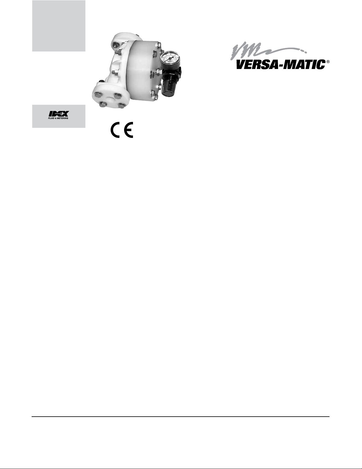
Model VDA05
Model VDA07
Model VDA10
Metallic and Non-Metallic
Surge Dampeners
Table of Contents
Principle of Operation ............................................................................ 1
Temperature Limitations ........................................................................1
Installation & Startup .............................................................................1
Service & Warranty ................................................................................ 1
Dimensions ............................................................................................ 2
Installation Guide ................................................................................... 3
Repair Parts List .................................................................................... 4
Repair Parts Drawing ............................................................................5
CE Declaration of Conformity - Machinery ............................................6
Versa-Matic • A Unit of IDEX Corporation • 800 N. Main St., Manseld, Ohio 44902 USA
vVDA050710sdsm-rev0512
Telephone (419) 526-7296 • Fax (419) 526-7289 • www.versamatic.com
©Copyright 2012 Versa-Matic. All rights reserved.
Page 2

Page 3
SERVICE AND OPERATING MANUAL
Model VDA05 ½" Surge Dampener
Model VDA07 ¾" Surge Dampener
Model VDA10 1" Surge Dampener
The Versa-Matic Surge Dampener reduces ow and pressure pulsation which is
characteristic of reciprocating pumps.
PRINCIPLE OF OPERATION
The surge dampener uses a exible virgin PTFE diaphragm to separate a liquid
chamber from a compressed air chamber. After the dampener is manually
charged with air, the diaphragm strokes at the same rate as the pump strokes.
This movement effectively "dampens" ow and pressure uctuations.
TEMPERATURE LIMITATIONS
Operating temperature limitations are as follows.
Material Minimum Temp. Maximum Temp.
PVDF 0°F/ -18°C 212°F / 100°C
Nylon 32°F/ 0°C 180°F / 82°C
Polypropylene 32°F/ 0°C 180°F / 82°C
Virgin PTFE -35°F/ -31°C 212°F / 100°C
Nitrile -10°F/ -23°C 190°F / 88°C
INSTALLATION & START-UP
Locate the unit in the discharge piping near the pump. The dampener will operate
in any position. However, when used with liquids that tend to settle out, the unit
should be installed at the top side of piping to provide easy discharge of foreign
solids by gravity.
Adjust the inlet air pressure to the dampener until the pump runs as smoothly
as possible. Watch the liquid discharging, or use a gauge, to detect pressure
uctuations. Then adjust pressure to the unit as needed.
IMPORTANT
Read these safety warnings
and instructions in this
manual completely, before
installation and start-up
is the responsibility of the purchaser to retain
this manual for reference. Failure to comply with
the recommendations stated in this manual will
damage the surge dampener, and void factory
warranty.
Maximum
operating pressure
is 100 psi (7 bar).
Limitation are
based upon mechanical stress only and may
be signicantly altered by pumping certain
chemicals. Consult engineering guides for
chemical compatibilities and temperature limits.
of the surge dampener. It
CAUTION
CAUTION
Before surge dampener
operation, inspect all
gasketed fasteners for
looseness caused by
loose fasteners to prevent leakage. Follow
recommended torques stated in this manual.
gasket creep. Re-torque
NOTE: Self-relieving regulator 020-039-000 will make these adjustments easier.
SERVICE
When service is required on the dampener, remove the 8 capscrews. The wetted
chamber can be removed from the unit and exposes the diaphragm. Remove the
diaphragm. When reassembling the wetted chamber onto the air chamber, use
a torque wrench set at 70 in/lbs. (7.9 Newton meters)
WARRANTY
This unit is guaranteed for a period of ve years against defective material and
workmanship.
vda050710sdsm-rev0512 Models VDA05, VDA07, VDA10 Page 1
Page 4

DA05
1/2 NPT (BSP)
DA07
THREADED PORT
1/2 NPT (BSP)
THREADED PORT
VDA07
3/4 NPT (BSP)
THREADED PORT
VDA05
Metallic and
Non-Metallic
3/4 NPT (BSP)
THREADED PORT
VDA10
Models VDA05, VDA07, VDA10 Page 2 vda050710sdsm-rev0512
Page 5

Available From
Available from
Versa-Matic
Warren Rupp, Inc.
1
Surge Dampener
Filter/Regulator
2
3
Lubricator
4
Air Dryer
INSTALLATION GUIDE
Top Discharge Ball Unit
CAUTION
The air exhaust should be
piped to an area for safe
disposition of the product
being pumped, in the event
of a diaphragm failure.
1
Surge
Dampener
Limited to
125 psi
4
2
vda050710sdsm-rev0512 Models VDA05, VDA07, VDA10 Page 3
3
Page 6

REPAIR PARTS LIST
Model VDA05 ½" Surge Dampener
Model VDA07 ¾" Surge Dampener
Model VDA10 1" Surge Dampener
ITEM PART TOTAL
NO. NUMBER DESCRIPTION RQD.
1 196-161-552 Chamber, Outer 1
196-161-520 Chamber, Outer 1
196-161-542 Chamber, Outer 1
196-171-110 Chamber, Outer (VDA05 Metallic only) 1
196-171-157 Chamber, Outer (VDA05 Metallic only) 1
2 360-099-360 Gasket, Spacer 1
3 334-103-552 Flange, Threaded ½" NPT (VDA05) 2
334-103-542 Flange, Threaded ½" NPT (VDA05) 2
334-103-600 Flange, Threaded ½" NPT (VDA05) 2
334-109-110 Flange, Threaded ½" NPT (Metallic VDA05 only) 2
334-109-150 Flange, Threaded ½" NPT (Metallic VDA05 only) 2
334-104-552 Flange, Threaded ¾" NPT (VDA07) 2
334-104-542 Flange, Threaded ¾" NPT (VDA07) 2
334-104-600 Flange, Threaded ¾" NPT (VDA07) 2
334-107-552 Flange, 1" ANSI (VDA10) 2
4 135-022-115 Bushing, Reducer 2
5 196-166-552 Chamber, Inner 1
6 720-058-600 Seal, Flange 2
720-063-600 Seal, Flange (Metallic VDA05 only) 2
7 286-097-600 Diaphragm 1
8 171-064-115 Capscrew Hex Flange 5/16 -18 x 1.50 8
171-064-308 Capscrew Hex Flange 5/16 -18 x 1.50 8
170-029-330 Capscrew, Hex Flange 5/16 x 1.50 (Metallic VDA05 only) 4
9 544-005-115 Nut 5/16 Hex Flange Nut 5/16-18 10
544-005-308 Nut 5/16 Hex Flange Nut 5/16-18 10
545.004-330 Hex Flange Nut (Metallic VDA05 only) 10
10 171-070-115 Capscrew Hex Flange 5/16 -18 x 3.00 6
171-070-308 Capscrew Hex Flange 5/16 -18 x 3.00 6
171-070-330 Capscrew, Hex Flange (Metallic VDA05 only) 2
11 171-069-115 Capscrew Hex Flange 5/16 -18 x 2.5 2
171-069-308 Capscrew Hex Flange 5/16 -18 x 2.5 2
171-069-330 Capscrew, Hex Flange (Metallic VDA05 only) 2
12 538-002-115 Nipple 1/8 NPT 1
13 020-039-000 Regulator W/Gauge 1
14 170-045-330 Capscrew Hex Flange (VDA05 Metallic Only) 5/16 -18 x 1.25 4
15 900-004-330 LockWasher (VDA05 Metallic Only) 14
16 901-038-115 Flat Washer (Non-Metallic Only) 2
Repair Parts shown in bold face (darker)
type are more likely to need replacement
after extended periods of normal use. They
are readily available from most Versa-Matic
distributors. The pump owner may prefer to
maintain a limited inventory of these parts
in his own stock to reduce repair downtime
to a minimum.
IMPORTANT: When ordering repair parts
always furnish pump model number, serial
number and type number.
MATERIAL CODES
The Last 3 Digits of Part Number
000... Assembly, sub-assembly; and some
purchased items
110... CF*M (316) Stainless Steel
115... 302/304 Stainless Steel
157... 380/383 Die Cast Aluminum
308... Stainless Steel; Black PTFE Coated
330... Zinc Plated Carbon Steel
360... Nitrile Rubber. Color coded: RED
520... Injection Molded PVDF, Natural Color,
542... Nylon
552... Polypropylene
600... Virgin PTFE
©Copyright 2011 Versa-Matic. All rights reserved.
Models VDA05, VDA07, VDA10 Page 4 vda050710sdsm-rev0512
Page 7

REPAIR PARTS DRAwING
14
16
10
Supplied with regulator
3
13
12
4
11
5
10
11
16
Nameplate location
2
* Diaphragms must be installed
as shownwith convolutions facing
7
*
the outer chamber.
DA10 only
1" ANSI fl ange
1
6
3
6
15
9
15
9
15
3
14
8
vda050710sdsm-rev0512 Models VDA05, VDA07, VDA10 Page 5
Page 8

Declaration of Conformity
Manufacturer:
®
Versa-Matic
Certifies that Air-Operated Double Diaphragm Pump Series:
Non-Metallic E Series, VTA Series Metallic Surge Suppressors and
VDA Non-Metallic Surge Dampeners comply with the European Community
Directive 2006/42/EC on Machinery, according to Annex VIII. This product
has used Harmonized Standard EN 809, Pumps and Pump Units
for Liquids - Common Safety Requirements, to verify conformance.
Signature of authorized person
, Warren Rupp, Inc., 800 N. Main Street, P.O. Box 1568,
Mansfield, Ohio, 44901-1568 USA
October 17, 2007
Date of issue
David Roseberry
Printed name of authorized person
Revision Level: C
Engineering Manager
Title
May 27, 2010
Date of revision
 Loading...