

Page 1
DATA SHEET, SERVICE & OPERATING MANUAL
DATA SHEET, SERVICE & OPERATING MANUAL
DATA SHEET, SERVICE & OPERATING MANUALDATA SHEET, SERVICE & OPERATING MANUAL
AIR OPERATED
AIR OPERATED
AIR OPERATED AIR OPERATED
DOUBLE DIAPHRAGM PUMP
DOUBLE DIAPHRAGM PUMP
DOUBLE DIAPHRAGM PUMPDOUBLE DIAPHRAGM PUMP
Full Flow
Full Flow
Full FlowFull Flow
High Pressure Series
High Pressure Series
High Pressure SeriesHigh Pressure Series
Table of Contents
Performance Curve 1
Dimensions 1
Engineering Data & Temperature limitations 2
Explanation of Pump Nomenclature 2
Principle of Pump Operation 3
Installation guide 3
Troubleshooting 4
Recycling 4
Important Safety Information 4
Warranty 5
Service 5
Air Valve Overhaul 5
Wet-side Overhaul 5
Parts List 6
Assembly Drawing 7
Technical Notes 8
Technical Notes 9
Service / Maintenance Log 10
HG-CF-1042 Rev. C - 03/28/03
Page 2
DATA SHEET, SERVICE & OPERATIN G MANUAL
DATA SHEET, SERVICE & OPERATIN G MANUAL
DATA SHEET, SERVICE & OPERATIN G MANUALDATA SHEET, SERVICE & OPERATIN G MANUAL
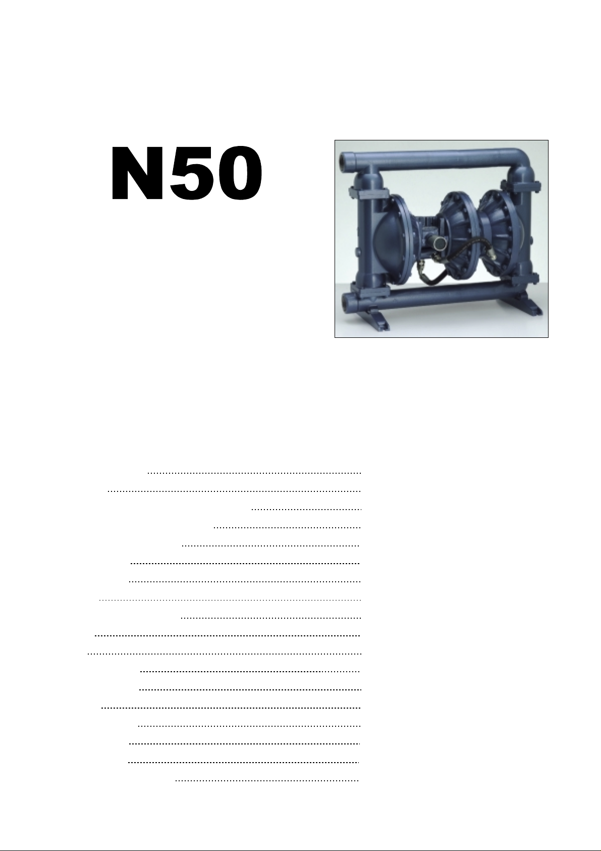
N50
N50
N50N50
AIR OPERATED
AIR OPERATED
AIR OPERATED AIR OPERATED
DOUBLE DIAPHRAGM PUMP
DOUBLE DIAPHRAGM PUMP
DOUBLE DIAPHRAGM PUMPDOUBLE DIAPHRAGM PUMP
Full Flow High Pressure Series
Full Flow High Pressure Series
Full Flow High Pressure SeriesFull Flow High Pressure Series
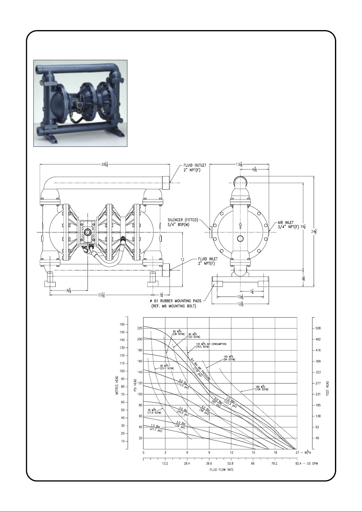
N50 Full Flow High Pressure Pump
Performance based on water at ambient temperature
HG-CF-1042 Rev. C - 03/28/03
Performance Curve
Page 1
Page 3
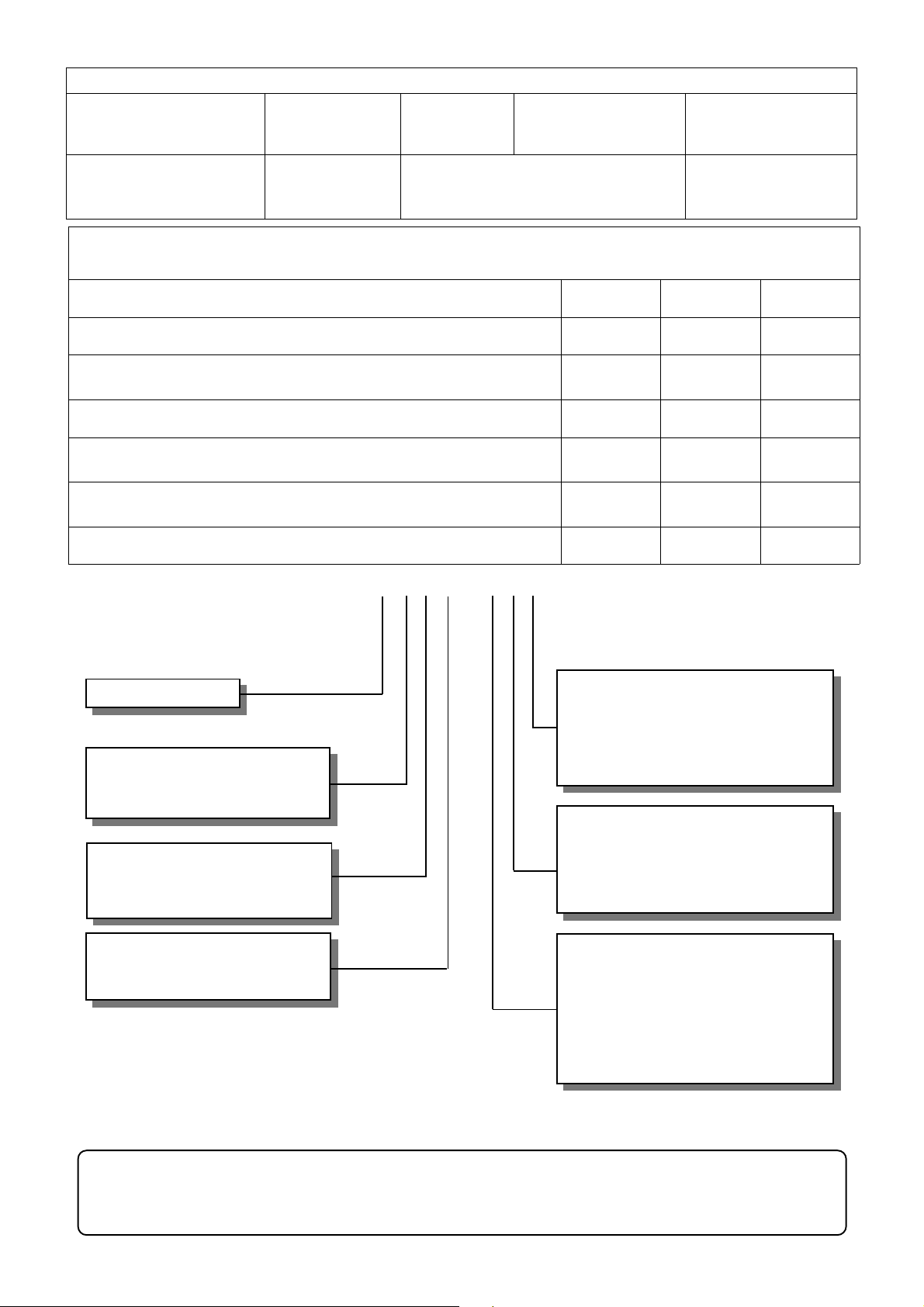
TECHNICAL DATA
FLUID CONNECTIONS CAPACITY MAX SOLIDS MAX DISCHARGE HEAD DISPLACEMENT/STROKE
2” NPT (F) 0 - 90 US Galls/Minute
(0 - 341 Liters/Minute)
1/4”
(6mm)
536 ft
(136 Meters)
0.5 US Gallons
(1.9 liters)
MAX. WORKING PRESSURE AIR INLET TEMPERATURE LI MITS PUMP WEIGHTS :-
16 Bar (232 psi) 3/4” NPT (F) Determined by Elastomers AA :- 65.5 Kg SA :- 75 Kg
Caution - Operating temperature limitations are as follows:
Materials
Buna-n - General purpose, oil resistant. Shows good solvent, oil, water and hydraulic fluid resistance. Should not
be used with highly polar solvents like acetone and MEK, ozone, chlorinated hydrocarbons and nitro hydrocarbons.
EPDM - Shows very good water and chemical resistance. Has poor resistance to oils and solvents, but is fair on
ketones and alcohols.
Neoprene - All purpose. Resistant to vegetable oil. Generally not affected by moderate chemicals, fats greases
and many oils and solvents. Generally attacked by strong oxidising acids, ketones, esters, nitro hydro carbons and
chlorinated aromatic hydrocarbons.
Santoprene® - Injection moulded thermoplastic elastomer with no fabric layer. Long mechanical flex life.
Excellent abrasion resistance.
Virgin PTFE - Chemically inert, virtually impervious. Very few chemicals are known to react chemically with
PTFE : molten alkali metals, turbulent liquid or gaseous fluorine and a few fluoro-chemicals such as chlorine
trifluoride or oxygen difluoride which readily liberate free fluorine at elevated temperatures.
Viton® - Shows good resistance to a wide range of oils and solvents : especially all alphatic, aromatic and
halogenated hydrocarbons, acids, animal and vegetable oils. Hot water or aqueous solutions(over 700F) will attack
Viton®.
Polypropylene - High strength, light weight, corrosion resistant polyolefin which easily withstands most
chemicals, with no known solvent at room temperature.
TYPICAL CODE = N2B. S A. W 3. N N S
SS :- ??? Kg
Operating Temperatures
Maximum Minimum Optimum
176oF
o
C
80
212oF
o
100
212oF
o
100
212oF
o
100
356oF
o
180
356oF
o
180
158oF
o
C
70
C
C
C
C
C
-18oF
o
-28
-11oF
o
-24
-4oF
o
-20
-10oF
o
-23
32oF
o
C
0
0oF
o
-18
-40oF
o
-40
C
C
C
C
C
C
50o to 140oF
o
to 60oC
10
50o to 212oF
o
to 100oC
10
50o to 130oF
o
10
to 54oC
50o to 212oF
o
to 100oC
10
50o to 212oF
o
to 100oC
10
75o to 212oF
o
to 100oC
24
50o to 140oF
o
to 60oC
10
MODEL - N50
WETTED COMPONENTS
A : ALUMINIUM
S : 316L STAINLESS STEEL
NON - WETTED COMPONENTS
A : ALUMINIUM
S : 316L STAINLESS STEEL
VALVE TYPE
B : BALL
W : WEIGHT E D BALL
This pump should be used in accordance with the requirements of the Health and Safety at Work Act 1974.
All business conducted subject to Blagdon Pump. Terms and Conditions of Sale, available on request.
VALVE SEATS
B : BUNA-N T : PTFE
E : EPDM V : VITON
N : NEOPRENE A : ALUMINIUM
S : STAINLESS STE EL
VALVE BALLS
B : BUNA-N T : PTFE
E : EPDM V : VITON
N : NEO PRENE
S : STAINLESS STE EL
DIAPHRAGMS
B : BUNA-N T : PTFE
E : EPDM V : VITON
H : POLYESTER (HYTREL)
N : NEO PRENE
P : POLYURETHANE
R : SANTOPRENE
O : ONE-PIECE PTFE
IMPORTANT
BLAGDON PUMP
BLAGDON PUMP
BLAGDON PUMPBLAGDON PUMP
HG-CF-1042 Rev. C - 03/28/03
A Unit of IDEX Corporation
6017 ENTERPRISE DRIVE, EXPORT,
PENNSYLVANIA 15632-8969, USA.
TEL. : (1) 724-327-7867 FAX. : (1) 724-733-4786
Web Site : www.blagdonpump.com
E-Mail : sales@blagdonpump.com
Page 2
Page 4
PRINCIPLE OF PUMP
OPERATION
This ball type c heck valve p ump is powered b y
compressed air and is a 2:1 ratio design. The
inner side of one diaphragm chamber is alternately pressurised while simultaneously exhausting the other inner chamber. This causes
the diaphra gms, which a re connected b y a common rod secured by plates to the centers of the
diaphragms, to move in a reciprocating action.
(As one diaphragm performs a discharge stroke
the other diaphragm is pulled to perform the
suction stroke in the opposite chamber.) Air
pressure is app lied over the entir e inner surface
of the diaphragm while liquid is discharged
from the opposite side of the diaphragm. The
diaphragm operates in a balanced condition
during the discharge stroke which allows the
pump to be operated at discharge heads of over
500 feet (152 meters) of water.
For maximum diaphragm life, keep the pump as
close to the liquid being pumped as possible.
Positive suction head in excess of 10 feet of
liquid (3.048 meters) may require a back pressure regulating device to maximize diaphragm
life.
Alternate pressurising and exhausting of the
diaphragm chamber is performed by an externally mounted, pilot operated, 2 way type
distibuti on valve. When the spool sh ifts to one
end of the valve block body, inlet pressure is
applied to one chamber and the other diaphragm
chamber exha usts. When th e spool shift s to the
opposite end of the valve body, the pressure to
the chambers is reversed. This alternating move-
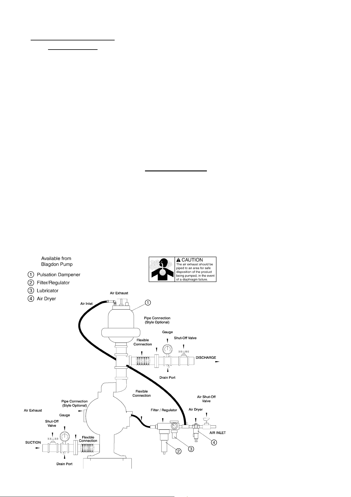
Installation Guide
Fig. 1
ment of the spool inside the valve body is controlled by a pilot air pressure signal held against
the diaphragm connecting rod, between seals in
the diaphragm shaft bushes. This signal is released, triggering the movement of the spool,
when pilot holes in the diaphragm connecting
rod align with the held pilot signal, sending the
signal to exhaust, which in-turn causes a pressure imbalance around the spool, sending it to
the opposite en d of the valve b ody. This si mutaneously sends inlet pressure to the opposite
chamber.
The chambers are connected with manifolds
with a suction and discharge check valve for
each chamber, maintaining flow in one direction
through the pump. The 2:1 ratio discharge pressure is generated by simultaneously delivering
air inlet pressure to alternate sides of a central
air diaphragm, the chambers either side of this
central diaphragm are pressurised and exhausted
in conjunction wi th the main diaphragm chambers.
INSTALLATION
The typical installation shown in FIG. 1 is only a
guide to selecting and installing system
components. Your installation will depend on
the type of fluid being pumped and your
application needs. To reduce the risk of serious
bodily injury and damage to property, never use
fluids in this pump which are not compatible
with the wetted components. Contact your local
distributor or the manufacturer for system design
assistance & compatibility if necessary.
Mount the pump in an upri ght position. Failur e
to ensure an upright pos ition may result in loss
of or poor priming ch aracteristics. Ensure the
pump is securely moun ted to avoid movement
and possible risk of bodily injury.
PRESSURE The pump delivers double the
pressure at the discharge outlet as the air
pressure applied at the air inlet.
NOTE: Pressure Regulator (H) should be
installed where air supply could exceed 125
psi.
SAFETY
Your BLAGDON PUMP is a high
performance unit capable of achieving
high output s at high efficien cies. However, as
is common with pneumatic equipment, the
pump efficienc ies is reliant upon the air being
clean, dry and filtered. Failure to comply with
these requirements may lead to loss of
performance and reduced component life and in
extreme cases, permanent damage to the pump.
To avoid leaks, ensure that all fluid connections
are tight. The use of PTFE thread tape co rrectly
applied should be used to ensure 100%
leakproof connections. Failure to ensure
100% sealability of the suction connection
could adversely affect suction performance.
If you are pumping hazardous fluids, or
operating the pump in an enclosed area, it is
essential that the exhaust from the pump is
piped away to a safe location. When pumping
hazardous fluids the above instructions must be
adhered to in order to ensure safe operating
procedures. (Under certain operating
conditions the failure of internal components
can lead to the pumped fluid being exhausted
via the pump exh aust outlet).
WARNING
NEVER place your hands over or near the
pump suction inlet. Powerful suction could
cause serious bodily injury.
FLUSH THE PUMP This pump was tested
with water containing an oil-based rust
inhibitor. If thi s solution could c ontaminate or
react with the fluid you are pumping, flush the
pump thoroughly with a solvent/detergent to
clean internal components. The solvent/
detergent must be compatible with the pump
materials of con struct ion. Ca re shou ld b e taken
to flush the pump each time it is disassembled
for maintenance or repair.
CAUTION Ensure that only the
recommended grade of lubricating oil is used.
BLAGDON PUMPS require an SAE 10
lubricating oi l. Other grades of oil may ca use
the Air Logic Syst em to operate intermi ttently,
thereby causin g a loss of output and failure to
operate.
If the pump accelerates or is running too fast
due to a lack of fluid, then stop it immediately
by shutting off the air supp ly. A dry pump will
accelerate to a high speed causing wear to
elastomers.
If the fluid you are pumping tends to dry up or
set when it is no t moving, then flush th e pump
as often as necessary to prevent the fluid from
drying in the pump. Drain the pump thoroughly
before storing.
If feasible, invert pump to allow any fluid to
drain from the no n- r eturn valves
.
HG-CF-1042 Rev. C - 03/28/03
Page 3
Page 5

TROUBLE SHOOTING GUIDE
NOTE :- Check all solutions before dismantling the pump.
PROBLEM CAUSE SOLUTION
Pump will not start Air valve assembly malfunction/Siezure
Obstructed fluid line.
Obstructed diaphragm chamber.
Diaphragm failure causing fluid & excessive air to be
expelled through the exhaust.
Diaphragm seal failure.
Air valve system malfunction.
Air connected to exhaust.
Erratic flow Diaphragm failure on one side.
Valve ball not seating.
Suction leakage.
Diaphragm failure causing fluid & excessive air to be
expelled through the exhaust.
Diaphragm seal failure.
Air valve system malfunction.
Pump strokes but will not
discharge
Excessive suction lift.
Suction line leakage.
Valve ball not seating correctly or damaged.
Suction line or strainer clogged.
Diaphragm failure.
Fluid discharged from air
exhaust
Diaphragm Failure.
Loose frontplate.
Intermitten t str oke rate Over lubrication
Diaphragm shaft seal failure.
Air valve system malfunction.
Valve ball not seating / partially obstructed.
Check carrier for freedom of movement. Clean, oil & replace.
Clean line or increase line size.
Remove obstruction.
Replace diaphragm.
Replace shaft seals.
Check all seals in valve chest assembly.
Re-connect to air inlet.
Replace diaphragm.
Check and remove obstruction.
Check and correct.
Replace diaphragm.
Replace shaft seals.
Check all seals in valve chest assembly.
Shorten suction line.
Check and correct.
Check and remove obstruction / replace.
Clear.
Replace diaphragm.
Replace diaphragm.
Re-Torque to manual specifications.
Shut-down pump. Remove air connection
into pump & introduce a small quantity of degreasing agent into air valve and replace
line. Run pump until clear.
Replace seals.
Check all seals in valve chest assembly.
Clear obstruction.
WARNING!
Read these safety warnings
and instructions in this m anual
and start-up of the pump. It is the
responsibility of the purchaser to retain this
manual for refere nce. Failur e to c omply wi th
the recommendatio ns stated in this m anual
will damage the pump, and void factory
warranty.
completely, before installation
WARNING!
Before doing any
maintenance on the pum p, be
completely vented from the pump, suction,
discharge, piping, and all other openings
and connections. Be ce rtain th e air s uppl y is
locked out or made non- operational, s o that
it cannot be started whil e work is being done
on the pump. Be certain that approved eye
protection and protec tive clothing are worn
all times in the vicinit y of the pump. Failure
to follow these recom mendati ons ma y result
in serious injury or death.
certain all pressure is
WARNING!
Airborne particles and loud
noise hazards. Wear ear and
eye protection.
WARNING!
Before maintenance or repair,
shut off the com-pressed air
disconnect the air li ne from the pump. The
discharge line may be pre ssuri zed and mus t
be bled of its pressure.
line, bleed the pressure, and
WARNING!
Take action to prevent static
sparking. Fire or explosion
handling flammable liquids. The pump,
piping, valves, containers or other
miscellaneous equipment must be
grounded.
can result, especially when
IMPORTANT!
This pump is pressurized
internally with air pressure
make certain that all bolting is in good
condition and that all of t he cor rect bol t ing is
reinstalled during ass em bly.
during operation. Always
WARNING!
When used for toxic or
aggressive fluids, the pump
clean prior to disassembly.
should always be flushed
WARNING!
In the event of diaphragm
rupture, pumped m aterial may
and be discharged into the atmosphere. If
pumping a product which is hazardous or
toxic, the air exhaust must be piped to an
appropriate area for safe disp osi tio n.
enter the air end of t he pump,
CAUTION!
Before pump operation, inspect all gasketed fasteners
ket creep. Re-torque loose fasteners to
prevent leakage. Follow recommended
torques stated in this manual.
for looseness caus ed by gas-
RECYCLING
Many components of
KREMLIN air ope rated do uble
diaphragm pumps are made
encourage pump use rs to recycle worn out
parts and pumps whenever possible, after
any hazardous pumped fluids are
thoroughly flushed.
of recyclable materials. We
HG-CF-1042 Rev. C - 03/28/03
Page 4
Page 6

IMPORTANT!
Read these instructions
completely, before
installation and start-up. It
is the responsibility of the purchaser t o
retain this manual for reference.
Failure to comply with the
recommendations stated in this
manual will damage the pump, and
void factory warranty.
SERVICE
The following sections give a general
overview on how to service all
models of BLAGDON Diaphragm
Pumps. For details on individual part
numbers, quantities, materials, etc.,
please consult the parts list supplied
with the pump.
NOTE : Before commencing
any service or maintenance work
on the pump, ensure that the air
supply has been disconnected or
isolated.
AIR VALVE SYSTEMS
PNEUMATIC TYPE Remove the 4
screws securing the valve block to
the valve chest, together with any
associated gaskets or seals.
Remove slide valve plate & slide
valve from the valve block assembly.
Clean all parts thoroughly and
inspect for excessive wear, replacing
where necessary.
The slide valve and valve plate
contact faces should be flat and free
from scratches. A light polishing on a
flat surface with a fine abrasive paper
will remove most scratches.
If excessive wear is suspected in the
valve block bore or valve carrier,
remove the valve block plugs and
withdraw the valve carrier. Check
valve block plug o-rings for wear or
attack & replace where required.
Clean the valve carrier & valve block
bore with white spirits to remove any
oil films.
NOTE : The nominal
diametrical clearance between the
valve carrier and the valve block
block bore should be 0.002” -
0.0035”. A clearance in excess of
this will cause the valve system to
run erratically.
Apply a light grease to the valve
block plug O-rings when reassembling into the valve block bore.
Any damage to the O-ring may cause
the valve system to malfunction.
Re-assemble the valve block
assembly & re-torque in accordance
to the settings shown in the parts list.
In the event of a complete air-side
overhaul, the pump should be disassembled down to the centre
section assembly as described later
in the “Wet-Side Overhaul” section.
With the valve block assembly
dismantled, remove the inner covers
where appropriate.
A careful note of the position of all
related seals and gaskets should be
made to facilitate re-assembly.
Remove diaphragm shaft bushes,
where appropriate, and check all
seals and ‘O’ rings for wear or
damage. If worn, replace
immediately.
NOTE:- The integrity of the
diaphragm shaft seals is essential
for the correct functioning of all
pneumatically actuated valve
systems.
Check the diaphragm shaft for
excessive wear as this will result in
premature seal failure. Replace as
required. Lubricate all components
and re-assemble as detailed above,
in reverse order. Ensure the correct
position of all components detailed in
all sectional assembly drawing s.
WET-SIDE OVERHAUL
REPLACING BALL VALVES
Remove discharge manifold from
pump assembly together with
associated valve balls, seats and ‘O’
rings.
NOTE :- The orientation of the
valve seat relative to the valve ball
should be noted as incorrect
positioning may result in a
performance loss.
Turn pump through 180
the suction manifold. Clean and
inspect the components. Check for
any wear or damage and replace as
required.
NOTE :- Ball or valve seat wear
may result in loss of performance
and suction lift.
Re-assemble the valve balls/seats
and ensure manifolds are adequately
torqued to the settings shown in the
parts list.
o
and remove
REPLACING DIAPHRAGMS
Remove both suction and discharge
manifolds as detailed in the previous
section, removing all ball valves,
seats and ‘O’ rings.
Loosen and remove both outer
covers from the pump assembly.
The orientation of the covers should
be noted so as to facilitate reassembly.
Holding one of the frontplates in a
vice, (‘soft jaws’ should be fitted), or
with an adjustable spanner, loosen
and remove the frontplate from the
opposite end. Remove the
diaphragm, backplate and bumpstop
from diaphragm shaft.
Carefully withdraw the diaphragm
shaft from the centre section and
hold the free end in a vice, holding
between the flats machined on the
end. Loosen and remove the
frontplate and remove the diaphragm
together with backplate and
bumpstop (where fitted).
NOTE :- Care should be taken with
all plastic, coated and hygienic
pumps, so that the surface of the
frontplate is not damaged.
Thoroughly clean all parts and check
for wear, damage, swelling, cracking,
delamination and chemical attack.
Replace components where required.
NOTE :- Rubber diaphragms
should be replaced if they are
worn to such an extent that the
fabric re-enforcing is evident on
the surface of the diaphragm.
For pumps fitted with PTFE
diaphragms, a light coating of grease
should be applied to the back-up
diaphragm prior to re-assembly.
Before re-assembly, it is advisable to
check the condition of the diaphragm
shaft seal/’O’ rings for wear or attack.
If either is evident, it is recommended
that they be replaced.
Assemble the diaphragms onto the
shaft in a reverse sequence to their
removal. Care should be taken as to
the orientation of the diaphragm
relative to the front and back plates.
All diaphragms have “AIR SIDE”
molded onto one side. The backplate
must be fitted adjacent to the AIR
SIDE of the diaphragm.
HG-CF-1042 Rev. C - 03/28/03
Page 5
Page 7

PARTS LIST
HG-CF-1042 Rev. C - 03/28/03
REF
PART NUMBER DESCRIPTION
QTY
No.
ALUMINUM /
COMMON PARTS
1 D172 D314 SOCKET CAP SCREW M8 x 20
2 C013 C173 WASHER M8
3 1B024 50-116 BASE LEG
4 50-234 50-236 SUCTION MANIFOLD - NPT
5 SEE TABLE O-RING (METALLIC SEATS ONLY)
6 SEE TABLE VALVE SEAT
7 SEE TABLE O-RING
8 50-082 OUTER COVER RING
9 50-005 50-222 FRONTPLATE
10 50-198 50-272 BUMPSTOP
11 1B021 BACKPLATE
12 50-052 OUTER COVER
13 SEE TABLE DIAPHRAGM
14 SEE TABLE O-RING
15 50-081 OUTER COVER RING
16 SEE TABLE CHECK VALVE
17 50-235 50-237 DISCHARGE MANIFOLD - NPT
18 50-194 50-268 INNER COVER
19 G112 O-RING
20 D028 SOCKET CAP SCREW M8 x 25
21 50-193 50-269 VALVE CHEST
22 50-197 BACKPLATE
23 1B026 1B087 INNER COVER - AIR CHAMBER
24 AP50-45 GREASE NIPPLE
25 B027 B147 NUT M10
26 C026 C146 WASHER M10
27 A063 A152 BOLT M10 x 40
28 A006 A181 BOLT M8 x 40
29 C013 C173 WASHER M8
30 B003 B043 NUT M8
31 1B114 SILENCER
32 1B025 BASE PAD
33 A041 A042 BOLT M8 x 30
34 C126 C126 WASHER M8
Page 6
35 1B034 BASE LEG CAP
36 50-200 LOCK-NUT
37 50-210 DIAPHRAGM - AIR CHAMBER
38 50-199 THRUST WASHER
ST. STEEL
4
4
2
1
4
4
4
2
2
2
2
2
2
2
2
4
1
2
4
24
1
2
2
1
36
36
36
16
32
16
1
4
4
4
4
2
1
1
PARTS LIST - cont
REF
PART NUMBER DESCRIPTION
No.
ALUMINUM /
COMMON PARTS
39 50-204 50-270 AIR HOSE ASSEMBLY
40 50-205 50-271 HEX. ADAPTOR
41 50-201 50-267 AIR DISTRIBUTION MANIFOLD
42 G270 O-RING
43 50-195 DIAPHRAGM SHAFT
44 50-196 DIAPHRAGM SHAFT BUSH
45 50-206 DIAPHRAGM SHAFT SEAL
46 G167 O-RING
47 1B032 NAMEPLATE
48 K076 HAMMERDRIVE SCREW
49 50-207 DIAPHRAGM SHAFT SEAL
50 50-203 SPACER BUSH
51 50-202 50-266 SPACER
52 G057 O-RING
53 1B015 BUMPSTOP
54 G205 O-RING
55 D177 D322 SOCKET CAP SCREW M4 x 10
56 G206 O-RING
57 G207
58 1C021 VALVE BLOCK PLUG
59 H125 CIRCLIP
60 G130 O-RING
61 C173 C173 WASHER
62 D309 D309 SOCKET CAP SCREW M8 x 30
63 1B215 VALVE BLOCK - NPT
64 1B135 FILTER
65 1B124 VALVE CARRIER
66 1B125
67 1B126
68 D311
69 1B137
70 1B123
71 1B001 DIAPHRAGM SUPPORT
72 1B039 DIAPHRAGM
ST. STEEL
O-RING (ALL ST. STEEL MODELS :- 4 OFF)
SLIDE VALVE
SLIDE VALVE PLATE
SOCKET C’SUNK SCREW (SS MODELS ONLY)
TRANSITION PLATE (SS MODELS ONLY)
PORT SEAL (ALL ST. STEEL MODELS - 2 OFF)
- These items are available in a recommended spares kit. Please refer to your local stockist /
distributor for details.
- These items are available in a recommended spares kit - SA10406 - Air Side Kit.
All Stainless Steel models - Air Side Kit :- SA10481
1
QTY
2
4
1
2
1
2
6
4
1
2
2
1
1
2
2
2
2
1
2
2
2
2
4
4
1
1
1
1
1
4
1
2
2
Page 8

HG-CF-1042 Rev. C - 03/28/03
Page 7
Sectional General Assembly :- N2B Full Flow 2:1 Metallic Pump
Refer to pages 6 & 8 : Parts List table for item Ref. Nos.
Page 9

TECHNICAL NOTES :-
ELASTOMER TABLE
REF
No.
5 O-RING G426 G416 4
6 VALVE SEAT 50-045 - 4
7 O-RING G458 G461 4
13 DIAPHRAGM 1B001 50-233 SEE 69 & 70 2
16 CHECK VALVE - 1B053 4
16 CHECK VALVE (WTD) 1B027 - 4
14 O-RING G424 G417 2
REF
No.
6 VALVE SEAT 50-091 4
13 DIAPHRAGM - 2
16 VALVE BALL - 4
DESCRIPTION
DESCRIPTION
NEOPRENE SANTOPRENE® PTFE QTY
ELASTOMER TABLE - cont’d
STAINLESS
STEEL
QTY
Manifold (41)
HG-CF-1042 Rev. C - 03/28/03
Air Hose connections :When assembling Air Hoses (item 39) ensure that inlet &
outlet connections on Air Dist. Man. (item 41) and spacer
(item 51) are on same side of pump.
Spacer (51)
Page 8
Page 10

TECHNICAL NOTES :-
10
9
Locknuts (36)
Diaphragm Shaft
Diaphragm
Removal of Diaphragm Shaft :- Af ter first removing manifolds and air-hoses, remove both outer covers (12), followed by frontplates (9),
diaphragms (13), backplates (11) and bumpstops (10). Remove air-chamber assy, by removing nuts &
bolts as at (26) & (27). This allows access to locknuts (36) to remove air diaphragm, backplates & thrust
washer (37), (22) & (38). Diaphragm Shaft can now be removed. Assembly is reverse of removal,
applying a small amount of Loctite grade 242 to locknuts prior to refitting air-chamber ass y.
Backplates
Air Chamber
11
13
12
NOTES :-
HG-CF-1042 Rev. C - 03/28/03
Page 9
Page 11

Service / Maintenance Log
Date Details Completed
Contact Phone / Fax No.
BLAGDON PUMP
BLAGDON PUMP
BLAGDON PUMPBLAGDON PUMP
HG-CF-1042 Rev. C - 03/28/03
A Unit of IDEX Corporation
Contact Information
6017 ENTERPRISE DRIVE, EXPORT,
PENNSYLVANIA 15632-8969, USA.
TEL. : (1) 724-327-7867 FAX. : (1) 724-733-4786
Web Site : www.blagdonpump.com
E-Mail : sales@blagdonpump.com
Page 10
Page 12

HG-CF-1042 Rev. C - 03/28/03
 Loading...