

Page 1
Zebra
Bus, SPI and I2C
Yocto Linux
User Guide
REV. April 2018
(VL-EPC-2701)
Arm* i.MX6 Single Board Computer
with Gigabit Ethernet, V ideo, USB,
SATA, Serial I/O, Digital I/O, CAN
Page 2

WWW.VERSALOGIC.COM
12100 SW Tualatin Road
Tualatin, OR 97062
-7341
(503) 747-2261
Fax (971) 224
-4708
Copyright © 2018 VersaLogic Corp. All rights reserved.
Notice:
Although every effort has been made to ensure this document is error
-free, VersaLogic makes no representations or
warranties with respect to this product and specifically disclaims any implied warranties of merchantability or fitness
for any particular purpose.
VersaLogic reserves the right to
revise this product and associated documentation at any time without obligation to
notify anyone of such changes.
* Other names and brands may be claimed as the property of others.
ii Zebra (VL-EPC-2701) Yocto Linux User Guide
Page 3

Product Release Notes
Rev 1.0
Initial release for the Rev 1.0 board
Support Page
The Zebra Support Page
contains additional information and resources for this product including:
Operating system information and software drivers
Data sheets and manufacturers’ links for chips used in this product
U-Boot information and upgrades
VersaTech KnowledgeBase
The VersaTech KnowledgeBase contains useful technical information about VersaLogic products,
along with product advisories.
Customer Support
If you are unable to solve a problem after reading this manual, visiting the product support page,
or searching the KnowledgeBase, contact VersaLogic Technical Support at (503) 747-2261.
VersaLogic support engineers are also available via e-mail at Support@VersaLogic.com.
Repair Service
If your product requires service, you must obtain a Returned Material Authorization (RMA) number
by calling 503-747-2261. Be ready to provide the following information:
Your name, the name of your company, your phone number, and e-mail address
The name of a technician or engineer that can be contacted if any questions arise
The quantity of items being returned
The model and serial number (barcode) of each item
A detailed description of the problem
Steps you have taken to resolve or recreate the problem
The return shipping address
Warranty Repair: All parts and labor charges are covered, including return shipping charges for
UPS Ground delivery to United States addresses.
Non-warranty Repair: All approved non-warranty repairs are subject to diagnosis and labor
charges, parts charges and return shipping fees. Specify the shipping method you prefer and
provide a purchase order number for invoicing the repair.
Note: Mark the RMA number clearly on the outside of the box before returning.
Zebra (VL-EPC-2701) Yocto Linux User Guide iii
Page 4

Contents
Introduction ................................................................................................................... 6
Quick Start ..................................................................................................................... 7
Setting up Zebra for the First Time .................................................................................... 7
Booting up Zebra for the First Time ................................................................................... 8
Basic Zebra Features and Commands ....................................................................... 10
USB Support ..................................................................................................................... 10
Video Support ................................................................................................................... 10
MikroBUS Compatible Socket ......................................................................................... 10
Storage Support ................................................................................................................ 10
Multimedia Support .......................................................................................................... 10
Multimedia Playback ........................................................................................... 10
Audio Recording ............................................................................................................... 11
Setting up the Development Host .............................................................................. 13
Host Packages ................................................................................................................... 13
Setting up the Repo Utility ............................................................................................... 14
Yocto Project Setup .................................................................................................... 15
Building the Zebra Image ............................................................................................ 17
Setting up the Build Configurations ................................................................................. 17
Patching the Build Configuration ..................................................................................... 18
Creating the Target Image ................................................................................................ 19
Deploying the Image to Zebra .................................................................................... 20
Deploying the MicroSD Card ........................................................................................... 20
Booting from the Network ................................................................................................ 20
Configuring the Host PC ..................................................................................... 20
Configuring U-Boot Environmental Variables .................................................... 21
Deploying to eMMC ............................................................................................ 23
Creating a Simple Application .................................................................................... 25
Standalone Application ..................................................................................................... 25
Adding the Application to the Image ................................................................................ 26
Customizing the Image ............................................................................................... 29
Adding or Removing Packages ......................................................................................... 29
Modifying Linux Kernel Configuration ........................................................................... 30
Updating U-Boot ............................................................................................................... 32
iv Zebra (VL-EPC-2701) Yocto Linux User Guide
Page 5

Advanced Features and Commands .......................................................................... 35
Sensors .............................................................................................................................. 35
CAN Network ................................................................................................................... 37
2
C Commands .................................................................................................................. 38
I
GPIO ................................................................................................................................. 39
References ................................................................................................................... 40
Figures
Figure 1. Major Components and Connectors ................................................................................................. 7
Figure 2. Booting the System .......................................................................................................................... 8
Figure 3. Login ................................................................................................................................................ 9
Figure 3. X11 Desktop .................................................................................................................................... 9
Figure 5. Op ening a Terminal ........................................................................................................................ 11
Figure 6. Alsamixer ....................................................................................................................................... 11
Figure 7. Stopping Auto Boot ....................................................................................................................... 21
Figure 8. Printenv .......................................................................................................................................... 22
Figure 9. Netboot ........................................................................................................................................... 23
Figure 10. Firefox Icon .................................................................................................................................. 29
Figure 11. K ernel Configuration GUI ........................................................................................................... 30
Figure 12. Device Drivers ............................................................................................................................. 31
Figure 13. Sony MemoryStick ....................................................................................................................... 32
Tables
Table 1. Image Details ................................................................................................................................... 19
Zebra (VL-EPC-2701) Yocto Linux User Guide v
Page 6

1
Introduction
The VersaLogic EPC-2701 Zebra is an ARM based Single Board Computer (SBC). It is consists
of a NXP i.MX6 ARM Cortex-A9 single or dual core processor and many standard components,
which will be described in more detail later. The single core version of Zebra is named “Solo,”
while the dual core version is “DualLite.” The recommended OS is Yocto Linux which is an opensource collaboration focused on embedded Linux OS development.
The purpose of this guide is to provide an overview of the Zebra product, as well as to help the
user to configure the system to boot for the first time. It also provides instructions on how to set up
a Yocto Linux development environment and to build the OS image, develop a simple application,
and deploy the OS and applications to the Zebra for execution.
However, this guide is not intended to provide significant amount of background information on
the NXP i.MX6 ARM Cortex-A9 processor or Yocto Linux. The commands used are intended as
examples; it is possible that there are also other Linux commands which will accomplish the same
results. The user is encouraged to follow the links in the reference section to learn more.
This guide assumes the user has basic knowledge of the Linux Operating System and is able to
obtain the necessary hardware and software required to complete the tasks outlined in this guide.
Note: The NXP i.MX6 ARM Cortex-A9 processor was originally made by Freescale. Freescale
was purchased by NXP, but much of the documentation still retains the name Freescale.
6 Zebra (VL-EPC-2701) Yocto Linux User Guide
Page 7

Quick Start
2
EPC-2701 Zebra Hardware Introduction
Detailed hardware description is available in the Zebra Hardware Reference Manual, but here is
some essential information required in order to quickly set up the board.
The following diagram shows the major components of a Zebra:
Figure 1. Major Components and Connectors
Quick Start
Setting up Zebra for the First Time
At a minimum, the following ports and devices should be connected before booting up Zebra for
the first time:
J1 – USBx2: connect USB mouse and keyboard to the USB ports. There are two options to do
this: Option one is to connect a USB hub to the bottom port, then connect both mouse and
keyboard to the hub. Option two is to set the top USB port to host mode and then use both on
board ports for mouse and keyboard.
Zebra (VL-EPC-2701) Yocto Linux User Guide 7
Page 8

Quick Start
J4 – MicroSD socket: install the MicroSD card in this socket. The space is tight so be careful not
to bend the pins or cause other damage.
J5 – Ethernet: connect network cable to the Ethernet port.
J6 – HDMI: connect a HDMI monitor to this port. If an HDMI monitor is not available, then a HDMI
to VGA adapter can connect to a VGA monitor. Note that the current limit for the HDMI 5V power
is 55mA, so when choosing an adapter make sure it draws less than that.
J15 – Power: connect the power cable from the adapter when instructed below, after all other
connections and jumper changes have been made.
J16 – COM1: connect the VL-CBR-0504 cable adapter for RS-232 serial port, and then connect
serial cable to a PC COM port. Use a terminal emulator such as PuTTY for console access to the
Zebra.
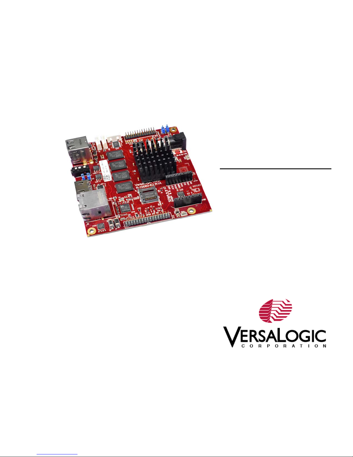
Booting up Zebra for the First Time
At this point, the Zebra is ready to boot up for the first time. Connect the power cable to the board
and watch the serial console and you should see the boot messages displayed. Please note that
instead of BIOS, Zebra uses a different boot loader called U-Boot. Unless auto boot is stopped by
pressing a key on the keyboard, U-Boot will load Yocto Linux from the microSD.
Figure 2. Booting the System
Once the system completes boot up, a login prompt will be displayed. Login as root; no password
is required.
8 Zebra (VL-EPC-2701) Yocto Linux User Guide
Page 9
Quick Start
Figure 3. Login
If a monitor is connected to the HDMI port, then a basic X11 Desktop as shown below will be
displayed on the monitor.
Figure 4. X11 Desktop
Zebra (VL-EPC-2701) Yocto Linux User Guide 9
Page 10

3
Assuming the Zebra is up and running with the OS provided by VersaLogic, this section describes
some of the built-in features on the Zebra board and Yocto Linux commands to utilize these
features.
USB Support
There are two USB ports on the Zebra that support standard USB 2.0 devices. The bottom USB
port is set to host mode, but the top USB OTG port is set to device mode by default. To change
the top USB port to host mode, install the V2 jumper per the Zebra Hardware Reference Manual.
Video Support
The Zebra has an integrated video controller that supports multiple video formats and provides an
HDMI V1.4 port, used with most standard monitors.
Basic Zebra Features and
Commands
MikroBUS Compatible Socket
The Zebra board includes a MikroBUS compatible socket that supports industry standard click
boards, which can provide expandability to support additional on-board I/O including I
serial lines. See the Zebra Hardware Reference Manual for socket pin support information.
Storage Support
Zebra supports onboard storage devices such as MicroSD and optional eMMC. The fdisk
command will list all the storage devices that are currently attached, as shown in the example
below.
root@imx6zebra:~# fdisk –l
…
[ This is the MicroSD card installed in the onboard socket. ]
/dev/mmcblk1p1 8192 24575 16384 8M c W95 FAT32 (LBA)
/dev/mmcblk1p2 24576 2834431 2809856 1.3G 83 Linux
Multimedia Support
Multimedia Playback
2
C, SPI and
GStreamer is the default multimedia framework on Linux OS, and gplay-1.0 is a command line
tool built on top of GStreamer that will test basic playback. MP3, MP4, WAV and AVI file formats
are verified on the Zebra.
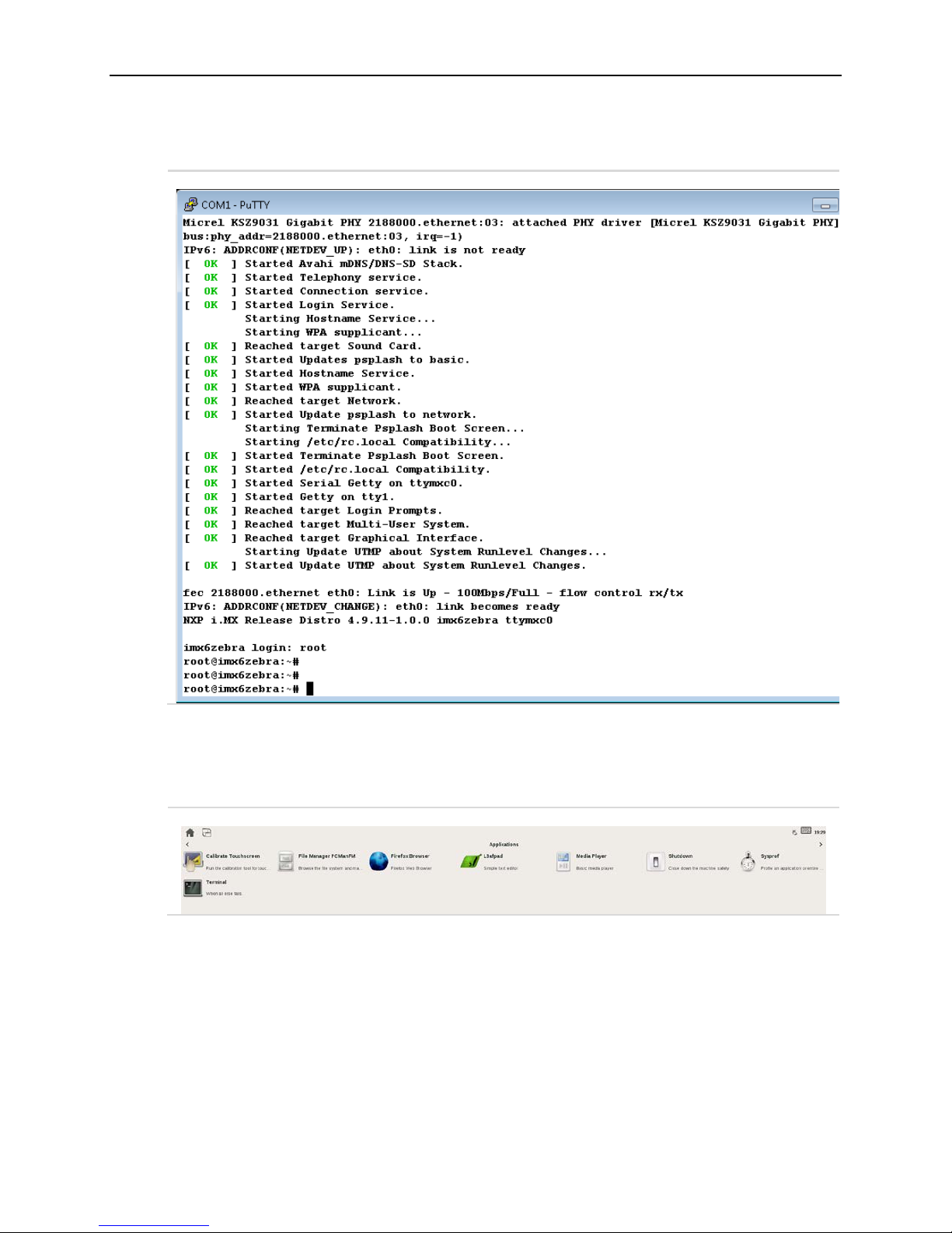
To play back a multimedia file, first make sure a speaker or headphone is properly connected to
the J10 – Audio port. Then open a terminal from the X11 Desktop as indicated below.
10 Zebra (VL-EPC-2701) Yocto Linux User Guide
Page 11
Basic Zebra Features and Commands
Figure 5. Opening a Terminal
Type the following command in the terminal window:
sh-4.3# gplay-1.0 <file name>
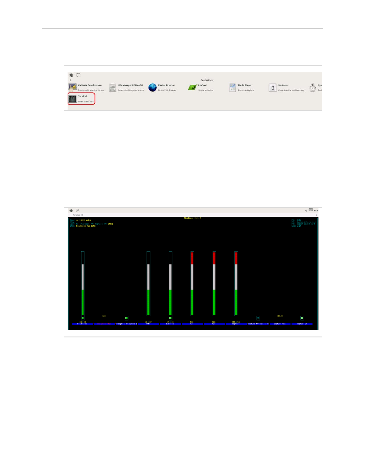
For MP3 and WAV files, command output should indicate that the sound track is playing. For MP4
and AVI files, a new window will also open displaying the vi deo. If there is no sound when
expected, first check the volume level by entering the alsamixer command in the terminal window
and adjust the headphone volume in the GUI using up or down arrow keys.
sh-4.3# alsamixer
Figure 6. Alsamixer
Audio Recording
To record audio on the Zebra, first connect a microphone or headset to the J10 – Audio port.
Adjust the recording level in alsamixer to high to ensure that sound can be captured. The level
can be adjusted downward later to achieve the best result.
Type the following command in the terminal window and speak into the microphone
sh-4.3# arecord -r 48000 -f S16_LE -c 2 -d 10 testrecord.wav
Recording automatically stops after 10 seconds. Play back the recording using the gplay-1.0
command:
sh-4.3# gplay-1.0 testrecord.wav
Zebra (VL-EPC-2701) Yocto Linux User Guide 11
Page 12

Basic Zebra Features and Commands
Note: Audio recording and playback are also possible through the J13 – User IO connector, but a
break-out cable is required in order to access line-in and line-out.
12 Zebra (VL-EPC-2701) Yocto Linux User Guide
Page 13

4
Setting up the Development Host
This chapter begins the discussion on how to build and customize the Yocto Linux OS to run on
Zebra.
A host PC or build server is required to setup the Yocto Linux development environment, which
will be used to create the Operating System that will run on the VersaLogic Zebra board.
There are a few minimum requirements for this system:
1. Hardware – a server machine will provide the best performance, but at least a mid-range
desktop PC is needed. Specifically, at least the following configuration:
A. 2 GHz dual core processor
B. 2 GB RAM (system memory)
C. 120 GB of free disk space is required in order to install the OS and required packages,
and to build the target image. However, more disk space is highly recommended as
multiple builds during typical development cycle can consume the disk space quickly.
D. V GA monitor capable of 1024x768 screen resolution
E. A CD/DVD drive or a USB port for the installer media
F. A static IP address is recommended but not required
G. Internet access to download additional required software
2. Operating System – the recommended OS for the host PC is Ubuntu 14.04, which is the
version currently supported for Zebra and has been verified by VersaLogic. If the user decides
to try a different version or Linux distribution, then it is up to the user to get the Yocto Linux
Project expected behavior on the host PC, as well as making sure the packages and utilities
described below are compatible and can be installed correctly.
Host Packages
A Yocto Linux Project build requires that some prerequisite software packages to be installed.
Please use the commands below to install these packages. Note that in Ubuntu, the command
sudo is typically used to execute other commands with root privileges.
1. Install essential Yocto Project host packages:
$ sudo apt-get install gawk wget git-core diffstat unzip texinfo gccmultilib build-essential chrpath socat libsdl1.2-dev
2. Install i.MX layers host packages for an Ubuntu 14.04 host:
$ sudo apt-get install libsdl1.2-dev xterm sed cvs subversion
coreutils texi2html docbook-utils python-pysqlite2 help2man make gcc
g++ desktop-file-utils libgl1-mesa-dev libglu1-mesa-dev mercurial
autoconf automake groff curl lzop asciidoc u-boot-tools
Zebra (VL-EPC-2701) Yocto Linux User Guide 13
Page 14

Setting up the Repo Utility
Git is a version control system for tracking changes in source code files and coordinating work on
those files among multiple developers. Repo is a tool built on top of Git that makes it easier to
manage projects that contain multiple repositories, which do not need to be on the same server.
Repo complements very well the layered nature of the Yocto Project, making it easier for users to
add their own layers to the BSP.
To install the “repo” utility, follow these steps:
1. Create a bin folder in the home directory.
$ mkdir ~/bin
$ curl http://commondatastorage.googleapis.com/git-repo-
downloads/repo > ~/bin/repo
$ sudo chmod a+x ~/bin/repo
2. Add the following line to the .bashrc file to ensure that the ~/bin folder is in your PATH
variable.
export PATH=~/bin:$PATH
3. Apply the new path to the current login session.
$ . ~/.bashrc
Setting up the Development Host
14 Zebra (VL-EPC-2701) Yocto Linux User Guide
Page 15

5
Yocto Project Setup
For Yocto Linux, files used to build an image are stored in layers. Layers contain different types of
customizations and come from different sources. Some of the files in a layer are called recipes.
Yocto Project recipes contain the mechanism to retrieve source code, and to build and package a
component. The following list shows some of the layers used to build the Zebra image:
VersaLogic release layer
• meta-versalogic
i.MX release layer
• meta-fsl-bsp-release
o meta-bsp - updates for meta-freescale, poky, and meta-openembedded layers
o meta-sdk - updates for meta-freescale-distros
Yocto Project community layers
• meta-freescale: provides support for the base and for i.MX ARM® reference boards.
• meta-freescale-3rdparty: provides support for 3rd party and partner boards.
• meta-freescale-distro: additional items to aid in development and exercise board
capabilities.
• meta-fsl-community-base: often renamed to base. Provides base configuration for FSL
Community BSP.
• meta-openembedded: Collection of layers for the OE-core universe. See
layers.openembedded.org/.
• poky: basic Yocto Project items in Poky. See the Poky README for details.
• meta-browser: provides several browsers.
• meta-qt5: provides Qt5.
In order to download all the necessary files, first make sure that Git is setup properly with the
commands below, which only need to be run once on the host PC.
$ git config --global user.name "Your Name"
(For example: git config --global user.name “John Doe”)
$ git config --global user.email "Your Email"
(For example: git config --global user.email “John.Doe@acme.com”)
$ git config --list
Zebra (VL-EPC-2701) Yocto Linux User Guide 15
Page 16

Interfaces and Connectors
The Freescale Yocto Project BSP Release directory contains a "sources" directory holding the
recipes used to build the image, as well as one or more build directories, and a set of scripts used
to set up the environment.
As an example, a directory called fsl-release-bsp is created for our project. Any name can be
used instead of it.
$ mkdir fsl-release-bsp
$ cd fsl-release-bsp
$ repo init -u git://git.freescale.com/imx/fsl-arm-yocto-bsp.git b imx-morty
$ repo sync
When this process completes, the source code is checked out into the directory fsl-releasebsp/sources. You can perform repo synchronization periodically with the command repo sync to
update to the latest code. If errors occur during repo initialization, try deleting the .repo directory
and running the repo initialization command again.
Last, download the VersaLogic release layer and recipes for the Zebra board:
$ cd sources
$ git clone git://github.com/versalogic/meta-versalogic.git -b
morty
The recipes used to build the Zebra image come from VersaLogic, the Yocto community and
NXP/Freescale. The Yocto Project layers are downloaded to the sources directory. This sets up
the recipes that are used to build the project. Follow the instructions below to download the
Freescale Yocto Project Community BSP recipe layers.
16 Zebra (VL-EPC-2701) Yocto Linux User Guide
Page 17

6
Building the Zebra Image
This section describes the necessary steps to building a Yocto Linux image that will run on the
VersaLogic Zebra board.
Setting up the Build Configurations
Freescale provides a script (fsl-setup-release.sh) that simplifies the build process. To use
the script, the name of the target machine needs to be specified, as well as the graphical backend
desired. The script sets up a build directory and pulls in necessary configuration files for the
specified machine and backend.
The syntax for the fsl-setup-release script is shown below:
$ DISTRO=<distro name> MACHINE=<machine name> source fsl-setuprelease.sh -b <build dir>
Whereas
• <distro name> specifies the graphical backend to be built, which configures the build
environment and it is stored in meta-fsl-bsp-release/imx/meta-
sdk/conf/distro.
Here is a list of available DISTRO configurations:
o fsl-imx-x11 - Only X11 graphics
o fsl-imx-wayland - Wayland weston graphics
o fsl-imx-xwayland - Wayland graphics and X11. X11 applications using EGL are
not supported
o fsl-imx-fb - Frame Buffer graphics - no X11 or Wayland
• <machine name> specifies the name of the target machine. For the Zebra, this should
be imx6zebra.
• <build dir> specifies the name of the build directory created by the fsl-setup-
release.sh script. It can be any name that the user chooses.
Below is an example of a complete command:
DISTRO=fsl-imx-x11 MACHINE=imx6zebra source fsl-setup-release.sh -b
testbuild
When the script runs, it prompts the user to accept an EULA. Once the EULA is accepted, the
acceptance is stored in local.conf inside each build directory and the EULA acceptance query
will no longer be displayed for that directory. After the script completes, the working directory is
changed to the one just created by the script, specified with the -b option. A conf directory is
created containing the files bblayers.conf and local.conf.
Keep in mind that this script needs to be executed every time a new terminal window is opened to
build the image, in order to set up the proper configurations for that window. The script also
refreshes both bblayers.conf and local.conf files. Therefore, it would be a good practice to
save a copy of these files under a different name, once they are modified so the same changes
will not have to be typed again.
Zebra (VL-EPC-2701) Yocto Linux User Guide 17
Page 18

Patching the Build Configuration
The <build dir>/conf/bblayers.conf file contains all the metalayers used in the
Freescale Yocto Project release. Edit this file to tell the build process where to find the VersaLogic
layer and how many CPU threads to run for the build. The number of threads depends on the
CPU hardware in the host PC. Utilizing the maximum number of supported threads will minimize
the length of time required to build the image.
To find out how many threads to use, first run the lscpu command:
$ sudo lscpu
Architecture: x86_64
CPU op-mode(s): 32-bit, 64-bit
Byte Order: Little Endian
CPU(s): 8
…
There are 8 CPU cores, so the same number of 8 threads should be used. Now add the following
two lines to bblayers.conf
${BSPDIR}/sources/meta-versalogic \
BB_NUMBER_THREADS = "8"
The resulting file should look like this:
$ cat bblayers.conf
POKY_BBLAYERS_CONF_VERSION = "2"
BBPATH = "${TOPDIR}"
BSPDIR := "${@os.path.abspath(os.path.dirname(d.getVar('FILE', True)) +
'/../..')}"
BBFILES ?= ""
BBLAYERS = " \
${BSPDIR}/sources/poky/meta \
${BSPDIR}/sources/poky/meta-poky \
\
${BSPDIR}/sources/meta-openembedded/meta-oe \
${BSPDIR}/sources/meta-openembedded/meta-multimedia \
\
${BSPDIR}/sources/meta-freescale \
${BSPDIR}/sources/meta-freescale-3rdparty \
${BSPDIR}/sources/meta-freescale-distro \
${BSPDIR}/sources/meta-versalogic \
"
##Freescale Yocto Project Release layer
BBLAYERS += " ${BSPDIR}/sources/meta-fsl-bsp-release/imx/meta-bsp "
BBLAYERS += " ${BSPDIR}/sources/meta-fsl-bsp-release/imx/meta-sdk "
BBLAYERS += " ${BSPDIR}/sources/meta-browser "
BBLAYERS += " ${BSPDIR}/sources/meta-openembedded/meta-gnome "
BBLAYERS += " ${BSPDIR}/sources/meta-openembedded/meta-networking "
BBLAYERS += " ${BSPDIR}/sources/meta-openembedded/meta-python "
BBLAYERS += " ${BSPDIR}/sources/meta-openembedded/meta-filesystems "
BBLAYERS += " ${BSPDIR}/sources/meta-qt5 "
BBLAYERS += " ${BSPDIR}/sources/meta-openembedded/meta-xfce "
BB_NUMBER_THREADS = "8"
Building the Zebra Image
18 Zebra (VL-EPC-2701) Yocto Linux User Guide
Page 19

Building the Zebra Image
Image Name
Target
Provided by Layer
core-image-minimal
A small image that only allows a device to boot.
poky
core-image-base
A console-only image that fully supports the target
device hardware.
poky
core-image-sato
An image with Sato, a mobile environment and visual
terminal, an editor and a file manager.
poky
fsl-image-machine-
test
An FSL Community i.MX core image with console
environment - no GUI interface.
meta-freescale-distro
fsl-image-validationimx
Builds an i.MX image with a GUI without any Qt content.
meta-fsl-bsprelease/imx/meta-sdk
fsl-image-validation-
Builds an opensource Qt 5 image. These images are
6UltraLiteLite or i.MX 7Dual.
meta-fsl-bsp-
Creating the Target Image
The Yocto Project provides some images available on different layers. Poky provides some
images, meta-fsl-arm and meta-fsl-demos provide others, additional image recipes are
provided in the meta-fsl-bsp-release layer. The following table lists various key images,
their contents, and the layers that provide the image recipes.
Table 1. Image Details
style for mobile devices. The image supports X11 with a
Sato theme and uses Pimlico applications. It contains a
qt5-imx
only supported for i.MX SoC with hardware graphics.
They are not supported on the i.MX 6UltraLite, i.MX
release/imx/meta-sdk
The Yocto Project build uses the bitbake command to create an image. For example, bitbake
<Image Name> builds the named image. Each image build has multiple tasks, such as fetching,
configuration, compilation, packaging, and deploying to the target rootfs. The bitbake image
build gathers all the components required by the image and build in order of the dependency per
task.
The following is an example command to build an image. Depending on the development host
hardware, it may take several hours to create the image. Be sure to always execute this
command from the build directory:
$ bitbake fsl-image-validation-imx
After the build completes, the image created resides in <build dir>/tmp/deploy/images.
Zebra (VL-EPC-2701) Yocto Linux User Guide 19
Page 20

7
Deploying the Image to Zebra
This chapter describes several different methods to deploy the image just created to the Zebra
board used to boot up the system.
Deploying the MicroSD Card
The simplest method to deploy the image is by using a MicroSD card. The MicroSD card image
(with the extension .sdcard) contains the Linux image and device trees, and the rootfs for a 4 GB
MicroSD card. Use an internal or external SD card reader to mount the target MicroSD card to the
host PC, and then flash the image onto the card with the following command:
$ sudo dd if=<image name>.sdcard of=/dev/<Device Name> bs=1M && sync
Here is an example of a complete command:
$ sudo dd if=./tmp/deploy/images/imx6zebra/fsl-image-validation-imximx6zebra.sdcard of=/dev/sdb bs=1M && sync
After the image is successfully flashed onto the MicroSD card, the card can then be inserted into
the Zebra board to boot it up, as described in the Quick Start section of this guide.
Booting from the Network
Another method to deploy the image is through the network. The Zebra will download the kernel
image and DTB file via TFTP protocol to boot up, but will mount its root file system on the host PC
over the network. This method is beneficial for developing and debugging Linux applications, as it
allows applications to be easily loaded and run without having to reboot the kernel each time.
There are a few setup steps described in the following sections.
Configuring the Host PC
The development host PC needs to be set up as the file server for network booting.
1. First, appropriate software packages need to be installed to support TFTP and NFS
services:
$ sudo apt-get install xinetd tftp tftpd nfs-kernel-server
2. An export directory is created to store the kernel, device tree and rootfs. These files are
copied from the build directory.
$ sudo mkdir /tftpboot
$ sudo mkdir /tftpboot/rootfs
$ cd /tftpboot
$ cp <image directory path>/zImage .
$ cp <image directory path>/ zImage-imx6dl-zebra.dtb .
$ cd rootfs
$ sudo tar xvf <image directory path>/fsl-image-validation-imx-
imx6zebra.tar.bz2
20 Zebra (VL-EPC-2701) Yocto Linux User Guide
Page 21

Deploying the Image to Zebra
3. TFTP and NFS services need to be configured on the host PC.
• Edit /etc/xinetd.d/tftp and add the following lines. If the file and/or directory
do not exist, then create them first.
service tftp
{
protocol = udp
port = 69
socket_type = dgram
wait = yes
user = nobody
server = /usr/sbin/in.tftpd
server_args = /tftpboot
disable = no
}
• Edit /etc/exports and add the following line:
/tftpboot/rootfs
*(rw,sync,no_root_squash,no_all_squash,no_subtree_check)
4. Restart these services so new configurations can take effect.
$ sudo chmod -R 777 /tftpboot
$ sudo /etc/init.d/xinetd restart
$ sudo /etc/init.d/nfs-kernel-server restart
Configuring U-Boot Environmental Variables
At this point, the host PC has been set up as a TFTP and NFS server, and Zebra can now boot off
it. There is one more step – U-Boot needs to to use the network to boot Yocto Linux. U-Boot
environment variables are used to configure the Yocto Linux system running on Zebra; follow the
steps below to modify them in order to boot the Zebra from the network:
1. Power on the Zebra board and stop auto boot by pressing any serial console key:
Figure 7. Stopping Auto Boot
Zebra (VL-EPC-2701) Yocto Linux User Guide 21
Page 22

Deploying the Image to Zebra
2. Now use the printenv command to list all variables that are currently defined:
Figure 8. Printenv
3. In order to instruct the system to boot from the network, use the following commands to
update the U-Boot environment variables:
=> setenv serverip <Host PC IP>
=> setenv nfsroot /tftpboot/rootfs
=> setenv image zImage
=> setenv fdt_file zImage-imx6dl-zebra.dtb
=> setenv netargs 'setenv bootargs console=${console},${baudrate}
${smp}root=/dev/nfs ip=${ipaddr}
nfsroot=${serverip}:${nfsroot},v3,tcp'
=> saveenv
22 Zebra (VL-EPC-2701) Yocto Linux User Guide
Page 23

Deploying the Image to Zebra
Now Zebra has been configured to boot from the network. Type in the following command to
boot it and the output messages should indicate that it is booting from the host PC.
=> run netboot
Figure 9. Netboot
Deploying to eMMC
Some Zebra boards may come with an eMMC installed. In this case, the Linux image can be
deployed to the eMMC as the boot device. There are several options for loading the image onto
the eMMC, including using the “mfgtool” provided by NXP. Outlined below is a simple method built
on the previous sections.
1. Boot the Zebra up using one of the methods described in the previous sections, MicroSD
or network boot.
Zebra (VL-EPC-2701) Yocto Linux User Guide 23
Page 24

Deploying the Image to Zebra
2. Copy the SD card image onto the root file system:
root@imx6zebra:~# scp <username>@<build machine IP>:<image
directory path>/ fsl-image-validation-imx-imx6zebra.sdcard .
Alternatively, the image can be copied onto an USB flash drive and then mounted on the Zebra
board.
3. Write the image to the eMMC with the following command:
root@imx6zebra:~# dd if= fsl-image-validation-imx-imx6zebra.sdcard
of=/dev/mmcblk3 bs=1M && sync
4. Reboot Zebra and stop in U-Boot.
5. Enter the following commands at the U-Boot prompt to switch the boot device to the
eMMC:
=> setenv mmcdev 1
=> setenv mmcroot /dev/mmcblk3p2 rootwait rw
=> saveenv
=> boot
Note: If the boot device needs to be switched to the SD card, use the commands below:
=> setenv mmcdev 0
=> setenv mmcroot /dev/mmcblk1p2 rootwait rw
=> saveenv
=> boot
24 Zebra (VL-EPC-2701) Yocto Linux User Guide
Page 25

8
Creating a Simple Application
This chapter explains how to compile a simple application program and execute it on the Zebra.
Standalone Application
1. To create a standalone executable file, first we need to build the Yocto Toolchain before
we can use it to compile any application. To do this, continue from the previous section
and run the following commands in the build directory:
$ bitbake meta-ide-support
$ bitbake meta-toolchain
2. The output will be located in tmp/deploy/sdk/. Run the script to install the toolchain.
$ tmp/deploy/sdk/<Script Name>
Where <Script Name> is the name of the .sh file just created, for example, fsl-imx-
x11-glibc-x86_64-meta-toolchain-cortexa9hf-neon-toolchain-4.9.11-
1.0.0.sh.
3. When prompted, choose default or “Y” as response to all questions. At the end of the
installation, you should see the following message:
SDK has been successfully set up and is ready to be used.
Each time you wish to use the SDK in a new shell session, you need
to source the environment setup script e.g.
$ . /opt/fsl-imx-x11/4.9.11-1.0.0/environment-setup-cortexa9hf-
neon-poky-linux-gnueabi
4. Follow the instruction to source the environment setup script.
$ . /opt/fsl-imx-x11/4.9.11-1.0.0/environment-setup-cortexa9hfneon-poky-linux-gnueabi
5. Create a simple program. Here is a sample helloworld.c program:
#include <stdio.h>
int main(int argc, char **argv)
{
printf("Hello World!\n");
printf("Thank you for choosing VersaLogic!\n");
return 0;
}
6. Compile this program:
$ $CC helloworld.c -o helloworld
Zebra (VL-EPC-2701) Yocto Linux User Guide 25
Page 26

7. The output of this command is an executable binary file named helloworld. If Zebra is
running off its SD card, then SCP this file to the target board. For example, from the
Zebra login,
root@imx6zebra:~# scp <username>@<build machine
IP>:/home/<username>/fsl-release-bsp/helloworld .
Otherwise if Zebra is network booted, then simply copy the executable to the roofs on the
host PC:
$ cp helloworld /tftpboot/rootfs/
8. Make sure the file has been copied over and run it with the following commands:
root@imx6zebra:~# ls
helloworld
root@imx6zebra:~# ./helloworld
Hello World!
Thank you for choosing VersaLogic!
Adding the Application to the Image
Creating a Simple Application
Instead of creating an application as a standalone executable, it can be added to the Linux image.
The primary benefit of including an application in the image is that it is deployed along with the
OS, so there will be no need to copy it separately.
The procedure for integrating an application into the Linux image is quite different from building a
standalone executable and is explained below.
1. First, the necessary Yocto layer and recipe have to be created. The easiest way is to use
the build-in tool yocto-layer. From the build directory,
$ cd sources/
$ yocto-layer create helloworld
Please enter the layer priority you'd like to use for the layer:
[default: 6]
Would you like to have an example recipe created? (y/n) [default:
n] y
Please enter the name you'd like to use for your example recipe:
[default: example] helloworld
Would you like to have an example bbappend file created? (y/n)
[default: n] y
Please enter the name you'd like to use for your bbappend file:
[default: example] helloworld
Please enter the version number you'd like to use for your
bbappend file (this should match the recipe you're appending to):
[default: 0.1]
New layer created in meta-helloworld.
Don't forget to add it to your BBLAYERS (for details see meta-
helloworld/README).
26 Zebra (VL-EPC-2701) Yocto Linux User Guide
Page 27

Creating a Simple Application
Per response above, the yocto-layer tool sets up a complete layer and recipe directory
structure called meta-helloworld in the sources directory for developing a new application.
Please refer to Yocto documentation for detailed description of the structure. We only need to
make a few modifications to build our sample application.
2. Because we agreed to have an example recipe created, the yocto-layer tool also
copied a sample helloworld.c program. Edit the file sources/meta-helloworld/
recipes-example/example/helloworld-0.1/helloworld.c as needed.
3. Follow instructions in meta-helloworld/README, add meta-helloworld to the file
conf/bblayers.conf in the build directory. The file should now look similar to the
following example:
$ cat conf/bblayers.conf
POKY_BBLAYERS_CONF_VERSION = "2"
BBPATH = "${TOPDIR}"
BSPDIR := "${@os.path.abspath(os.path.dirname(d.getVar('FILE',
True)) + '/../..')}"
BBFILES ?= ""
BBLAYERS = " \
${BSPDIR}/sources/poky/meta \
${BSPDIR}/sources/poky/meta-poky \
\
${BSPDIR}/sources/meta-openembedded/meta-oe \
${BSPDIR}/sources/meta-openembedded/meta-multimedia \
\
${BSPDIR}/sources/meta-fsl-arm \
${BSPDIR}/sources/meta-fsl-arm-extra \
${BSPDIR}/sources/meta-fsl-demos \
${BSPDIR}/sources/meta-versalogic \
${BSPDIR}/sources/meta-helloworld \
"
##Freescale Yocto Project Release layer
BBLAYERS += " ${BSPDIR}/sources/meta-fsl-bsp-release/imx/meta-bsp
"
BBLAYERS += " ${BSPDIR}/sources/meta-fsl-bsp-release/imx/meta-sdk
"
BBLAYERS += " ${BSPDIR}/sources/meta-browser "
BBLAYERS += " ${BSPDIR}/sources/meta-openembedded/meta-gnome "
BBLAYERS += " ${BSPDIR}/sources/meta-openembedded/meta-networking
"
Zebra (VL-EPC-2701) Yocto Linux User Guide 27
Page 28

Creating a Simple Application
BBLAYERS += " ${BSPDIR}/sources/meta-openembedded/meta-python "
BBLAYERS += " ${BSPDIR}/sources/meta-openembedded/meta-filesystems
"
BBLAYERS += " ${BSPDIR}/sources/meta-qt5 "
BB_NUMBER_THREADS = "8"
4. We also need to tell bitbake to include helloworld in the new Linux image by
modifying conf/local.conf to include the line highlighted.
MACHINE ??= 'imx6zebra'
DISTRO ?= 'fsl-imx-x11'
PACKAGE_CLASSES ?= "package_rpm"
EXTRA_IMAGE_FEATURES ?= "debug-tweaks"
USER_CLASSES ?= "buildstats image-mklibs"
PATCHRESOLVE = "noop"
BB_DISKMON_DIRS = "\
STOPTASKS,${TMPDIR},1G,100K \
STOPTASKS,${DL_DIR},1G,100K \
STOPTASKS,${SSTATE_DIR},1G,100K \
STOPTASKS,/tmp,100M,100K \
ABORT,${TMPDIR},100M,1K \
ABORT,${DL_DIR},100M,1K \
ABORT,${SSTATE_DIR},100M,1K \
ABORT,/tmp,10M,1K"
PACKAGECONFIG_append_pn-qemu-native = " sdl"
PACKAGECONFIG_append_pn-nativesdk-qemu = " sdl"
CONF_VERSION = "1"
IMAGE_INSTALL_append = " helloworld"
DL_DIR ?= "${BSPDIR}/downloads/"
ACCEPT_FSL_EULA = "1"
5. Now it is time to build the Linux image again.
$ bitbake fsl-image-validation-imx
Once the new image is built, deploy it to the Zebra using one of the methods already discussed.
On the Zebra, run the application by typing the name of the executable.
root@imx6zebra:~# helloworld
Hello World!
Thank you for choosing VersaLogic!
28 Zebra (VL-EPC-2701) Yocto Linux User Guide
Page 29

9
Customizing the Image
This chapter provides an overview on how to customize the Yocto Linux image to suit the user’s
particular needs. These tasks require advanced Linux knowledge therefore are included only as a
reference.
Adding or Removing Packages
In the previous section, we have already discussed how to add a new application to the image.
Now let us look at another example by adding the Firefox browser to the Linux image.
1. In the build directory, edit the conf/local.conf file again to add the following line:
CORE_IMAGE_EXTRA_INSTALL += "firefox"
2. In the source code directory, edit the file sources/meta-browser/recipes-
mozilla/firefox/firefox_38.8.0esr.bb and comment out the last line if it
exists:
#PNBLACKLIST[firefox] ?= "BROKEN: fails to build with gcc-6"
3. Now rebuild the Linux image with Firefox.
$ bitbake fsl-image-validation-imx
After the build completes, deploy the new image to Zebra. Once the system boots up, an icon for
the Firefox browser should appear in the Applications screen, on the X11 desktop displayed on
the monitor.
Figure 10. Firefox Icon
Note: The new packages defined in local.conf will be added to all subsequent builds of the
Linux image. If any of them is no longer needed, simply remove it from local.conf and it will no
longer be included in the image.
Zebra (VL-EPC-2701) Yocto Linux User Guide 29
Page 30

Modifying Linux Kernel Configuration
Modifying the kernel configuration requires in-depth understanding of the Linux kernel, the details
of which are beyond the scope of this guide. However, as an introduction, here is an example on
how to add a device driver to the Linux kernel.
1. In the build directory, use the following command to bring up the Kernel Configuration
GUI:
$ bitbake -c menuconfig linux-versalogic
Figure 11. Kernel Configuration GUI
Customizing the Image
30 Zebra (VL-EPC-2701) Yocto Linux User Guide
Page 31

Customizing the Image
2. Look for “Device Drivers” in the list
Figure 12. Device Drivers
3. Press <Return> to enter the Device Drivers submenu and find “Sony MemoryStick card
support.” Highlight the item and type “y”. Now an “*” is shown to indicate support will be
included in the kernel.
Zebra (VL-EPC-2701) Yocto Linux User Guide 31
Page 32

Figure 13. Sony MemoryStick
Customizing the Image
4. Before saving the new kernel configuration, it is advisable to save a copy of the current
working configuration in case the new configuration does not work.
$ cd <build directory> / tmp/work/imx6zebra-poky-linuxgnueabi/linux-versalogic/4.9.11-r0/build
$ cp .config .config.save
5. At the bottom of the Kernel Configuration GUI, use the arrow keys to highlight <Save>
and press <Return> to save the new kernel configuration, then <Exit> the GUI.
6. Rebuild the Linux kernel with the following command:
$ bitbake -c compile linux-versalogic -f; bitbake -c deploy linuxversalogic
7. If needed, rebuild the SD card image as discussed previously. The new image will now
include support for the Sony MemoryStick.
$ bitbake fsl-image-validation-imx
Updating U-Boot
VersaLogic has customized U-boot to specifically support the Zebra board. During the
manufacturing process, this customized version is burned onto the SPI flash, which is the default
U-boot device. The user can further customize U-boot behavior using the environmental variables,
as described in the previous sections. If the user needs any particular customization beyond
these, then please contact VersaLogic for support.
32 Zebra (VL-EPC-2701) Yocto Linux User Guide
Page 33

Customizing the Image
Just for information purpose, the U-Boot images for Solo and DualLite Zebra boards are different
in order to support the different RAM installed on these boards. A Zebra board will have the
appropriate version burned onto the SPI flash during manufacturing. In case the user wants to
rebuild the U-Boot image, the correct version can be selected by editing the file sources/meta-
versalogic/conf/machine/imx6zebra.conf and comment out the board version that is
not used.
For example, to build a Solo image, the file should look like this:
…
# Change these value to build either a solo or dual lite
# mx6solozebra is default. mx6dlzebra is for dual lite
UBOOT_CONFIG ??= "spinor"
UBOOT_CONFIG[spinor] = "mx6solozebra_config"
UBOOT_CONFIG[sd] = "mx6solozebra_config,sdcard"
UBOOT_CONFIG[sata] = "mx6solozebra_sata_config"
UBOOT_CONFIG[mfgtool] = "mx6solozebra_config"
#UBOOT_CONFIG[spinor] = "mx6dlzebra_config"
#UBOOT_CONFIG[sd] = "mx6dlzebra_config,sdcard"
#UBOOT_CONFIG[sata] = "mx6dlzebra_sata_config"
#UBOOT_CONFIG[mfgtool] = "mx6dlzebra_config"
SERIAL_CONSOLE = "115200 ttymxc0"
If a newer version of U-boot is available, then the Zebra can be updated following these steps:
1. Copy the new U-boot file to a TFTP server. For example, copy the file to /tftpboot on
the host PC
2. Power on Zebra and stop U-boot auto boot. Execute the following commands to update it:
=> dhcp
=> setenv serverip <Host PC IP>
=> tftp 0x10800000 <U-boot file name>
=> sf probe
=> sf erase 0 0xc0000
=> sf write 10800000 0x400 $filesize
3. Reboot the Zebra and verify that the U-boot version number has been updated.
There is also an alternative method to update U-boot.
1. Boot the Zebra up using one of the methods described in the previous sections, MicroSD
or network boot.
2. Copy the new U-boot file to the Zebra.
Zebra (VL-EPC-2701) Yocto Linux User Guide 33
Page 34

Customizing the Image
root@imx6zebra:~# scp <username>@<Host PC IP>:<image directory
path>/<U-boot file name> .
Alternatively, the file can be copied onto an USB flash drive and then mounted on the Zebra
board.
3. Determine the device name for the SPI flash.
root@imx6zebra:~# mtdinfo -a
Count of MTD devices: 1
Present MTD devices: mtd0
Sysfs interface supported: yes
mtd0
Name: spi0.0
Type: nor
Eraseblock size: 4096 bytes, 4.0 KiB
Amount of eraseblocks: 512 (2097152 bytes, 2.0 MiB)
Minimum input/output unit size: 1 byte
Sub-page size: 1 byte
Character device major/minor: 90:2
Bad blocks are allowed: false
Device is writable: true
4. Erase the SPI flash.
root@imx6zebra:~# flash_erase /dev/mtd0 0 0
Erasing 4 Kibyte @ 1ff000 -- 100 % complete
5. Write the new U-boot file to the SPI flash.
root@imx6zebra:~# dd if=<U-boot file name> of=/dev/mtd0 bs=1k
seek=1
439+0 records in
439+0 records out
449536 bytes (450 kB, 439 KiB) copied, 1.41179 s, 318 kB/s
6. Reboot the Zebra and verify that the U-boot version number has been updated.
34 Zebra (VL-EPC-2701) Yocto Linux User Guide
Page 35

10
Advanced Features and Commands
Sensors
The Zebra board can be built with optional accelerometer and magnetometer. If present, their
values can be read with the i2cget command. Below is a sample script that reads and displays
these values in real time.
#!/bin/bash
# Accelerometer & magnetometer sensor reading script
# set active mode
i2cset -f -y 2 0x1C 0x02A 0x01
# enable both sensors
i2cset -f -y 2 0x1C 0x05B 0x03
acc_sens=0.244 # nominal sensitivity for 2g accelerometer mode
mag_sens=0.1 # nominal sensitivity for magnetometer
echo "Accelerometer and magnetometer real-time measurement"
echo " X Y Z"
while true
do
# read 14-bit acceleration measurements
acc_x=$(( $( i2cget -f -y 2 0x1C 0x01 ) << 6 | $( i2cget -f -y
2 0x1C 0x02 ) >> 2))
acc_y=$(( $( i2cget -f -y 2 0x1C 0x03 ) << 6 | $( i2cget -f -y
2 0x1C 0x04 ) >> 2))
acc_z=$(( $( i2cget -f -y 2 0x1C 0x05 ) << 6 | $( i2cget -f -y
2 0x1C 0x06 ) >> 2))
# read 16-bit magnetic measurements
mag_x=$(( $( i2cget -f -y 2 0x1C 0x01 ) << 8 | $( i2cget -f -y
2 0x1C 0x02 ) ))
mag_y=$(( $( i2cget -f -y 2 0x1C 0x03 ) << 8 | $( i2cget -f -y
2 0x1C 0x04 ) ))
mag_z=$(( $( i2cget -f -y 2 0x1C 0x05 ) << 8 | $( i2cget -f -y
2 0x1C 0x06 ) ))
Zebra (VL-EPC-2701) Yocto Linux User Guide 35
Page 36

Advanced Features and Commands
# convert 2's complement if needed
if [ "$acc_x" -gt 8192 ]; then
acc_x=$(echo "(16384-$acc_x)*(-1)" | bc -l)
fi
if [ "$acc_y" -gt 8192 ]; then
acc_y=$(echo "(16384-$acc_y)*(-1)" | bc -l)
fi
if [ "$acc_z" -gt 8192 ]; then
acc_z=$(echo "(16384-$acc_z)*(-1)" | bc -l)
fi
if [ "$mag_x" -gt 32768 ]; then
mag_x=$(echo "(65536-$mag_x)*(-1)" | bc -l)
fi
if [ "$mag_y" -gt 32768 ]; then
mag_y=$(echo "(65536-$mag_y)*(-1)" | bc -l)
fi
if [ "$mag_z" -gt 32768 ]; then
mag_z=$(echo "(65536-$mag_z)*(-1)" | bc -l)
fi
# convert values
acc_x=$(echo "$acc_x*$acc_sens" | bc -l)
acc_y=$(echo "$acc_y*$acc_sens" | bc -l)
acc_z=$(echo "$acc_z*$acc_sens" | bc -l)
mag_x=$(echo "$mag_x*$mag_sens" | bc -l)
mag_y=$(echo "$mag_y*$mag_sens" | bc -l)
mag_z=$(echo "$mag_z*$mag_sens" | bc -l)
printf " Acceleration [mg]: %4.0f %4.0f %4.0f \n" $acc_x
$acc_y $acc_z
printf " Magnetic Field [uT]: %4.0f %4.0f %4.0f \r" $mag_x
$mag_y $mag_z
sleep 0.1
tput cuu 1
done
Run this script on Zebra and the output should look like this:
root@imx6zebra:~# ./testaccelerometer.sh
36 Zebra (VL-EPC-2701) Yocto Linux User Guide
Page 37

Advanced Features and Commands
Accelerometer and magnetometer real-time measurement
X Y Z
Acceleration [mg]: -27 -46 996
Magnetic Field [uT]: -45 -70 1660Now rebuild the Linux image
with Firefox.
CAN Network
There are two CAN ports on the Zebra, which can be used to connect to other CAN capable
devices. The CAN network device driver interface provides a generic interface to setup, configure
and monitor CAN network devices.
To list the CAN interfaces, execute the ifconfig command in a terminal window:
sh-4.3# ifconfig -a
can0 Link encap:UNSPEC HWaddr 00-00-00-00-00-00-00-00-00-0000-00-00-00-00-00
NOARP MTU:16 Metric:1
RX packets:0 errors:0 dropped:0 overruns:0 frame:0
TX packets:0 errors:0 dropped:0 overruns:0 carrier:0
collisions:0 txqueuelen:10
RX bytes:0 (0.0 B) TX bytes:0 (0.0 B)
Interrupt:32
can1 Link encap:UNSPEC HWaddr 00-00-00-00-00-00-00-00-00-0000-00-00-00-00-00
NOARP MTU:16 Metric:1
RX packets:0 errors:0 dropped:0 overruns:0 frame:0
TX packets:0 errors:0 dropped:0 overruns:0 carrier:0
collisions:0 txqueuelen:10
RX bytes:0 (0.0 B) TX bytes:0 (0.0 B)
Interrupt:33
The user is able to configure the CAN interfaces, like setting the bit-timing parameters, using the
command "ip." A CAN network device is started or stopped with the command "ifconfig
canX up/down" or "ip link set canX up/down." Be sure to define proper bit timing
parameters for real CAN devices before starting it to avoid error-prone default settings. The
following example is a test scenario illustrating the use of these commands.
1. Connect the two CAN ports with a cable to run a loopback test.
2. Execute the following commands in a terminal to configure the can0 and can1 interfaces:
sh-4.3# ip link set can0 up type can bitrate 125000
sh-4.3# ip link set can1 up type can bitrate 125000
3. ifconfig command should now show that both CAN interfaces are up:
sh-4.3# ifconfig –a
can0 Link encap:UNSPEC HWaddr 00-00-00-00-00-00-00-00-00-0000-00-00-00-00-00
UP RUNNING NOARP MTU:16 Metric:1
RX packets:0 errors:0 dropped:0 overruns:0 frame:0
TX packets:0 errors:0 dropped:0 overruns:0 carrier:0
collisions:0 txqueuelen:10
RX bytes:0 (0.0 B) TX bytes:0 (0.0 B)
Interrupt:32
can1 Link encap:UNSPEC HWaddr 00-00-00-00-00-00-00-00-00-00-
Zebra (VL-EPC-2701) Yocto Linux User Guide 37
Page 38

00-00-00-00-00-00
UP RUNNING NOARP MTU:16 Metric:1
RX packets:0 errors:0 dropped:0 overruns:0 frame:0
TX packets:0 errors:0 dropped:0 overruns:0 carrier:0
collisions:0 txqueuelen:10
RX bytes:0 (0.0 B) TX bytes:0 (0.0 B)
Interrupt:33
4. In one terminal, start candump on can1:
sh-4.3# candump can1
5. In a second terminal, run cansend on can0 to send a CAN message:
sh-4.3# cansend can0 123#DEADBEEF
6. Verify the candump program sees the message that was sent:
can1 123 [4] DE AD BE EF
I2C Commands
Advanced Features and Commands
Here are a few I2C commands that may come in handy:
2
1. Verify that all 3 I
C buses are seen:
sh-4.3# i2cdetect -l
i2c-0 i2c 21a0000.i2c I2C adapter
i2c-1 i2c 21a4000.i2c I2C adapter
i2c-2 i2c 21a8000.i2c I2C adapter
2. For each bus (0,1,2), scan the bus for device with the command i2cdetect -y <bus>
sh-4.3# i2cdetect -y 2
0 1 2 3 4 5 6 7 8 9 a b c d e f
00: -- -- -- -- -- UU -- UU -- -- -- -- -10: -- -- -- -- -- -- -- -- -- -- -- -- -- -- -- -20: -- -- -- -- -- -- -- -- -- -- -- -- -- -- -- -30: 30 -- -- -- -- -- -- 37 -- -- 3a -- -- -- -- -40: -- -- -- -- -- -- -- -- -- -- 4a 4b -- -- -- -50: UU -- -- -- -- -- -- -- -- -- -- -- -- -- -- -60: -- -- -- -- -- -- -- -- -- -- -- -- -- -- -- -70: -- -- -- -- -- -- -- --
3. Use the i2cdump command to dump device registers:
sh-4.3# i2cdump -y 2 0x30
No size specified (using byte-data access)
0 1 2 3 4 5 6 7 8 9 a b c d e f 0123456789abcdef
00: 00 01 02 03 04 05 06 07 08 09 0a 0b 0c 0d 0e 0f .???????????????
10: 10 11 12 13 14 15 16 17 18 19 1a 1b 1c 1d 1e 1f ????????????????
20: 20 21 22 23 24 25 26 27 28 29 2a 2b 2c 2d 2e 2f !"#$%&'()*+,-./
30: 30 31 32 33 34 35 36 37 38 39 3a 3b 3c 3d 3e 3f 0123456789:;<=>?
40: 40 41 42 43 44 45 46 47 48 49 4a 4b 4c 4d 4e 4f @ABCDEFGHIJKLMNO
50: 50 51 52 53 54 55 56 57 58 59 5a 5b 5c 5d 5e 5f PQRSTUVWXYZ[\]^_
60: 60 61 62 63 64 65 66 67 68 69 6a 6b 6c 6d 6e 6f `abcdefghijklmno
70: 70 71 72 73 74 75 76 77 78 79 7a 7b 7c 7d 7e 7f pqrstuvwxyz{|}~?
80: 80 81 82 83 84 85 86 87 88 89 8a 8b 8c 8d 8e 8f ????????????????
90: 90 91 92 93 94 95 96 97 98 99 9a 9b 9c 9d 9e 9f ????????????????
a0: a0 a1 a2 a3 a4 a5 a6 a7 a8 a9 aa ab ac ad ae af ????????????????
38 Zebra (VL-EPC-2701) Yocto Linux User Guide
Page 39

Advanced Features and Commands
b0: b0 b1 b2 b3 b4 b5 b6 b7 b8 b9 ba bb bc bd be bf ????????????????
c0: c0 c1 c2 c3 c4 c5 c6 c7 c8 c9 ca cb cc cd ce cf ????????????????
d0: d0 d1 d2 d3 d4 d5 d6 d7 d8 d9 da db dc dd de df ????????????????
e0: e0 e1 e2 e3 e4 e5 e6 e7 e8 e9 ea eb ec ed ee ef ????????????????
f0: f0 f1 f2 f3 f4 f5 f6 f7 f8 f9 fa fb fc fd fe ff ???????????????.
GPIO
The following are some helpful notes on the use of J13 – User IO or General Purpose IO (GPIO):
• Prior to using a pin, make sure its GPIO number has been exported to the
/sys/class/gpio/export file.
• The IO direction for a pin is set in the /sys/class/gpio/gpio#/direction file. Only
valid values are “in” or “out.”
• Once the direction is set, you can only write to an “out” channel, i.e.
/sys/class/gpio/gpio#/value. Writing to an "in" channel returns an error.
• You can only read the value of an "in" channel. Reading the value of an "out" channel
always returns 0, but does not return any error.
• More information can be found at
https://www.kernel.org/doc/Documentation/gpio/sysfs.txt
• Some of the GPIO pins can be repurposed as PWM pins in software. Contact VersaLogic
for details.
Zebra (VL-EPC-2701) Yocto Linux User Guide 39
Page 40

11
References
• The Yocto Project is an open-source collaboration focused on embedded Linux OS
development. For more information regarding the Yocto Project, see the Yocto Project
homepage: www.yoctoproject.org/.
• There are several documents on the Yocto Project homepage that describe in detail how
to use the system. The basic Yocto Project, without the Freescale release layer, can be
used by following the instructions in the Yocto Project Quick Start found at
http://www.yoctoproject.org/docs/current/yocto-project-qs/yocto-project-qs.html
• The Freescale Yocto Project main page can be found at
https://community.nxp.com/docs/DOC-1616
• Information on the NXP i.MX6 ARM Cortex-A9 Quad processor is available at
https://www.nxp.com/products/microcontrollers-and-processors/arm-based-processorsand-mcus/i.mx-applications-processors/i.mx-6-processors/i.mx-6quad-processors-highperformance-3d-graphics-hd-video-arm-cortex-a9-core:i.MX6Q
• NXP support page for Embedded Linux for i.MX Applications Processors:
https://www.nxp.com/support/developer-resources/software-development-tools/i.mxdeveloper-resources/embedded-linux-for-i.mx-applications-processors:IMXLINUX
• Ubuntu 14.04 can be downloaded from https://www.ubuntu.com/download/alternative-
downloads
40 Zebra (VL-EPC-2701) Yocto Linux User Guide
Page 41

Known Issues
• At high temperatures, the thermal sensor can sometimes not be read, resulting in the loss
of thermal protection. The following command was found to allow completion of our
verification testing.
echo enabled > /sys/class/thermal/thermal_zone0/mode
• The Ethernet controller and UFD intermittently do not show up during power cycle test.
This event is caused by systemd being used for initialization instead of the sysvinit
method used in the previous Yocto versions. A new image can be built (fsl-imagevalidation-imx-imx6zebra-20180406200450.rootfs.sdcard) which has systemd disabled. In
order to disable systemd, edit a file in the NXP BSP (sources/meta-fsl-bsprelease/imx/meta-sdk/conf/distro/include/fsl-imx-preferred-env.inc) and comment out the
following:
#VIRTUAL-RUNTIME_init_manager = "systemd"
#PREFERRED_PROVIDER_udev = "systemd"
#PREFERRED_PROVIDER_udev-utils = "systemd"
#DISTRO_FEATURES_BACKFILL_CONSIDERED = "sysvinit"
#IMX_DEFAULT_DISTRO_FEATURES += " systemd"
Zebra (VL-EPC-2701) Yocto Linux User Guide 41
 Loading...