

Page 1

VL-PS Series
STD Bus Power Supplies
TM
REFERENCE MANUAL
Copyright 1995
All Rights Reserved
VersaLogic Corporation
3888 Stewart Rd.
Eugene, OR 97402
(503) 485-8575
FAX (503) 485-5712
Note
Although every effort has been made to ensure this documentation is error-free,
VersaLogic makes no representations or warranties with respect to this product and
specifically disclaims any implied warranties of merchantability or fitness for any
particular purpose. VersaLogic reserves the right to revise this product and associated
documentation at any time without obligation to notify anyone of such changes.
Doc. Rev. 08/25/95
MPS
Page 2

Table of Contents
1. Introduction ............................................................................................................... 3
2. Installation.................................................................................................................. 4
Mechanical Assembly............................................................................................ 4
DC Output.............................................................................................................. 5
AC Input ................................................................................................................ 5
Front Panel............................................................................................................. 5
3. Electrical Pinouts ..................................................................................................... 6
4. Dimensions ................................................................................................................ 7
5. Specifications............................................................................................................ 8
VL-PS35 Specifications ........................................................................................ 8
VL-PS50 Specifications ........................................................................................ 8
VL-PS80 Specifications ........................................................................................ 9
VL-PS100 Specifications ...................................................................................... 9
VL-PS Series Reference Manual Introduction – 2
Page 3
Introduction
The VL-PS Series power supplies are compact, high efficiency supplies designed
specifically to attach to, and become an integral part of the VX or V32 Series STD Bus
card cages. All models feature triple output voltages of +5V and ±12V, and provide the
following output capacity:
Table 1: Output Ratings
1
Output
Model
VL-PS35 35W 3.5 2.5 0.5
VL-PS50 50W 6.0 2.5 0.5
VL-PS80 80W 10.0 2.5 0.5
VL-PS100 100W 12.0 3.0 0.5
* 4.0A Peak
All supplies accept wide range AC input with no jumper or wiring changes needed for
different line conditions. A power switch and LED indicator are on the front panel.
Wattage
+5V +12V*
Output
Current (Amps)
−−−−12V
VL-PS Series Reference Manual Introduction – 3
Page 4
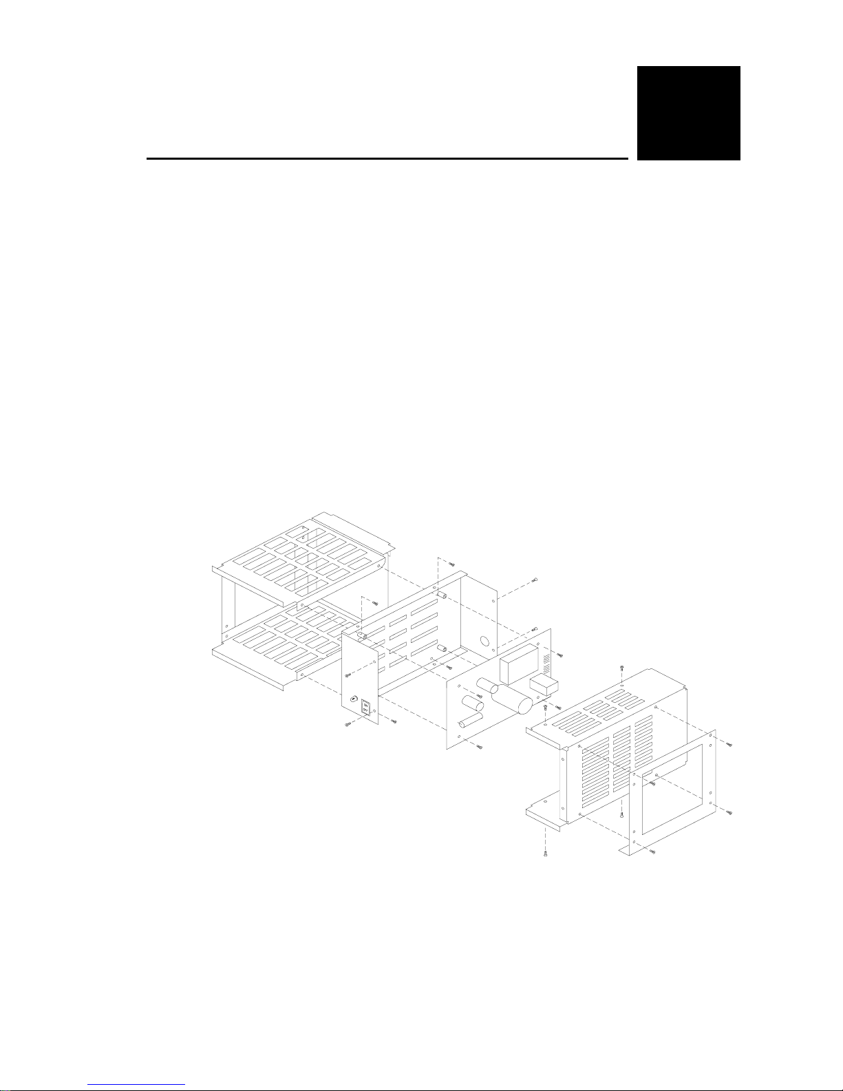
Mechanical Assembly
The power supplies are designed to mount on the right hand side of either the VX or
V32, table or rack mount, card cages.
• Remove right hand end plate.
• Remove ventilated cover on power supply.
• (VL-PS80/100 only) remove power supply circuit board for access to mounting
holes.
• Attach power supply base to card cage using four 1/4” pan head screws.
• (VL-PS80/100 only) replace power supply circuit board.
• Replace ventilated power supply cover.
• Attach right hand end plate to power supply using the four original flat head screws.
Installation
2
VL-PS Series Reference Manual Installation – 4
Figure 1. Assembly Diagram
Page 5

DC Output
DC output voltages are available on the color coded wiring harness. The front panel
indicator LED wires are also in the wiring harness and are connected to +5V and Ground
on the motherboard. Color coding is as follows:
Table 2: DC Output Connections
Color Description Quantity
Black Common ground 3
Red +5V 3
Orange +12V 1
Violet
White/Black LED Ground 1
White/Red LED +5V input 1
−12V
Installation
1
Connect only one of the black ground leads to AUX GND on the motherboard. The
other two black ground leads should be connected to GND (+5V logic ground).
AC Input
The power supplies are supplied with a standard 120 VAC USA style cord and grounded
plug. An AC input fuse is located on the power supply circuit board. The ground prong
(safety ground) is connected to the metal chassis of the power supply, but is NOT
connected to logic ground.
Front Panel
The power supplies have an AC power switch on the front panel and an LED located
next to the power switch to indicate +5V power is present on the motherboard.
VL-PS Series Reference Manual Installation – 5
Page 6
Electrical Pinouts
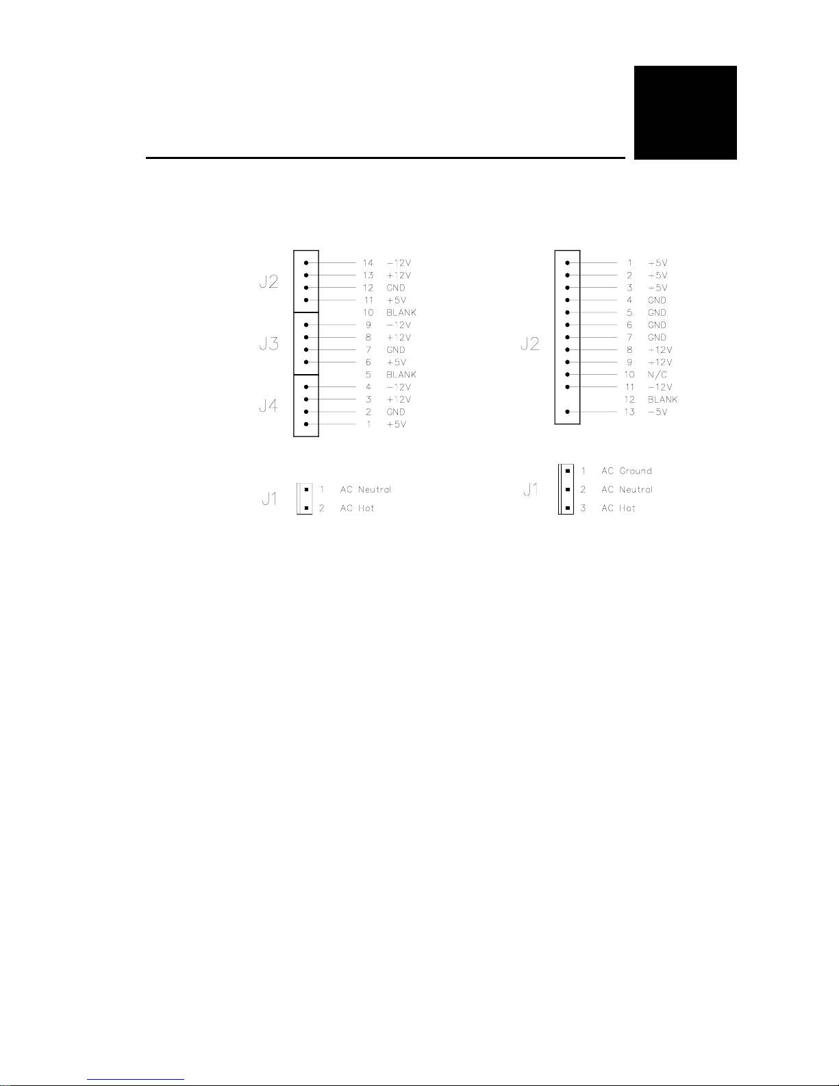
The following figures detail the AC and DC power connectors on the circuit board inside
the power supply enclosure.
3
Figure 2. VL-PS35/50 Pinout Figure 3. VL-PS80/100 Pinout
VL-PS Series Reference Manual Electrical Pinouts – 6
Page 7
Dimensions
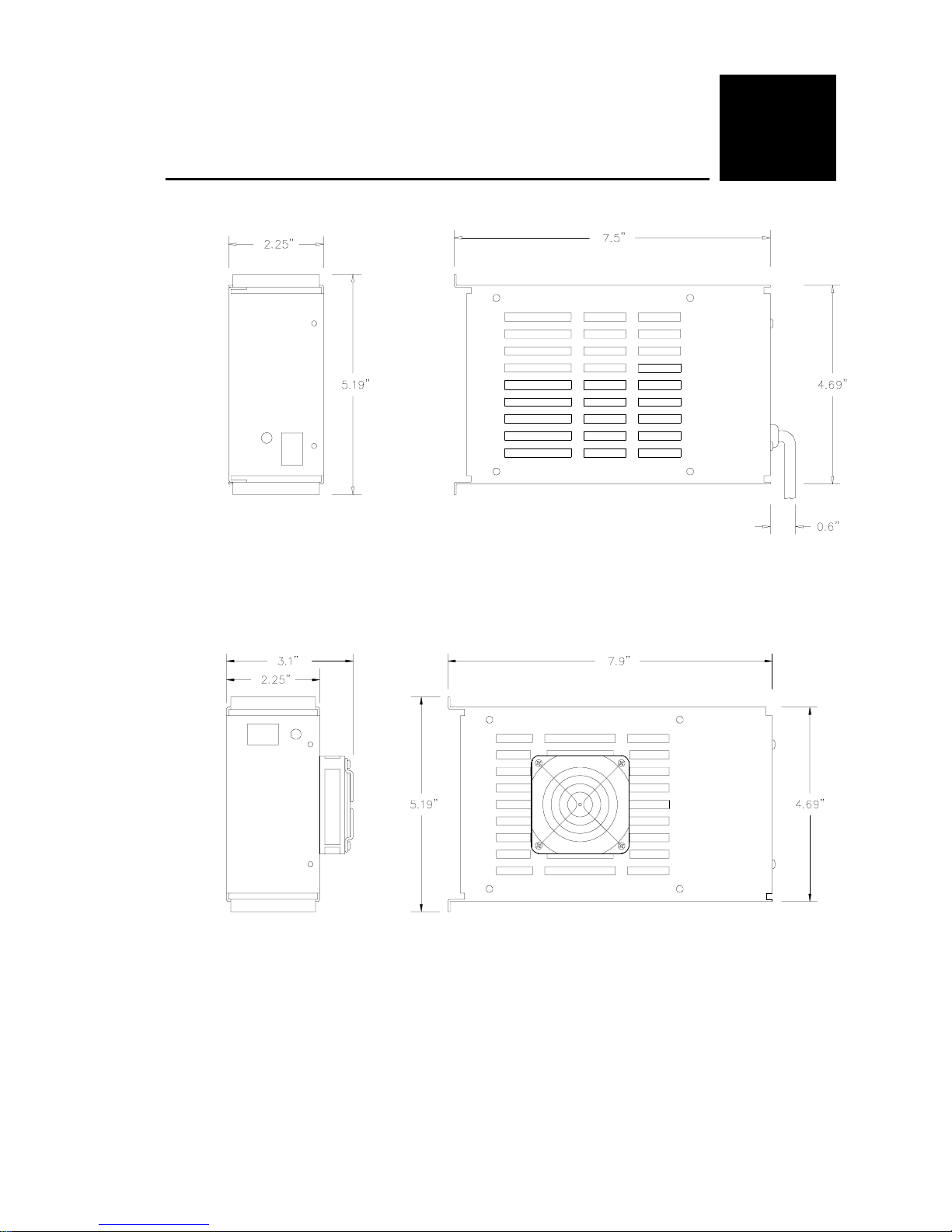
Figure 4. VL-PS35/50 Dimensions
4
VL-PS Series Reference Manual Dimensions – 7
Fan installed on VL-PS100 only.
Figure 5. VL-PS80/100 Dimensions
Page 8

Specifications
5
VL-PS35 Specifications
Input Voltage:
90 to 264 VAC
Input Frequency:
47 to 440 Hz
Conducted RFI:
Meets FCC and VDE Class B
Safety Ground Leakage:
0.5 ma Max., 132 VAC, 60 Hz
Outputs:
+5V ±2.5%, 0.5 − 3.5A
+12V ±5%, 0.2 − 2.5A, 4A peak
−12V ±5%, 0 − 0.5A
Ripple and Noise:
+5V output, ±50 mv typical
±12V outputs, ±60 mv typical
Output Voltage Adjustment:
+5V output, ±3%
Line Regulation:
0.3%, all outputs fully loaded
Turn-On Overshoot/Undershoot:
None
Transient Response:
+5V Output:
500 mv peak transient at 2.0A load change
+12V Output: 500 µs settling,
300 mv peak transient at 1.0A load change
Temperature Coefficient:
±0.03%/°C max., all outputs
Overvoltage Protection Threshold:
+5V output, 6.25V ±0.75V
Total Output Power:
0 − 35W continuous at 50°C
Hold Up Time:
12 ms with 110 VAC, 60 Hz input
Storage Temperature:
−20° to +85°C
Operating Temperature:
0° to +50°C, full power output
50° to +70°C, derate output to 25W
Relative Humidity:
5% to 95%, non-condensing
Size:
5.2" H x 2.25" W x 7.5" D
Weight:
2 lbs. 10 oz.
MTBF:
125,000 hours
500 µs settling,
VL-PS50 Specifications
Input Voltage:
90 to 264 VAC
Input Frequency:
47 to 440 Hz
Conducted RFI:
Meets FCC and VDE Class B
Safety Ground Leakage:
0.5 ma Max., 132 VAC, 60 Hz
Outputs:
+5V ±2.5%, 0.5 − 6.0A
+12V ±5%, 0.2 − 2.5A, 4A peak
−12V ±5%, 0 − 0.5A
Ripple and Noise:
+5V output, ±50 mv typical
±12V outputs, ±60 mv typical
Output Voltage Adjustment:
+5V output, ±3%
Line Regulation:
0.3%, all outputs fully loaded
Turn-On Overshoot/Undershoot:
None
Transient Response:
+5V output: 500 µs settling,
500 mv peak transient at 2.5A load change
+12V output: 500 µs settling,
300 mv peak transient at 1.0A load change
Temperature Coefficient:
±0.03%/°C max., all outputs
Overvoltage Protection Threshold:
+5V output, 6.25V ±0.75V
Total Output Power:
0 − 50W continuous at 50°C
Hold Up Time:
16 ms with 110 VAC, 60 Hz input
Storage Temperature:
−20° to +85°C
Operating Temperature:
0° to +50°C, full power output
50° to +70°C, derate output to 25W
Relative Humidity:
5% to 95%, non-condensing
Size:
5.2" H x 2.25" W x 7.5" D
Weight:
2 lbs. 10 oz.
MTBF:
125,000 hours
Specifications are subject to change without notice.
VL-PS Series Reference Manual Specifications – 8
Page 9

Specifications
VL-PS80 Specifications
Input Voltage:
85 to 264 VAC
Input Frequency:
47 to 63 Hz
Conducted RFI:
Meets FCC and VDE limit B
Safety Ground Leakage:
0.5 ma max., 132 VAC, 60 Hz
Outputs:
Convection cooled, 80W max.
+5V ±2.5%, 1.0 – 10.0A
+12V ±5%, 0 – 2.5A, 4.0A peak
–12V ±5%, 0 – 0.5A
Ripple and Noise:
+5V output, ±50 mv typical
±12V outputs, ±60 mv typical
Output Voltage Adjustment:
+5V output, ±3%
Line Regulation:
0.3%, all outputs fully loaded
Turn-On Overshoot/Undershoot:
< 3%
Transient Response:
+5V output, 500µs settling,
200 mv peak transient at 2.5A load change
+12V output, 500 µs settling,
100 mv peak transient at 1A load change
Temperature Coefficient:
±0.03%/°C max., all outputs
Overvoltage Protection Threshold:
+5V output, 6.25V ±0.75V
Total Output Power:
5 – 80W continuous at 50°C
Hold Up Time:
20 ms with 110 VAC, 60 Hz input
Storage Temperature:
–20° to +85°C
Operating Temperature:
0° to +50°C, full power output
+50° to +70°C, derate output to 50%
Relative Humidity:
5% to 95%, non-condensing
Size:
5.2"H x 2.25"W x 7.9"D
Weight:
3 lbs. 2 oz.
MTBF:
125,000 hours
VL-PS100 Specifications
Input Voltage:
85 to 264 VAC
Input Frequency:
47 to 63 Hz
Conducted RFI:
Meets FCC and VDE limit B
Safety Ground Leakage:
0.5 ma max., 132 VAC, 60 Hz
Outputs:
Forced air cooled @ 20 CFM, 100W max.
+5V ±2.5%, 1.0 – 12.0A
+12V ±5%, 0 – 3.0A, 4.0A peak
–12V ±5%, 0 – 1.0A
Ripple and Noise:
+5V output, ±50 mv typical
±12V outputs, ±60 mv typical
Output Voltage Adjustment:
+5V output, ±3%
Line Regulation:
0.3%, all outputs fully loaded
Turn-On Overshoot/Undershoot:
< 3%
Transient Response:
+5V output, 500 µs settling,
200 mv peak transient at 2.5A load change
+12V output, 500 µs settling,
100 mv peak transient at 1A load change
Temperature Coefficient:
±0.03%/°C max., all outputs
Overvoltage Protection Threshold:
+5V output, 6.25V ±0.75V
Total Output Power:
5 – 100W continuous at 50°C and 20 CFM
Hold Up Time:
20 ms with 110 VAC, 60 Hz input
Storage Temperature:
–20° to +85°C
Operating Temperature:
0° to +50°C, full power output
+50° to +70°C, derate output to 50%
Relative Humidity:
5% to 95%, non-condensing
Size:
5.2"H x 3.1"W x 7.9"D
Weight:
3 lbs. 5 oz.
MTBF:
125,000 hours
Specifications are subject to change without notice.
VL-PS Series Reference Manual Specifications – 9
 Loading...