

VersaLogic VL-EPMs-U1, VL-EPMs-U1A, VL-EPMs-U1B, VL-EPMs-U1C, VL-EPMs-U1D Reference Manual
...
Reference
Manual
DOC. REV. 4/9/2013
VL-EPMs-U1
SUMIT-ISM™ Serial
Communications + GPS Module
WWW.VERSALOGIC.COM
12100 SW Tualatin Road
Tualatin, OR 97062-7341
(503) 747-2261
Fax (971) 224-4708
Copyright © 2013 VersaLogic Corp. All rights reserved.
Notice:
Although every effort has been made to ensure this document is error-free, VersaLogic makes no
representations or warranties with respect to this product and specifically disclaims any implied warranties
of merchantability or fitness for any particular purpose.
VersaLogic reserves the right to revise this product and associated documentation at any time without
obligation to notify anyone of such changes.
PC/104 and the PC/104 logo are trademarks of the PC/104 Consortium. SUMIT, ISM, SUMIT-ISM, and the
SUMIT logo are trademarks of the Small Form Factor Special Interest Group (SFF-SIG). All other product
names and trademarks, registered trademarks, or service marks are property of their respective owners.
VL-EPMs-U1 Reference Manual ii
Product Release Notes
VersaTech KnowledgeBase
Rev 1.00 – Commercial Release.
Support Page
The VL-EPMs-U1 support page, at http://www.versalogic.com/private/epmsu1support.asp, contains
additional information and resources for this product including:
Reference Manual (PDF format)
Device drivers
Datasheets and manufacturers’ links for chips used in this product
Photograph of the circuit board
BIOS information and upgrades
Utility routines and benchmark software
This is a private page for VL-EPMs-U1 users that can be accessed only by entering this URL address
directly. It cannot be reached from the VersaLogic public website.
The VersaTech KnowledgeBase is an invaluable resource for resolving technical issues with your
VersaLogic product.
VL-EPMs-U1 Reference Manual iii

Contents
Introduction ................................................................................................................... 1
Features ............................................................................................................................... 1
Technical Specifications ..................................................................................................... 2
Block Diagram .................................................................................................................... 3
RoHS-Compliance .............................................................................................................. 4
About RoHS ........................................................................................................... 4
Warnings ............................................................................................................................. 4
Electrostatic Discharge .......................................................................................... 4
Technical Support ............................................................................................................... 5
Repair Service ........................................................................................................ 5
Physical Description ..................................................................................................... 6
Dimensions and Mounting .................................................................................................. 6
Hardware Assembly ............................................................................................... 8
Stacking Restrictions ............................................................................................. 9
External Connectors ......................................................................................................... 10
VL-EPMs-U1 Connectors.................................................................................... 10
VL-EPMs-U1 Connector Functions and Interface Cables .................................. 11
Jumper Blocks .................................................................................................................. 12
Jumpers As-shipped Configuration ..................................................................... 12
Jumper Summary ................................................................................................. 13
Operation ..................................................................................................................... 14
Serial Ports ........................................................................................................................ 14
Serial Port Connectors ......................................................................................... 15
GPS and Antenna .............................................................................................................. 18
Antenna Connector (J5) ....................................................................................... 18
Battery Back-up ................................................................................................... 18
Coordinate Systems ............................................................................................. 20
Performance Characteristics ................................................................................ 21
Start-up ................................................................................................................ 22
SUMIT-A Top Connector (J6) ......................................................................................... 23
SUMIT-B Top Connector (J7) .......................................................................................... 24
PC/104 (ISA) Connector (J10) ......................................................................................... 25
SUMIT-B Bottom Connector (J11) .................................................................................. 25
SUMIT-A Bottom Connector (J12) .................................................................................. 26
Appendix A – References............................................................................................ 27
VL-EPMs-U1 Reference Manual iv

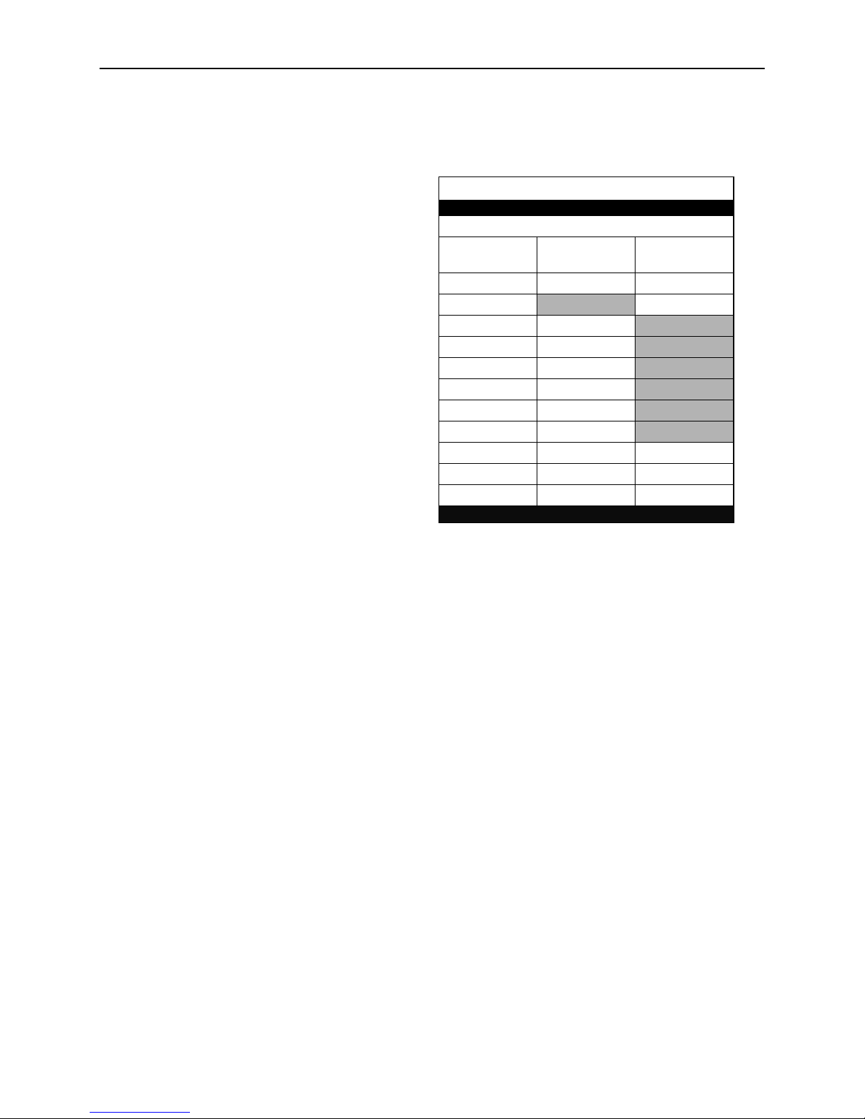
Model
Availability
Serial
Channels
GPS
Connectors
VL-EPMs-U1A
Standard
4
No
SUMIT-A
VL-EPMs-U1B
Standard
6
No
SUMIT-A
VL-EPMs-U1C
Standard
4
No
SUMIT-AB + ISA
VL-EPMs-U1D
Special Order
6
No
SUMIT-AB + ISA
VL-EPMs-U1E
Standard
2*
Yes
SUMIT-A
VL-EPMs-U1F
Special Order
4*
Yes
SUMIT-A
VL-EPMs-U1G
Special Order
2*
Yes
SUMIT-AB + ISA
VL-EPMs-U1H
Special Order
4*
Yes
SUMIT-AB + ISA
Transient Voltage Suppression
(TVS) devices on I/O interfaces
for protection against power
spikes and surges
Designed to provide -40° to
+85°C operation for reliable use
in harsh environments
Full compliance with EU Directive
2002/95/EC (RoHS) for devices used in
Europe
SUMIT-ISM (Legacy Type 1) form factor
1
Features
The VL-EPMs-U1 is an embedded serial communications module with global positioning system
(GPS) capability. Based on the SUMIT-ISM form factor, the VL-EPMs-U1 supports SUMIT and
PC/104 stackable expansion buses on a 95 mm x 96 mm (3.76” x 3.78”) footprint.
Configurations and feature sets include:
Introduction
* Indicates the number of serial channels available for user I/O. The two serial channels
(COM3-4) dedicated to the GPS interface are not included in this number.
All boards include the following features:
The VL-EPMs-U1 features high-reliability design and construction. All VL-EPMs-U1 boards are
subjected to functional testing and are backed by a limited two-year warranty. Careful parts
sourcing and US-based technical support ensure the highest possible quality, reliability, service,
and product longevity for this exceptional board.
VL-EPMs-U1 Reference Manual 1
Technical Specifications
Board Size:
ISM™/PC/104™ standard:
90 mm x 96 mm (3.55” x 3.78”)
Power Requirements:
+5V @ 140 mA (700 mW)
Stackable Bus:
SUMIT: SUMIT-A, SUMIT-B*
PC/104*: ISA (pass-through only)
Operating Temperature:
-40° to +85°C
Storage Temperature:
-40° to +85°C
Airflow Requirements:
Free air from -40° to +85°C
COM1/COM2:
RS-232, 16C550A compatible, 115 Kbps, full
handshaking to support DB-9 connector
(TVS protected)
COM3/COM4:
RS-232/422/485, 16C550A compatible, 460
Kbps. 4-line RS-232: Tx/Rx Data and
CTS/RTS. TVS protected. Consumed by
GPS module in GPS versions.
COM5/COM6:
RS-232/422/485, 16C550A compatible, 460
Kbps. 4-line RS-232: Tx/Rx Data and
CTS/RTS. TVS protected.
GPS*:
Trimble® Lassen® iQ GPS module
- 12-channel GPS functionality
- Supports NMEA 0183, TSIP, TAIP, and
DGPS protocols
- Consumes COM3 and COM4
- Battery-backed almanac (estimated
power-off battery life 10 yrs)
Weight:
VL-EPMs-U1A – 0.041 kg (0.088 lb)
VL-EPMs-U1B – 0.043 kg (0.096 lb)
VL-EPMs-U1C – 0.066 kg (0.146 lb)
VL-EPMs-U1E – 0.054 kg (0.120 lb)
SUMIT Resources
Form Factor: SUMIT-ISM (Legacy Type 1)
SUMIT
A
SUMIT
B*
PCIe x1
–
–
PCIe x4
–
USB
–
ExpressCard
–
LPC
1
SPI / µWire
–
SMBus / I2C
–
+12V
–
+5V
+5Vsb
–
–
+3.3V
–
–
Introduction
* Optional
Data represents standard operation at +25°C with +5V supply unless otherwise noted.
Specifications are subject to change without notification.
VL-EPMs-U1 Reference Manual 2
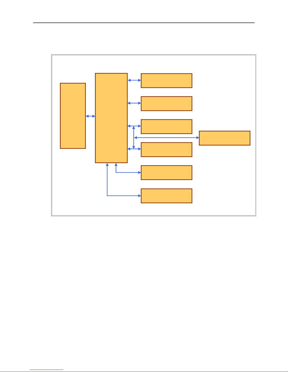
Block Diagram
SUMIT
Connectors
SCH3114
or
SCH3116
Super I/O
COM1
RS-232
COM2
RS-232
COM3
RS-232/422/485
COM6
RS-232/422/485
COM4
RS-232/422/485
COM5
RS-232/422/485
GPS Module Header
Introduction
Figure 1. VL-EPMs-U1 Block Diagram
VL-EPMs-U1 Reference Manual 3

RoHS-Compliance
The VL-EPMs-U1 is RoHS-compliant.
ABOUT ROHS
In 2003, the European Union issued Directive 2002/95/EC regarding the Restriction of the use of
certain Hazardous Substances (RoHS) in electrical and electronic equipment.
The RoHS directive requires producers of electrical and electronic equipment to reduce to
acceptable levels the presence of six environmentally sensitive substances: lead, mercury,
cadmium, hexavalent chromium, and the presence of polybrominated biphenyls (PBB) and
polybrominated diphenyl ethers (PBDE) flame retardants, in certain electrical and electronic
products sold in the European Union (EU) beginning July 1, 2006.
VersaLogic Corp. is committed to supporting customers with high-quality products and services
meeting the European Union’s RoHS directive.
Warnings
Introduction
ELECTROSTATIC DISCHARGE
Electrostatic discharge (ESD) can damage boards, disk drives, and other components. The circuit
board must only be handled at an ESD protective workstation. If an approved station is not
available, some measure of protection can be provided by wearing a grounded antistatic wrist
strap. Keep all plastic away from the board. Do not slide the board over any surface.
After removing the board from its protective wrapper, place the board on a grounded, static-free
surface, component side up. Use an antistatic foam pad if available.
The board should always be protected inside a closed metallic antistatic envelope during
shipment or storage.
VL-EPMs-U1 Reference Manual 4
Technical Support
VL-EPMs-U1 Support Page
http://www.versalogic.com/private/epmsu1support.asp
VersaTech KnowledgeBase
If you are unable to solve a problem after reading this manual, please visit the VL-EPMs-U1
product support web page (see below). The support page provides links to component datasheets
and device drivers.
The VersaTech KnowledgeBase contains a wealth of technical information about VersaLogic
products, along with product advisories. Click the link below to see all KnowledgeBase articles
related to the VL-EPMs-U1.
Introduction
If you have further questions, contact VersaLogic Technical Support at (503) 747-2261.
VersaLogic support engineers are also available via e-mail at Support@VersaLogic.com.
REPAIR SERVICE
If your product requires service, you must obtain a Returned Material Authorization (RMA)
number by calling (503) 747-2261.
Please provide the following information:
Your name, the name of your company, your phone number, and your e-mail address
The name of a technical contact if any questions arise
Quantity of items being returned
The model and serial number (barcode) of each item
A detailed description of the problem
Steps you have taken to resolve or recreate the problem
The return shipping address
Warranty Repair All parts and labor charges are covered, including return shipping
charges for UPS Ground delivery to United States addresses.
Non-warranty Repair All non-warranty repairs are subject to diagnosis and labor charges,
parts charges, and return shipping fees. Please specify the shipping
method you prefer and provide a purchase order number for invoicing
the repair.
Note Please mark the RMA number clearly on the outside of the box before
VL-EPMs-U1 Reference Manual 5
returning. Failure to do so can delay the processing of your return.

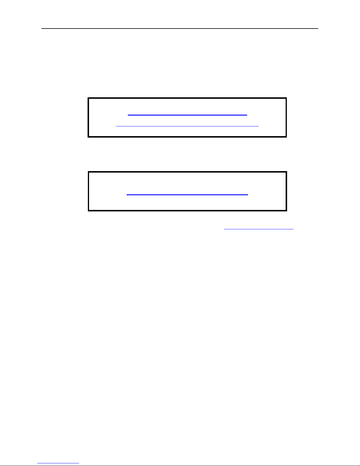
2
–0.200
0.000
3.150
3.350
0.150
0.000
-0.200
3.575
3.375
3.050
0.125 DIA x4
Use 3mm or #4
standoffs
+ + +
+
Dimensions and Mounting
The VL-EPMs-U1 complies with SUMIT-ISM (Legacy Type 1) form factor, which provides for
specific mounting hole and stackable bus locations as shown in the diagram below.
Physical Description
Caution The board must be supported at all four mounting points to prevent excessive
flexing when expansion modules are mated and detached. Flex damage caused by
excessive force on an improperly mounted circuit board is not covered under the
product warranty.
VL-EPMs-U1 Reference Manual 6
Figure 2. VL-EPMs-U1 Dimensions and Mounting Holes
(Not to scale. All dimensions in inches.)
 Loading...