

VersaLogic VL-EPMs-U1, VL-EPMs-U1A, VL-EPMs-U1B, VL-EPMs-U1C, VL-EPMs-U1D Reference Manual
...Page 1

Reference
Manual
DOC. REV. 4/9/2013
VL-EPMs-U1
SUMIT-ISM™ Serial
Communications + GPS Module
Page 2

WWW.VERSALOGIC.COM
12100 SW Tualatin Road
Tualatin, OR 97062-7341
(503) 747-2261
Fax (971) 224-4708
Copyright © 2013 VersaLogic Corp. All rights reserved.
Notice:
Although every effort has been made to ensure this document is error-free, VersaLogic makes no
representations or warranties with respect to this product and specifically disclaims any implied warranties
of merchantability or fitness for any particular purpose.
VersaLogic reserves the right to revise this product and associated documentation at any time without
obligation to notify anyone of such changes.
PC/104 and the PC/104 logo are trademarks of the PC/104 Consortium. SUMIT, ISM, SUMIT-ISM, and the
SUMIT logo are trademarks of the Small Form Factor Special Interest Group (SFF-SIG). All other product
names and trademarks, registered trademarks, or service marks are property of their respective owners.
VL-EPMs-U1 Reference Manual ii
Page 3

Product Release Notes
VersaTech KnowledgeBase
Rev 1.00 – Commercial Release.
Support Page
The VL-EPMs-U1 support page, at http://www.versalogic.com/private/epmsu1support.asp, contains
additional information and resources for this product including:
Reference Manual (PDF format)
Device drivers
Datasheets and manufacturers’ links for chips used in this product
Photograph of the circuit board
BIOS information and upgrades
Utility routines and benchmark software
This is a private page for VL-EPMs-U1 users that can be accessed only by entering this URL address
directly. It cannot be reached from the VersaLogic public website.
The VersaTech KnowledgeBase is an invaluable resource for resolving technical issues with your
VersaLogic product.
VL-EPMs-U1 Reference Manual iii
Page 4

Contents
Introduction ................................................................................................................... 1
Features ............................................................................................................................... 1
Technical Specifications ..................................................................................................... 2
Block Diagram .................................................................................................................... 3
RoHS-Compliance .............................................................................................................. 4
About RoHS ........................................................................................................... 4
Warnings ............................................................................................................................. 4
Electrostatic Discharge .......................................................................................... 4
Technical Support ............................................................................................................... 5
Repair Service ........................................................................................................ 5
Physical Description ..................................................................................................... 6
Dimensions and Mounting .................................................................................................. 6
Hardware Assembly ............................................................................................... 8
Stacking Restrictions ............................................................................................. 9
External Connectors ......................................................................................................... 10
VL-EPMs-U1 Connectors.................................................................................... 10
VL-EPMs-U1 Connector Functions and Interface Cables .................................. 11
Jumper Blocks .................................................................................................................. 12
Jumpers As-shipped Configuration ..................................................................... 12
Jumper Summary ................................................................................................. 13
Operation ..................................................................................................................... 14
Serial Ports ........................................................................................................................ 14
Serial Port Connectors ......................................................................................... 15
GPS and Antenna .............................................................................................................. 18
Antenna Connector (J5) ....................................................................................... 18
Battery Back-up ................................................................................................... 18
Coordinate Systems ............................................................................................. 20
Performance Characteristics ................................................................................ 21
Start-up ................................................................................................................ 22
SUMIT-A Top Connector (J6) ......................................................................................... 23
SUMIT-B Top Connector (J7) .......................................................................................... 24
PC/104 (ISA) Connector (J10) ......................................................................................... 25
SUMIT-B Bottom Connector (J11) .................................................................................. 25
SUMIT-A Bottom Connector (J12) .................................................................................. 26
Appendix A – References............................................................................................ 27
VL-EPMs-U1 Reference Manual iv
Page 5

Model
Availability
Serial
Channels
GPS
Connectors
VL-EPMs-U1A
Standard
4
No
SUMIT-A
VL-EPMs-U1B
Standard
6
No
SUMIT-A
VL-EPMs-U1C
Standard
4
No
SUMIT-AB + ISA
VL-EPMs-U1D
Special Order
6
No
SUMIT-AB + ISA
VL-EPMs-U1E
Standard
2*
Yes
SUMIT-A
VL-EPMs-U1F
Special Order
4*
Yes
SUMIT-A
VL-EPMs-U1G
Special Order
2*
Yes
SUMIT-AB + ISA
VL-EPMs-U1H
Special Order
4*
Yes
SUMIT-AB + ISA
Transient Voltage Suppression
(TVS) devices on I/O interfaces
for protection against power
spikes and surges
Designed to provide -40° to
+85°C operation for reliable use
in harsh environments
Full compliance with EU Directive
2002/95/EC (RoHS) for devices used in
Europe
SUMIT-ISM (Legacy Type 1) form factor
1
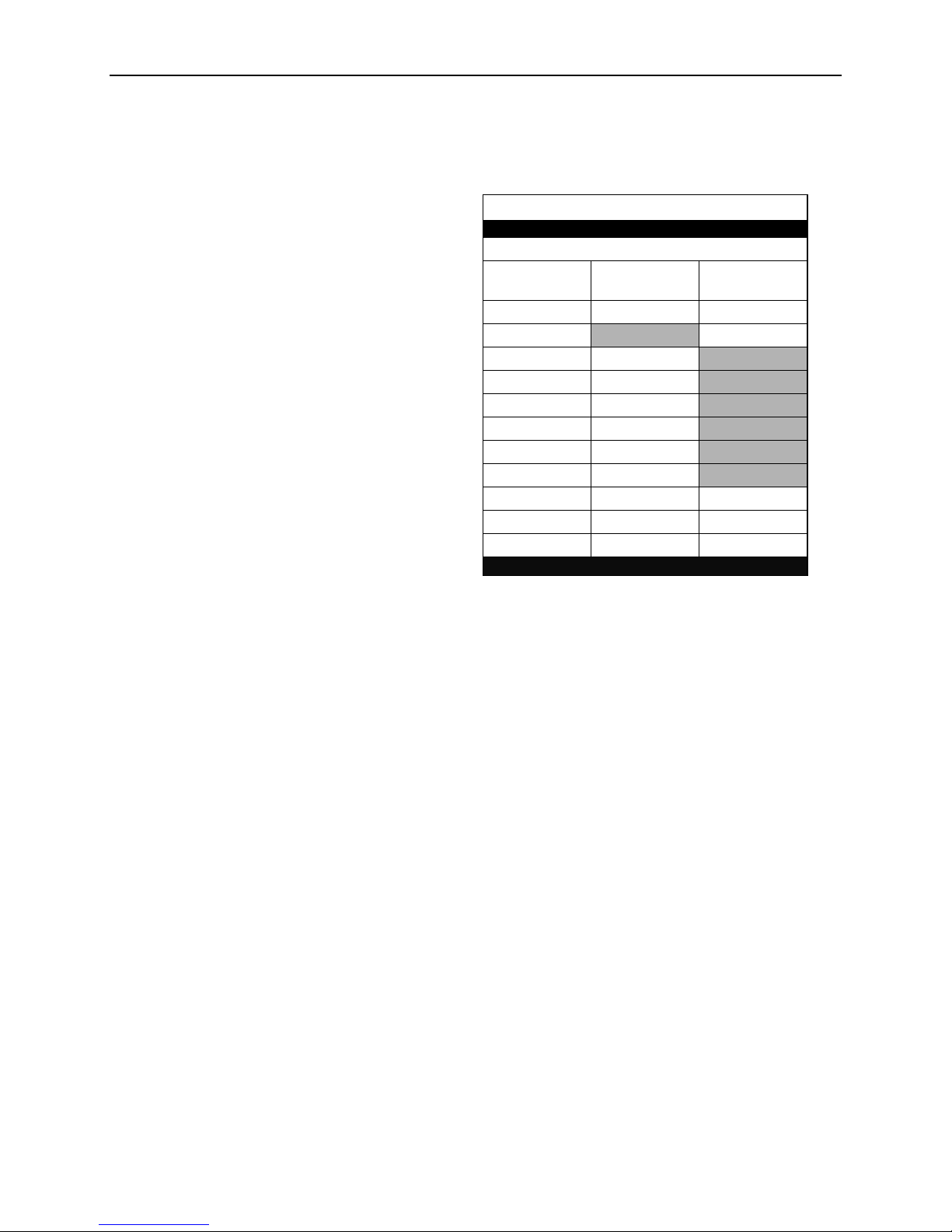
Features
The VL-EPMs-U1 is an embedded serial communications module with global positioning system
(GPS) capability. Based on the SUMIT-ISM form factor, the VL-EPMs-U1 supports SUMIT and
PC/104 stackable expansion buses on a 95 mm x 96 mm (3.76” x 3.78”) footprint.
Configurations and feature sets include:
Introduction
* Indicates the number of serial channels available for user I/O. The two serial channels
(COM3-4) dedicated to the GPS interface are not included in this number.
All boards include the following features:
The VL-EPMs-U1 features high-reliability design and construction. All VL-EPMs-U1 boards are
subjected to functional testing and are backed by a limited two-year warranty. Careful parts
sourcing and US-based technical support ensure the highest possible quality, reliability, service,
and product longevity for this exceptional board.
VL-EPMs-U1 Reference Manual 1
Page 6
Technical Specifications
Board Size:
ISM™/PC/104™ standard:
90 mm x 96 mm (3.55” x 3.78”)
Power Requirements:
+5V @ 140 mA (700 mW)
Stackable Bus:
SUMIT: SUMIT-A, SUMIT-B*
PC/104*: ISA (pass-through only)
Operating Temperature:
-40° to +85°C
Storage Temperature:
-40° to +85°C
Airflow Requirements:
Free air from -40° to +85°C
COM1/COM2:
RS-232, 16C550A compatible, 115 Kbps, full
handshaking to support DB-9 connector
(TVS protected)
COM3/COM4:
RS-232/422/485, 16C550A compatible, 460
Kbps. 4-line RS-232: Tx/Rx Data and
CTS/RTS. TVS protected. Consumed by
GPS module in GPS versions.
COM5/COM6:
RS-232/422/485, 16C550A compatible, 460
Kbps. 4-line RS-232: Tx/Rx Data and
CTS/RTS. TVS protected.
GPS*:
Trimble® Lassen® iQ GPS module
- 12-channel GPS functionality
- Supports NMEA 0183, TSIP, TAIP, and
DGPS protocols
- Consumes COM3 and COM4
- Battery-backed almanac (estimated
power-off battery life 10 yrs)
Weight:
VL-EPMs-U1A – 0.041 kg (0.088 lb)
VL-EPMs-U1B – 0.043 kg (0.096 lb)
VL-EPMs-U1C – 0.066 kg (0.146 lb)
VL-EPMs-U1E – 0.054 kg (0.120 lb)
SUMIT Resources
Form Factor: SUMIT-ISM (Legacy Type 1)
SUMIT
A
SUMIT
B*
PCIe x1
–
–
PCIe x4
–
USB
–
ExpressCard
–
LPC
1
SPI / µWire
–
SMBus / I2C
–
+12V
–
+5V
+5Vsb
–
–
+3.3V
–
–
Introduction
* Optional
Data represents standard operation at +25°C with +5V supply unless otherwise noted.
Specifications are subject to change without notification.
VL-EPMs-U1 Reference Manual 2
Page 7
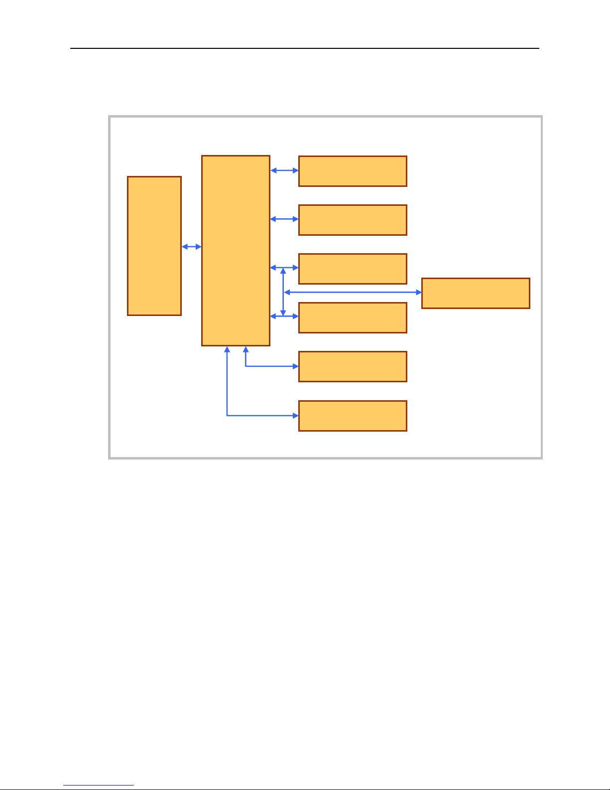
Block Diagram
SUMIT
Connectors
SCH3114
or
SCH3116
Super I/O
COM1
RS-232
COM2
RS-232
COM3
RS-232/422/485
COM6
RS-232/422/485
COM4
RS-232/422/485
COM5
RS-232/422/485
GPS Module Header
Introduction
Figure 1. VL-EPMs-U1 Block Diagram
VL-EPMs-U1 Reference Manual 3
Page 8

RoHS-Compliance
The VL-EPMs-U1 is RoHS-compliant.
ABOUT ROHS
In 2003, the European Union issued Directive 2002/95/EC regarding the Restriction of the use of
certain Hazardous Substances (RoHS) in electrical and electronic equipment.
The RoHS directive requires producers of electrical and electronic equipment to reduce to
acceptable levels the presence of six environmentally sensitive substances: lead, mercury,
cadmium, hexavalent chromium, and the presence of polybrominated biphenyls (PBB) and
polybrominated diphenyl ethers (PBDE) flame retardants, in certain electrical and electronic
products sold in the European Union (EU) beginning July 1, 2006.
VersaLogic Corp. is committed to supporting customers with high-quality products and services
meeting the European Union’s RoHS directive.
Warnings
Introduction
ELECTROSTATIC DISCHARGE
Electrostatic discharge (ESD) can damage boards, disk drives, and other components. The circuit
board must only be handled at an ESD protective workstation. If an approved station is not
available, some measure of protection can be provided by wearing a grounded antistatic wrist
strap. Keep all plastic away from the board. Do not slide the board over any surface.
After removing the board from its protective wrapper, place the board on a grounded, static-free
surface, component side up. Use an antistatic foam pad if available.
The board should always be protected inside a closed metallic antistatic envelope during
shipment or storage.
VL-EPMs-U1 Reference Manual 4
Page 9
Technical Support
VL-EPMs-U1 Support Page
http://www.versalogic.com/private/epmsu1support.asp
VersaTech KnowledgeBase
If you are unable to solve a problem after reading this manual, please visit the VL-EPMs-U1
product support web page (see below). The support page provides links to component datasheets
and device drivers.
The VersaTech KnowledgeBase contains a wealth of technical information about VersaLogic
products, along with product advisories. Click the link below to see all KnowledgeBase articles
related to the VL-EPMs-U1.
Introduction
If you have further questions, contact VersaLogic Technical Support at (503) 747-2261.
VersaLogic support engineers are also available via e-mail at Support@VersaLogic.com.
REPAIR SERVICE
If your product requires service, you must obtain a Returned Material Authorization (RMA)
number by calling (503) 747-2261.
Please provide the following information:
Your name, the name of your company, your phone number, and your e-mail address
The name of a technical contact if any questions arise
Quantity of items being returned
The model and serial number (barcode) of each item
A detailed description of the problem
Steps you have taken to resolve or recreate the problem
The return shipping address
Warranty Repair All parts and labor charges are covered, including return shipping
charges for UPS Ground delivery to United States addresses.
Non-warranty Repair All non-warranty repairs are subject to diagnosis and labor charges,
parts charges, and return shipping fees. Please specify the shipping
method you prefer and provide a purchase order number for invoicing
the repair.
Note Please mark the RMA number clearly on the outside of the box before
VL-EPMs-U1 Reference Manual 5
returning. Failure to do so can delay the processing of your return.
Page 10

2
–0.200
0.000
3.150
3.350
0.150
0.000
-0.200
3.575
3.375
3.050
0.125 DIA x4
Use 3mm or #4
standoffs
+ + +
+
Dimensions and Mounting
The VL-EPMs-U1 complies with SUMIT-ISM (Legacy Type 1) form factor, which provides for
specific mounting hole and stackable bus locations as shown in the diagram below.
Physical Description
Caution The board must be supported at all four mounting points to prevent excessive
flexing when expansion modules are mated and detached. Flex damage caused by
excessive force on an improperly mounted circuit board is not covered under the
product warranty.
VL-EPMs-U1 Reference Manual 6
Figure 2. VL-EPMs-U1 Dimensions and Mounting Holes
(Not to scale. All dimensions in inches.)
Page 11

Physical Description
0.44
0.43
0.06
0.38
0.36
PC/104 (ISA)
Connector
SUMIT
Connectors
Serial Port
Connectors
GPS Antenna
Connector
0.39
Figure 3. VL-EPMs-U1x Height Dimensions
(Not to scale. All dimensions in inches.)
Note Not all connectors are present on all models.
VL-EPMs-U1 Reference Manual 7
Page 12

Physical Description
HARDWARE ASSEMBLY
The VL-EPMs-U1 comes in a variety of configurations that use SUMIT-A only, SUMIT-A and
SUMIT-B, and PC/104 (ISA) connectors. The module can be added to the middle or top of the
stack, above any SUMIT boards and below any PC/104 boards.
The entire assembly can sit on a table top or be secured to a base plate. When bolting the unit
down, make sure to secure all four standoffs to the mounting surface to prevent circuit board
flexing. Standoffs are secured to the top circuit board using four pan head screws. Standoffs and
screws are available (VL-HDW-105/VL-HDW-106). Note that the standoffs in this kit are 15.24
mm (0.6") and must not be mixed with 15 mm (0.59") standoffs (VL-HDW-100/VL-HDW-101).
An extractor tool is available (part number VL-HDW-201) to separate modules from the stack.
Use caution when using the extractor tool so as not to damage any board components.
VL-EPMs-U1 Reference Manual 8
Figure 4. Stacking Example
Page 13

Physical Description
STACKING RESTRICTIONS
The VL-EPMs-U1 can be used with any SUMIT-enabled VersaLogic CPU board, though some
restrictions apply, as described below.
VL-EPMs-21 and VL-EPICs-36 Restrictions
The following restrictions apply when using the VL-EPMs-21 or VL-EPICs-36:
A maximum of two VL-EPMs-U1 boards are supported in the stack.
When two VL-EPMs-U1 boards are in the stack, one must be configured with a base
address of 0x4E. The other board must be configured to 0x162E or 0x164E. Address
0x2E is reserved for the CPU board's Super I/O.
I/O base address availability is limited. Generally, each base address option is port
specific. Eighteen I/O base addresses are available to all ports, but address options for a
particular port are limited to three.
Interrupts can be shared among serial ports on the same VL-EPMs-U1 board, but not
shared among serial ports on different boards (that is, serial ports originating from
different super I/O chips).
The serial ports on the VL-EPMs-U1 must be added manually in Windows using the Add
Hardware Wizard and the Device Manager. The module is not plug-and-play.
BIOS console redirection to VL-EPMs-U1 serial ports cannot be activated using the
Ctrl-C keyboard combination. However, the OS can redirect the console to VL-EPMsU1 ports.
Additional VL-EPICs-36 Restrictions
The following restrictions pertain to the VL-EPICs-36 only:
A maximum of three I/O ranges can be allocated to VL-EPMs-U1 serial ports. You
should configure the ports to use contiguous I/O space to best utilize these decode
ranges. The following base addresses are exempt from this restriction: 3F8, 2F8, 208,
and 200.
Including on-board serial ports, a maximum of 16 ports can be configured. The system
will display a warning if the BIOS cannot allocate enough I/O space.
VL-EPMs-U1 Reference Manual 9
Page 14

External Connectors
J6 – SUMIT-A
All models
J7 – SUMIT-B
Models C, D, G, H
J10 – PC/104 (ISA)
Models C, D, G, H
J8 – GPS
GPS Models
J5 – Antenna
GPS Models
J3 – COM5-6
Models
B, D, F, H
J2 – COM3-4
Models A, B, C, D
J4 – COM1-2
All Models
J9 – GPS to
Antenna
GPS Models
Battery
VL-EPMS-U1 CONNECTORS
Physical Description
VL-EPMs-U1 Reference Manual 10
Figure 5. VL-EPMs-U1 Connectors – Top Side
Page 15

Physical Description
Connector
Function
Mating Connector
Transition
Cable
Cable Description
Pin 1 Location1
x coord. y coord.
Page
J1
Not installed
— — —
0.614
3.401
—
J2
COM3/4
3M 89120-0101
VL-CBR-2001
12" 20-pin socket to
two DB-9
3.099
2.969
16
J3
COM5/6
3M 89120-0101
VL-CBR-2001
12" 20-pin socket to
two DB-9M
0.047
1.723
17
J4
COM1/2
3M 89120-0101
VL-CBR-2001
12"' 20-pin socket to
two DB-9M
3.099
1.513
15
J5
GPS Antenna
SubMiniature A (SMA)
male
VL-CBR-ANT02
5m Trimble antenna
—
—
18
J6
SUMIT-A (Top)
Samtec ASP-129646-01
— — 2.712
3.322
23
J7
SUMIT-B (Top)
Samtec ASP-129646-01
— — 1.669
3.322
24
J8
GPS header
— — (GPS) — —
18
J9
GPS to Antenna
— — (Supplied with GPS)
—
—
18
J10
PC/104 ISA
AMP 1375795-2
— — 0.050
0.200
25
J11
SUMIT-B (Bottom)
Samtec ASP-129637-01
— — 1.669
3.317
25
J12
SUMIT-A (Bottom)
Samtec ASP-129637-01
— — 2.712
3.317
26
VL-EPMS-U1 CONNECTOR FUNCTIONS AND INTERFACE CABLES
The following table notes the function of each connector, as well as mating connectors and
cables, and the page where a detailed pinout or further information is available.
Table 1: Connector Functions and Interface Cables
1. The PCB origin is the center of the mounting hole located in the lower left, as oriented in Figure 5.
VL-EPMs-U1 Reference Manual 11
Page 16

Jumper Blocks
1 2
V4
V5
V3
1
2
1 2 3
2 1
1 2 3
V2
V1
3 4
4 3
(Model E)
(Model B)
(Models A, B, C)
(All models)
(All models)
Jumper headers are
present only on the
standard VL-EPMs-U1
models indicated here.
JUMPERS AS-SHIPPED CONFIGURATION
Physical Description
VL-EPMs-U1 Reference Manual 12
Figure 6. As-shipped Jumper Configuration
Page 17

Physical Description
Jumper
Block
Description
As
Shipped
Page
V1[1-2]
GPS Backup power. This jumper header is installed on the VLEPMs-U1B and E only.
In – GPS almanac backup power is connected
Out – GPS almanac backup power is not connected
Either through an installed lithium battery or external power source
via J1, backup power can optionally be supplied to the GPS unit to
maintain its almanac, ephemeris, and last position for faster initial
position fixes upon system power up (10 seconds typical).
In
(Model E
only)
—
V2[1-2]
COM5 RS-422/485 Termination Resistor. This jumper header is
installed on the VL-EPMs-U1B only.
In – COM5 terminated
Out – No termination
Installing a jumper places a 120 ohm terminating resistor across the
COM5 RxD+/RxD- differential pair.
In
(Model B
only)
17
V2[3-4]
COM6 RS-422/485 Termination Resistor. This jumper header is
installed on the VL-EPMs-U1B only.
In – COM6 terminated
Out – No termination
Installing a jumper places a 120 ohm terminating resistor across the
COM6 RxD+/RxD- differential pair.
In
(Model B
only)
17
V3[1-2]
COM3 RS-422/485 Termination Resistor. This jumper header is
installed on the VL-EPMs-U1A, B, and C only.
In – COM3 terminated
Out – No termination
Installing a jumper places a 120 ohm terminating resistor across the
COM3 RxD+/RxD- differential pair.
In
(Models A, B,
and C only)
16
V3[3-4]
COM4 RS-422/485 Termination Resistor. This jumper header is
installed on the VL-EPMs-U1A, B, and C only.
In – COM4 terminated
Out – No termination
Installing a jumper places a 120 ohm terminating resistor across the
COM4 RxD+/RxD- differential pair.
In
(Models A, B,
and C only)
16
V4-V5
Super I/O Base Address Selector. These jumper headers are
installed on all VL-EPMs-U1 models.
SIO Base
Address V4 V5
0x2E 2-3 1-2
0x4E 1-2 1-2
0x162E 2-3 2-3
0x164E 1-2 2-3
Selects the base address of the board.
0x4E
V4[1-2]
V5[1-2]
(All models)
—
JUMPER SUMMARY
Not all jumper headers are present on all standard VL-EPMs-U1 models (A, B, C, and E), as
indicated in the Jumper Summary table.
Table 2: Jumper Summary
VL-EPMs-U1 Reference Manual 13
Page 18

Port
Type
Connector
Models
COM1/2
RS-232,16C550A compatible, 115 Kbps,
all handshake lines implemented
J4
A, B, C, D,
E, F, G, H
COM3/4
RS-232/422/485,16C550A compatible,
460 Kbps, 4-wire RS-232 (only CTS and
RTS handshaking); consumed by GPS in
GPS-enabled models
J2
A, B, C, D
COM5/6
RS-232/422/485, 16C550A compatible,
460 Kbps, 4-wire RS-232 (only CTS and
RTS handshaking)
J3
B, D, F, H
3
Serial Ports
The VL-EPMs-U1 can be configured with up to six serial ports, COM1-6, depending on the
model. The table below describes serial port configurations.
Operation
Table 3: Serial Port Configurations
These connectors are protected against ESD damage.
VL-EPMs-U1 Reference Manual 14
Page 19

Operation
J4 Pin
RS-232
VL-CBR-2001
DB-9 COM1 Pin
1
DCD 1
2
DSR 6
3
RXD# 2
4
RTS 7
5
TXD# 3
6
CTS 8
7
DTR 4
8
RI
9 9
Ground 5
10
NC —
J4 Pin
RS-232
VL-CBR-2001
DB-9 COM2 Pin
11
DCD 1
12
DSR 6
13
RXD# 2
14
RTS 7
15
TXD# 3
16
CTS 8
17
DTR 4
18
RI
9 19
Ground 5
20
NC —
SERIAL PORT CONNECTORS
COM1 and COM2 (J4)
The interface to COM1 and COM2 is provided by connector J4. VL-CBR-2001 connects to J4
and provides two DB-9M connectors. The pinouts for these connectors are shown below.
Table 4: COM1 and COM2 Pinouts
VL-EPMs-U1 Reference Manual 15
Page 20

Operation
J2 Pin
RS-232
RS-422
RS-485
VL-CBR-2001
DB-9 COM3 Pin
1
NC
NC
NC
1 2
NC
NC
NC
6 3
RXD#
RxD–
RxD– 2
4
RTS
TxD+
TxD+ 7
5
TXD#
TxD–
TxD– 3
6
CTS
RxD+
RxD+ 8
7
+5V pull-up
+5V pull-up
+5V pull-up 4
8
NC
NC
NC
9 9
Ground
Ground
Ground 5
10
NC
NC
NC —
J2 Pin
RS-232
RS-422
RS-485
VL-CBR-2001
DB-9 COM4 Pin
11
NC
NC
NC
1 12
NC
NC
NC
6 13
RxD#
RxD–
RxD– 2
14
RTS
TxD+
TxD+ 7
15
TxD#
TxD–
TxD– 3
16
CTS
RxD+
RxD+ 8
17
+5V pull-up
+5V pull-up
+5V pull-up 4
18
NC
NC
NC
9 19
Ground
Ground
Ground 5
20
NC
NC
NC —
COM3 and COM4 (J2)
The interface to COM3 and COM4 is provided by connector J2. VL-CBR-2001 connects to J2
and provides two DB-9M connectors. The pinouts for these connectors are shown below.
Table 5: COM3 and COM4 Pinouts
Note: In full-duplex RS-485 operation the four signals [TxD+/TxD–] and [RxD+/RxD–] must be
externally connected together by the user to form a single differential pair consisting of
[TxD/RxD+] and [TxD/RxD–].
VL-EPMs-U1 Reference Manual 16
Page 21

Operation
J3 Pin
RS-232
RS-422
RS-485
VL-CBR-2001
DB-9 COM5 Pin
1
NC
NC
NC
1 2
NC
NC
NC
6 3
RXD#
RxD–
RxD– 2
4
RTS
TxD+
TxD+ 7
5
TXD#
TxD–
TxD– 3
6
CTS
RxD+
RxD+ 8
7
+5V pull-up
+5V pull-up
+5V pull-up 4
8
NC
NC
NC
9 9
Ground
Ground
Ground 5
10
NC
NC
NC —
J3 Pin
RS-232
RS-422
RS-485
VL-CBR-2001
DB-9 COM6 Pin
11
NC
NC
NC
1 12
NC
NC
NC
6 13
RXD#
RxD–
RxD– 2
14
RTS
TxD+
TxD+ 7
15
TXD#
TxD–
TxD– 3
16
CTS
RxD+
RxD+ 8
7
+5V pull-up
+5V pull-up
+5V pull-up 4
8
NC
NC
NC
9 9
Ground
Ground
Ground 5
10
NC
NC
NC —
COM5 and COM6 (J3)
The interface to COM5 and COM6 is provided by connector J3. VL-CBR-2001 connects to J3
and provides two DB-9M connectors. The pinouts for these connectors are shown below.
Table 6: COM5 and COM6 Pinouts
Note: In full-duplex RS-485 operation the four signals [TxD+/TxD–] and [RxD+/RxD–] must be
externally connected together by the user to form a single differential pair consisting of
[TxD/RxD+] and [TxD/RxD–].
VL-EPMs-U1 Reference Manual 17
Page 22

GPS and Antenna
Signal
Voltage
Current
VCC
3.0 to 3.6
27 mA
Battery Back-up
2.5 to 3.6
20 μA @ +3.3V, 25°C
Ground
0
—
GPS-enabled models of the VL-EPMs-U1 incorporate the Lassen iQ GPS receiver. The Lassen
iQ is a full-featured, ultra-low power receiver suitable for a variety of embedded applications.
The receiver outputs position, velocity, and time (PVT) data in the NMEA 0183 Version 3.0
ASCII protocol, the Trimble ASCII Interface Protocol, and the Trimble TSIP binary protocol.
The GPS receiver communicates with the VL-EPMs-U1 via COM3 and COM4.
See the Lassen iQ Support Page for documentation and support tools. Refer to the Lassen iQ
GPS Receiver System Designer Reference Manual for GPS command details.
The GPS receiver is soldered onto the board at position J8 and the GPS-to-antenna lead is
attached to connector J9. GPS power consumption is included in the EPMs-U1 power
requirements.
Note The GPS receiver is ready to accept TSIP commands approximately 2.1 seconds
after power-up. If a command is sent to the receiver within this 2.1 second
window, the receiver will ignore the command. The GPS receiver will not respond
to commands sent within the 2.1 second window and will discard any associated
command data.
Operation
ANTENNA CONNECTOR (J5)
A Trimble GPS antenna, VersaLogic part number VL-CBR-ANT02, is available for GPSenabled models of the VL-EPMs-U1. The antenna has a 5-meter cable and male SMA connector.
BATTERY BACK-UP
The GPS receiver option provides a battery for back-up (BBU) power to keep the module's RAM
memory alive and to power the real-time clock when the receiver's prime power is turned off.
RAM memory is used to store the GPS almanac, ephemeris, and last position. By using BBU
power, time to first fix in a hot start scenario is reduced to 10 seconds (typical). Though not
required, providing BBU power can reduce time to first fix.
If battery power is not present (by removing the jumper from V1), the receiver’s power can be
cycled off/on to force a system reset and a cold start. The receiver should be off for no less than 3
minutes to ensure that the RAM memory does not retain any old data due to the residual voltage
from the power supply. To speed up the process, turn the receiver unit back on immediately and
issue TSIP command 0x1E with the value 4B. This packet forces a cold start and clears the
battery-backed RAM, eliminating the need to wait 3 minutes.
Estimated average power-off battery life is 10 years.
Table 7: GPS Battery Power Requirements
VL-EPMs-U1 Reference Manual 18
Page 23

Operation
Port
Input
Protocol
Default Setup
Output
Protocol
Default Setup
1
TSIP
Baud Rate: 9600
Data Bits: 8
Parity: Odd
Stop Bits: 1
No Flow Control
TSIP
Baud Rate: 9600
Data Bits: 8
Parity: Odd
Stop Bits: 1
No Flow Control
2
RTCM
Baud Rate: 4800
Data Bits: 8
Parity: None
Stop Bits: 1
No Flow Control
NMEA
Baud Rate: 4800
Data Bits: 8
Parity: None
Stop Bits: 1
No Flow Control
Port Configuration
The GPS receiver module has two I/O ports. The table below provides the default protocols and
port configurations for the receiver, as delivered from the factory. TSIP IN/OUT is the default
protocol on Port 1 and RTCM-IN and NMEA-OUT is the default protocol on Port 2.
Table 8: Default Protocols and Port Configurations
The GPS receiver can also be configured to output TAIP messages. The standard port
characteristics for TAIP are:
Baud Rate: 4800
Data Bits: 8
Parity: None
Stop Bits:1
Flow Control: None
Any standard serial communications program, such as Windows Hyper-Terminal or
PROCOMM, can be used to view the NMEA or TAIP output messages. TSIP is a binary protocol
and outputs raw binary serial data that cannot be read when using Windows Hyper-Terminal or
PROCOMM. To view the output of the TSIP protocol in text format, use the Trimble Studio,
iQ_CHAT, or iQ_Monitor programs downloadable from the Trimble Lassen iQ support page.
The serial port driver in the iQ_CHAT Tool Kit matches the Lassen iQ GPS receiver serial port
characteristics. The TSIPPRNT program converts binary data logged with the iQ_CHAT
program into text that may be printed and displayed.
Note When using the TSIP protocol to change port assignments or settings, confirm that
your changes do not affect the ability to communicate with the receiver (e.g.,
selecting the PC COM port settings that do not match the receiver’s, or changing
the output protocol to TSIP while not using iQ_CHAT).
VL-EPMs-U1 Reference Manual 19
Page 24

Operation
COORDINATE SYSTEMS
Once the GPS receiver achieves its first fix, it is ready to commence output of position, velocity,
and time information. This information is output over the serial communications channel in
either the TSIP or NMEA protocol, as determined by the settings of the receiver. These protocols
are defined in the Lassen iQ Reference Manual.
TSIP Coordinate Systems
TSIP has the widest choice of coordinate systems. The output format is chosen by TSIP
command 0x35. The output formats include the following:
LLA position — Latitude, longitude, altitude (LLA) according to the WGS-84 ellipsoid.
Altitude can be chosen to be height above ellipsoid (HAE) or height above mean sea
level (MSL).
ENU velocity — ENU velocity is the velocity in East, North, and Up coordinates. These
coordinates are easily converted to speed and heading.
ECEF position and velocity — ECFF position and velocity is Earth-Centered, Earth-
Fixed frame is a Cartesian coordinate frame with its center at the earth's center, the z-axis
through the North Pole, and the x-axis through longitude 0 degrees, latitude 0 degrees.
Velocity is reported relative to the same axes.
There are also two time coordinate systems:
GPS time — GPS time is determined by an ensemble of atomic clocks operated by the
Department of Defense (DOD).
UTC time — UTC time is the world standard maintained by an ensemble of atomic
clocks operated by government organizations around the world. UTC time replaced
Greenwitch Mean Time (GMT ) as the world standard in 1986.
GPS time is steered relative to Coordinated Universal Time (UTC). GPS does not recognize leap
seconds resulting in a situation where GPS time is currently 13 seconds ahead of UTC time.
Time tags for most output messages can be in either UTC time or GPS time, as chosen by TSIP
command 0x35.
VL-EPMs-U1 Reference Manual 20
Page 25

Operation
Operation
Limit
Acceleration
4g (39.2 m/s2)
Acceleration2 (Jerk)
20 m/s3
Speed
500 m/s
Altitude
18,000m
NMEA 0183
The NMEA 0183 protocol only supports LLA format and UTC time. Velocity is always
described as horizontal speed and heading; vertical speed is not output.
PERFORMANCE CHARACTERISTICS
Update Rate
The GPS receiver computes and outputs position solutions once per second, on the second.
NMEA outputs can be scheduled at a slower rate using TSIP command 0x7A. TAIP outputs may
be controlled with TSIP packet 0x7E.
Dynamic Limits
The dynamic operating limits for the GPS receiver are listed below. These operating limits
assume that the GPS module is correctly operating and that the overall system is designed to
operate under the same dynamic conditions.
Table 9: GPS Receiver Operating Limits
Note The GPS Receiver firmware contains an algorithm that allows either the speed
limit or altitude limit to be exceeded, but not both. This allows the receiver to be
used in high altitude (research balloon) applications without a special factory
configuration.
Re-acquisition
Re-acquisition time for momentary signal blockages is typically under two seconds.
When a satellite signal is momentarily interrupted during normal operation, the receiver
continues to search for the lost signal at the satellite's last known Doppler frequency. If the signal
is available again within 15 seconds, the receiver will normally re-establish track within two
seconds. If the lost signal is not re-acquired within 15 seconds, the receiver initiates a broader
frequency search. The receiver will continue to search for the satellite until it falls below the
elevation mask.
VL-EPMs-U1 Reference Manual 21
Page 26

Operation
START-UP
The GPS receiver module is a complete 12-channel parallel tracking GPS receiver designed to
operate with the L1 frequency, standard position service, Coarse Acquisition code. When
connected to an external GPS antenna, the receiver contains all the circuitry necessary to
automatically acquire GPS satellite signals, track up to 12 GPS satellites, and compute location,
speed, heading, and time. The receiver will automatically begin to search for and track GPS
satellite signals at power-up.
The performance of a GPS receiver at power-up is determined largely by the availability and
accuracy of the satellite ephemeris data and the availability of a GPS system almanac.
The first time the receiver is powered-up, it is searching for satellites from a cold start (no
almanac). While the receiver will begin to compute position solutions within the first two
minutes, the receiver must continuously track satellites for approximately 15 minutes to
download a complete almanac. This initialization process should not be interrupted. With a
complete almanac and back-up power, the time to first fix can typically be shortened to less than
42 seconds. The receiver will respond to commands almost immediately after power-up.
VL-EPMs-U1 Reference Manual 22
Page 27

SUMIT-A Top Connector (J6)
Pin
Signal Name
Function
Pin
Signal Name
Function
1
+5VSB
+5V power standby
2
+12V
+12V power
3
+3.3V
+3.3V power
4
SMB/I2C_DATA
SMBus data
5
+3.3V
+3.3V power
6
SMB/I2C_CLK
SMBus clock
7
EXPCD_REQ#
ExpressCard request
8
SMB/I2C_ALERT#
SMBus interrupt line in
9
EXPCD_PRSNT#
ExpressCard present
10
SPI/µWire_DO
SPI data out from master
11
USB_OC#
USB overcurrent flag
12
SPI/µWire_DI
SPI data in to master
13
Reserved
Pass-through
14
SPI/µWire_CLK
SPI clock
15
Reserved
Pass-through
16
SPI/µWire_CS0#
SPI chip select 0
17
Reserved
Pass-through
18
SPI/µWire_CS1#
SPI chip select 1
19
Reserved
Pass-through
20
Reserved
Pass-through
21
+5V
+5V power
22
Reserved
Pass-through
23
USB2+
USB2 data +
24
LPC_AD0
LPC line 0
25
USB2-
USB2 data –
26
LPC_AD1
LPC line 1
27
+5V
+5V power
28
LPC_AD2
LPC line 2
29
USB1+
USB1 data +
30
LPC_AD3
LPC line 3
31
USB1-
USB1 data –
32
LPC_FRAME#
LPC frame
33
+5V
+5V power
34
SERIRQ#
Serial IRQ legacy
35
USB0+
USB0 data +
36
LPC_PRSNT#/GND
LPC card present
37
USB0-
USB0 data –
38
CLK_33MHz
33 MHz clock out
39
GND
Ground
40
GND
Ground
41
A_PETp0
Link A, lane 0 transmit +
42
A_PERp0
Link A, lane 0 receive +
43
A_PETn0
Link A, lane 0 transmit –
44
A_PERn0
Link A, lane 0 receive –
45
GND
Ground
46
APRSNT#/GND
Link A card present
47
PERST#
Reset
48
A_CLKp
Link A clock +
49
WAKE#
Wake
50
A_CLKn
Link A clock –
51
+5V
+5V power
52
GND
Ground
The table below shows the SUMIT-A Top connections to the VL-EPMs-U1. Signals that are not
connected are pass-through only. The +5V signals on this connector are available to power the
VL-EPMs-U1. This connector is present on all models.
Note: SUMIT technology uses an automatic link alignment feature (also known as “lane
shifting”) to eliminate the need for jumpers or switches to identify an expansion
module’s position in the stack. Signals are not simply passed straight up from the bottom
connector to the top on SUMIT modules. Links that are used by the expansion module
are automatically selected, and the remaining unused signals are shifted down to the
consumed link’s pins on the top connector for use by the next board. Both PCIe and USB
signals are subject to auto-alignment. See page 28 of the SUMIT Specification for an
explanation of this feature.
Table 10: SUMIT-A Top Connector Pinout
Operation
VL-EPMs-U1 Reference Manual 23
Page 28

SUMIT-B Top Connector (J7)
Pin
Signal Name
Function
Pin
Signal Name
Function
1
GND
Ground
2
GND
Ground
3
B_PETp0
Link B, lane 0 transmit +
4
B_PERp0
Link B, lane 0 receive +
5
B_PETn0
Link B, lane 0 transmit –
6
B_PERn0
Link B, lane 0 receive –
7
GND
Ground
8
BPRSNT#/GND
Link B present
9
C_CLKp
Link C clock +
10
B_CLKp
Link B clock +
11
C_CLKn
Link C clock –
12
B_CLKn
Link B clock –
13
CPRSNT#/GND
Link C present
14
GND
Ground
15
C_PETp0
Link C, lane 0 transmit +
16
C_PERp0
Link C, lane 0 receive +
17
C_PETn0
Link C, lane 0 transmit –
18
C_PERn0
Link C, lane 0 receive –
19
GND
Ground
20
GND
Ground
21
C_PETp1
Link C, lane 1 transmit +
22
C_PERp1
Link C, lane 1 receive +
23
C_PETn1
Link C, lane 1 transmit –
24
C_PERn1
Link C, lane 1 receive –
25
GND
Ground
26
GND
Ground
27
C_PETp2
Link C, lane 2 transmit +
28
C_PERp2
Link C, lane 2 receive +
29
C_PETn2
Link C, lane 2 transmit –
30
C_PERn2
Link C, lane 2 receive –
31
GND
Ground
32
GND
Ground
33
C_PETp3
Link C, lane 3 transmit +
34
C_PERp3
Link C, lane 3 receive +
35
C_PETn3
Link C, lane 3 transmit –
36
C_PERn3
Link C, lane 3 receive –
37
GND
Ground
38
GND
Ground
39
PERST#
Reset
40
WAKE#
Wake
41
Reserved
Pass-through
42
Reserved
Pass-through
43
+5V
+5V power
44
Reserved
Pass-through
45
+5V
+5V power
46
+3.3V
+3.3V power
47
+5V
+5V power
48
+3.3V
+3.3V power
49
+5V
+5V power
50
+3.3V
+3.3V power
51
+5V
+5V power
52
+5VSB
+5V standby power
The table below shows the SUMIT-B Top connections to the VL-EPMs-U1. Signals that are not
connected are pass-through only. The +5V signals on this connector are available to power the
VL-EPMs-U1. This connector is present on the C, D, G, and H models only. (See the SUMIT
"lane shifting" note on page 23.)
Table 11: SUMIT-B Top Connector Pinout
Operation
VL-EPMs-U1 Reference Manual 24
Page 29

PC/104 (ISA) Connector (J10)
Pin
Signal Name
Function
Pin
Signal Name
Function
1
GND
Ground
2
GND
Ground
3
B_PETp0
Link B, lane 0 transmit +
4
B_PERp0
Link B, lane 0 receive +
5
B_PETn0
Link B, lane 0 transmit –
6
B_PERn0
Link B, lane 0 receive –
7
GND
Ground
8
BPRSNT#/GND
Link B present
9
C_CLKp
Link C clock +
10
B_CLKp
Link B clock +
11
C_CLKn
Link C clock –
12
B_CLKn
Link B clock –
13
CPRSNT#/GND
Link C card present
14
GND
Ground
15
C_PETp0
Link C, lane 0 transmit +
16
C_PERp0
Link C, lane 0 receive +
17
C_PETn0
Link C, lane 0 transmit –
18
C_PERn0
Link C, lane 0 receive –
19
GND
Ground
20
GND
Ground
21
C_PETp1
Link C, lane 1 transmit +
22
C_PERp1
Link C, lane 1 receive +
23
C_PETn1
Link C, lane 1 transmit –
24
C_PERn1
Link C, lane 1 receive –
25
GND D
Ground
26
GND
Ground
27
C_PETp2
Link C, lane 2 transmit +
28
C_PERp2
Link C, lane 2 receive +
29
C_PETn2
Link C, lane 2 transmit –
30
C_PERn2
Link C, lane 2 receive –
31
GND
Ground
32
GND
Ground
33
C_PETp3
Link C, lane 3 transmit +
34
C_PERp3
Link C, lane 3 receive +
35
C_PETn3
Link C, lane 3 transmit –
36
C_PERn3
Link C, lane 3 receive –
37
GND
Ground
38
GND
Ground
39
PERST#
Reset
40
WAKE#
Wake
41
Reserved
Pass-through
42
Reserved
Pass-through
43
+5V
+5V power
44
Reserved
Pass-through
45
+5V
+5V power
46
+3.3V
+3.3V power
47
+5V
+5V power
48
+3.3V
+3.3V power
49
+5V
+5V power
50
+3.3V
+3.3V power
51
+5V
+5V power
52
+5VSB
+5V standby power
The PC/104 (ISA) connector is a pass-through connector only. This connector is present only on
the VL-EPMs-U1C, D, G, and H. The +5V and ground signals on this connector are available to
power the VL-EPMs-U1.
SUMIT-B Bottom Connector (J11)
The table below shows the SUMIT-B Bottom connections to the VL-EPMs-U1. Signals that are
not connected are pass-through only. The +5V and ground signals on this connector are available
to power the VL-EPMs-U1. This connector is present on the C, D, G, and H models only. (See
the SUMIT "lane shifting" note on page 23.)
Table 12: SUMIT-B Bottom Connector Pinout
Operation
VL-EPMs-U1 Reference Manual 25
Page 30

SUMIT-A Bottom Connector (J12)
Pin
Signal Name
Function
Pin
Signal Name
Function
1
+5VSB
+5V power standby
2 +12V
+12V power
3
+3.3V
+3.3V power
4
SMB/I2C_DATA
SMBus data
5
+3.3V
+3.3V power
6
SMB/I2C_CLK
SMBus clock
7
EXPCD_REQ#
ExpressCard request
8
SMB/I2C_ALERT#
SMBus interrupt line in
9
EXPCD_PRSNT#
ExpressCard present
10
SPI/uWire_DO
SPI data out from master
11
USB_OC#0/1
USB0-1 overcurrent flag
12
SPI/uWire_DI
SPI data in to master
13
Reserved
Pass-through
14
SPI/uWire_CLK
SPI clock
15
Reserved
Pass-through
16
SPI/uWire_CS0#
SPI chip select 0
17
Reserved
Pass-through
18
SPI/uWire_CS1#
SPI chip select 1
19
Reserved
Pass-through
20
Reserved
Pass-through
21
+5V
+5V power
22
Reserved
Pass-through
23
USB2+
USB2 data +
24
LPC_AD0
LPC line 0
25
USB2-
USB2 data –
26
LPC_AD1
LPC line 1
27
+5V
+5V power
28
LPC_AD2
LPC line 2
29
USB1+
USB1 data +
30
LPC_AD3
LPC line 3
31
USB1-
USB1 data –
32
LPC_FRAME#
LPC frame
33
+5V
+5V power
34
SERIRQ#
Serial IRQ legacy
35
USB0+
USB0 data +
36
LPC_PRSNT#/GND
LPC card present
37
USB0-
USB0 data –
38
CLK_33MHz
33 MHz clock out
39
GND
Ground
40
GND
Ground
41
A_PETp0
Link A, lane 0 transmit +
42
A_PERp0
Link A, lane 0 receive +
43
A_PETn0
Link A, lane 0 transmit –
44
A_PERn0
Link A, lane 0 receive –
45
GND
Ground
46
APRSNT#/GND
Link A card present
47
PERST#
Reset
48
A_CLKp
Link A clock +
49
WAKE#
Wake
50
A_CLKn
Link A clock –
51
+5V
+5V power
52
GND
Ground
The table below shows the SUMIT-A Bottom connections to the VL-EPMs-U1. Signals that are
not connected are pass-through only. The +5V and ground signals on this connector are available
to power the VL-EPMs-U1. This connector is present on all models. (See the SUMIT "lane
shifting" note on page 23.)
Table 13: SUMIT-A Bottom Connector Pinout
Operation
VL-EPMs-U1 Reference Manual 26
Page 31

SUMIT Interface
SUMIT Specification
PC/104 Interface
PC/104 Specification
Lassen iQ GPS Receiver
Lassen iQ GPS Receiver System
Designer Reference Manual
General PC Documentation
The Programmer’s PC Sourcebook
Amazon.com
General PC Documentation
The Undocumented PC
Amazon.com
A
Appendix A – References
VL-EPMs-U1 Reference Manual 27
 Loading...