

Page 1
Reference
Manual
REV. February 2019
VL-EPH-V6
Mini DisplayPort to LVDS
Adapter
Page 2

WWW.VERSALOGIC.COM
12100 SW Tualatin Road
Tualatin, OR 97062-7341
(503) 747-2261
Fax (971) 224-4708
Copyright © 2016-2019 VersaLogic Corp. All rights reserved.
Notice:
Although every effort has been made to ensure this document is error-free, VersaLogic makes no
representations or warranties with respect to this product and specifically disclaims any implied warranties
of merchantability or fitness for any particular purpose.
VersaLogic reserves the right to revise this product and associated documentation at any time without
obligation to notify anyone of such changes.
The SUMIT name and logo are trademarks of the Small Form Factor Special Interest Group.
VL-EPH-V6 Reference Manual ii
Page 3

Release Notes
Revision Comments
Rev 1.0 Initial release of document
Rev 1.1
Rev 1.2 Added a note stating that there is no backlight control on page 8.
Customer Support
If you are unable to solve a problem after reading this manual or searching the KnowledgeBase, contact
VersaLogic Technical Support at (503) 747-2261. VersaLogic support engineers are also available via email at Support@VersaLogic.com
Repair Service
If your product requires service, you must obtain a Returned Material Authorization (RMA) number by
calling 503-747-2261. Please provide the following information:
Your name, the name of your company, your phone number, and e-mail address
The name of a technician or engineer that can be contacted if any questions arise
The quantity of items being returned
The model and serial number (barcode) of each item
A detailed description of the problem
Steps you have taken to resolve or recreate the problem
The return shipping address
Corrected 1280x800 screen resolution nomenclature in Table 6 and Table 7; replaced
the term “SXGA” with “WXGA”.
.
Warranty Repair All parts and labor charges are covered, including return shipping charges for
UPS Ground delivery to United States addresses.
Non-warranty Repair All approved non-warranty repairs are subject to diagnosis and labor charges,
parts charges and return shipping fees. Specify the shipping method you
prefer and provide a purchase order number for invoicing the repair.
Note: Mark the RMA number clearly on the outside of the box before returning.
VL-EPH-V6 Reference Manual iii
Page 4

Contents
Introduction ................................................................................................................... 1
Description .......................................................................................................................... 1
Technical Specifications ..................................................................................................... 1
Block Diagram .................................................................................................................... 1
Cautions .............................................................................................................................. 2
Electrostatic Discharge .......................................................................................... 2
Earth Ground Requirement .................................................................................... 2
Physical Details ............................................................................................................. 3
Dimensions and Mounting .................................................................................................. 3
Hardware Assembly ............................................................................................................ 4
Interfaces and Connectors ........................................................................................... 5
Connector Locations ........................................................................................................... 5
Connector Functions and Interface Cables ......................................................................... 6
Power Input Connectors ..................................................................................................... 7
LVDS Interface ................................................................................................................... 8
Mini DisplayPort Interface ................................................................................................. 9
Jumpers ............................................................................................................................. 10
Display Panels and Cables ......................................................................................... 12
Configuring the Board for an LVDS Panel ...................................................................... 12
LVDS Panel Displays Tested with the EPH-V6............................................................... 12
LVDS Cables Available from VersaLogic ....................................................................... 13
Figures
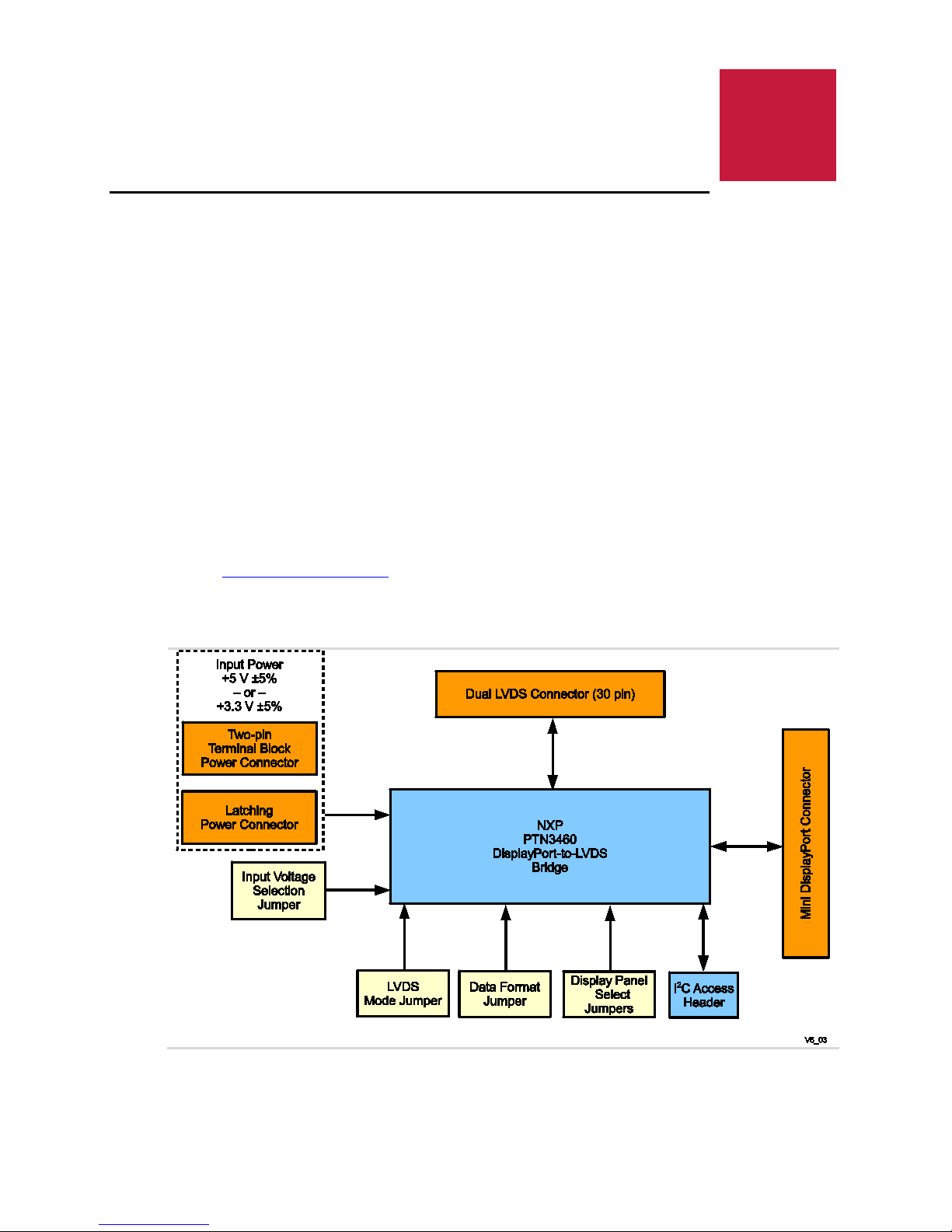
Figure 1. VL-EPH-V6 Block Diagram ............................................................................................................ 1
Figure 2. VL-EPH-V6 Dimensions and Mounting Holes ................................................................................ 3
Figure 3. VL-EPH-V6 Hardware Assembly .................................................................................................... 4
Figure 4. Connector Locations ........................................................................................................................ 5
Figure 5. Jumper Locations ........................................................................................................................... 10
Tables
Table 1: Connector Functions and Interface Cables ....................................................................................... 6
Table 2: J1 and J2 Power Input Connector Pinout ......................................................................................... 7
Table 3: LVDS Connector Pinout .................................................................................................................. 8
Table 4: J4 Mini DisplayPor t Co nnecto r Pinout............................................................................................. 9
Table 5: Jumper Configurat ions ................................................................................................................... 11
Table 6: LVDS Panel Types and Jumper Configurations ............................................................................. 12
Table 7: LVDS Panel Displays Tested with the EPH-V6 ............................................................................. 12
Table 8: LVDS Cables Available from VersaLo gic ..................................................................................... 13
VL-EPH-V6 Reference Manual iv
Page 5
1 1
Description
The VL-EPH-V6 module provides a rugged converter from standard mini-DisplayPort video
output to LVDS (Low Voltage Differential Signaling) display panel output. The VL-EPH-V6
enables system designers to utilize their existing LVDS video panels with the latest embedded
computer video output (mini-DisplayPort).
As with all VersaLogic products, the VL-EPH-V6 supports OEM applications where high
reliability and long-term availability are required. From application design-in support, to the 5+
year production life guarantee, and a full 5-year warranty, the VL-EPH-V6 provides reliable
video conversion for demanding applications.
The VL-EPH-V6 is compliant with both DisplayPort v1.2 and DisplayPort v1.1.
Introduction
Technical Specifications
See the VL-EPH-V6 Data Sheet for complete specifications.
Block Diagram
VL-EPH-V6 Reference Manual 1
Figure 1. VL-EPH-V6 Block Diagram
Page 6
Cautions
Electrostatic discharge (ESD) can damage circuit boards, disk drives, and other
not slide the board over any surface.
After removing the board from its protective wrapper, place the board on a grounded,
static-free surface, component side up. Use an antistatic foam pad if available.
The board should also be protected inside a closed metallic antistatic envelope during
shipment or storage.
All mounting standoffs should be connected to earth ground (chassis ground). This
provides proper grounding for EMI purposes.
ELECTROSTATIC DISCHARGE
EARTH GROUND REQUIREMENT
Introduction
CAUTION:
components. The circuit board must only be handled at an ESD workstation. If an
approved station is not available, some measure of protection can be provided by
wearing a grounded antistatic wrist strap. Keep all plastic away from the board, and do
CAUTION:
VL-EPH-V6 Reference Manual 2
Page 7

2 2
Dimensions and Mounting
Figure 2 shows the dimensions of the VL-EPH-V6.
Physical Details
Figure 2. VL-EPH-V6 Dimensions and Mounting Holes
(Not to scale. All dimensions in millimeters.)
VL-EPH-V6 Reference Manual 3
Page 8

Hardware Assembly
The VL-EPH-V6 can be secured to the host board using two hardware standoffs on the corner
mounting holes. These standoffs attach to the host using pan head screws. Standoffs and screws
are available as part number VL-HDW-105 (metric thread) or VL-HDW-106 (English thread).
Figure 3 shows a typical installation.
Physical Details
Figure 3. VL-EPH-V6 Hardware Assembly
VL-EPH-V6 Reference Manual 4
Page 9

J1
Power input connector
J2
Power input connector
J3
Dual-channel LVDS connector
J4
Mini DisplayPort connector
J5
Reserved
3 3
Interfaces and Connectors
Connector Locations
Reference Designator Description
Figure 4. Connector Locations
VL-EPH-V6 Reference Manual 5
Page 10

Connector Functions and Interface Cables
Connector
Function
Mating Connector
Transition Cable
Cable Description
Molex 22-05-3021
x2 crimp
(Note 2)
AWG
VL-CBR-3003
DisplayPort
—
—
Notes:
2. Use 16 AWG wire for this connector. This is particularly nec es sary if you are using a +3.3 V power source.
Table 1 provides information about the function, mating connectors, and transition cables for
VL-EPH-V6 connectors.
Table 1: Connector Functions and Interface Cables
Interfaces and Connectors
J1
J2
J3 LVDS JAE FI-X30HL-B
J4 Mini DisplayPort Mini DisplayPort
J5 Reserved —
1. Use 22 AWG wire for this connector
Power input
(Note 1)
Power input
housing, Molex 2759
Insulated wire, 16
— Customer designed
— 2-pin screw terminal
VL-CBR-3001
VL-CBR-3002
VL-CBR-2031
Refer to Table 8 on page 13
for more information on
these transition cables.
36” Mini DisplayPort to Mini
VL-EPH-V6 Reference Manual 6
Page 11

Power Input Connectors
A +5V input voltage must not be applied to the VL-EPH-V6 when 3.3V mode is selected.
Doing so will damage the board.
Connector J1 or J2 supplies input voltage to the VL-EPH-V6. Voltage is applied through one
connector only, not both. The VL-EPH-V6 accepts power input of either +5V ± 5% or
+3.3V ± 5%. Jumper block V1 selects the input voltage (see Jumpers on page 10).
CAUTION:
Connector J1 is a 2-pin header for use with a plug-in latching connector. This connector is
useful for lower current LVDS panels (in the 1-3 A range).
Connector J2 is a 2-pin screw terminal, useful for higher current panels (in the 3-4 A range).
Table 2 lists the pinout of the J1and J2 connectors and shows the location of pin 1 for both
connectors.
Table 2: J1 and J2 Power Input Connector Pinout
Interfaces and Connectors
Pin Signal Description
1 V_IN Power input
2 GND Ground
VL-EPH-V6 Reference Manual 7
Page 12

LVDS Interface
J3 Pin
Signal Name
Description
The VL-EPH-V6 provides a 30-pin, 1 mm pitch, dual-channel LVDS connector at location J3.
Table 3 lists the pinout of the LVDS connector. Table 6 (on page 12) lists the LVDS cables
available from VersaLogic.
Note: Backlight control is not supported in the VL-EPH-V6.
1 LVDS_ODD0_N LVDS Odd Lane 0 Negative Differential Signal
2 LVDS_ODD0_P LVDS Odd Lane 0 Positive Differential Signal
3 LVDS_ODD1_N LVDS Odd Lane 1 Negative Differential Signal
4 LVDS_ODD1_P LVDS Odd Lane 1 Positive Differential Signal
5 LVDS_ODD2_N LVDS Odd Lane 2 Negative Differential Signal
6 LVDS_ODD2_P LVDS Odd Lane 2 Positive Differential Signal
7 GND1 Signal/Power Ground
8 LVDS_ODDCLK_N LVDS Odd Clock Negative Differential Signal
9 LVDS_ODDCLK_P LVDS Odd Clock Positive Differential Signal
10 LVDS_ODD3_N LVDS Odd Lane 3 Negative Differential Signal
11 LVDS_ODD3_P LVDS Odd Lane 3 Positive Differential Signal
12 LVDS_EVEN0_N LVDS Even Lane 0 Negative Differential Signal
13 LVDS_EVEN0_P LVDS Even Lane 0 Positive Differential Signal
14 GND2 Signal/Power Ground
15 LVDS_EVEN1_N LVDS Even Lane 1 Negative Differential Signal
16 LVDS_EVEN1_P LVDS Even Lane 1 Positive Differential Signal
17 GND3 Signal/Power Ground
18 LVDS_EVEN2_N LVDS Even Lane 2 Negative Differential Signal
19 LVDS_EVEN2_P LVDS Even Lane 2 Positive Differential Signal
20 LVDS_EVENCLK_N LVDS Even Clock Negative Differential Signal
21 LVDS_EVENCLK_P LVDS Even Clock Positive Differential Signal
22 LVDS_EVEN3_N LVDS Even Lane 3 Negative Differential Signal
23 LVDS_EVEN3_P LVDS Even Lane 3 Positive Differential Signal
24 GND4 Signal/Power Ground
25 GND5 Signal/Power Ground
26 VCC1 Panel Power (5V or 3.3V)
27 GND6 Signal/Power Ground
28 VCC2 Panel Power (5V or 3.3V)
29 VCC3 Panel Power (5V or 3.3V)
30 VCC4 Panel Power (5V or 3.3V)
Interfaces and Connectors
Table 3: LVDS Connector Pinout
VL-EPH-V6 Reference Manual 8
Page 13

Mini DisplayPort Interface
1
2
3
4
5
6
7
8
9
10
11
12
13
14
17
18
19
20
Note:
resistor.
The VL-EPH-V6 uses a Mini DisplayPort “Sink” interface at J4 to interface with the host
computer Mini DisplayPort “Source” connector. VersaLogic cable VL-CBR-2031 provides the
Mini DisplayPort to Mini Display port connection.
DisplayPort consists of the following interfaces:
Main Link – transfers high speed isochronous video and audio data.
Auxiliary channel – used for link management and device control. The Extended Display
Identification Data (EDID) is read over this interface.
Hot Plug Detect – this signal alerts the PCH when a device is connected.
The VL-EPH-V6 supports Main DP Link operation with one or two lanes. Table 4 lists the
pinout of the VL-EPH-V6 Mini DisplayPort connector.
Table 4: J4 Mini DisplayPort Connector Pinout
Interfaces and Connectors
Pin Signal Name
GND
No connect
No connect
GND
No connect
No connect
GND
15
ML_LANE1_P
ML_LANE1_N
GND
This signal is tied to ground through a 10 kΩ pull-down
Pin Signal Name
HOT PLUG DETECT
CONFIG 1 (Note)
CONFIG 2 (Note)
GND
ML_LANE0_P
ML_LANE0_N
GND
16
AUX_CH_P
AUX_CH_N
No connect
VL-EPH-V6 Reference Manual 9
Page 14

Jumpers
V1
Input voltage selection jumper
V2
LVDS mode jumper
V3
Data format and color depth jumper
V4
Reserved
V5
Reserved
V6
Panel type select jumper
V7
Panel type select jumper
appear.
Figure 5 shows the locations of the jumper blocks. Table 5 lists the functions and configurations
of the jumper blocks.
Interfaces and Connectors
Reference Designator Description
Figure 5. Jumper Locations
Integrator’s Note:
Set the input voltage selection jumper (V1) first.
Set the panel configuration jumpers (V2, V3, V6, and V7) before connecting a display panel
to the EPH-V6.
If any of the panel configuration jumpers are not properly set for the display device, no image will
VL-EPH-V6 Reference Manual 10
Page 15

Table 5: Jumper Configurations
3
2
1
V1
3
2
1
V1
3
2
1
V1
3
2 1
V3
3
2
1
V3
3
2 1
V3
1
2
V2
1
2
V2
V6
V7
2 12 1 2 1
V6
V7
2 12 1
V6
V7
2 12 1
V6
V7
2 1
2 1
Function Jumper Position Configuration
Input voltage is +5V ±5%
Engages circuitry that protects
components that require +3.3V.
(This is the as-shipped configuration)
Input voltage is +3.3V ±5%
Input voltage selection
(Jumper V1)
CAUTION: A +5V input voltage must not
be applied to the VL-EPH-V6 when 3.3V
mode is selected. Doing so will damage
the board.
Logic circuits are not powered
JEIDA or VESA data format
Color depth = 18 bits per pixel (bpp)
(This is the as-shipped configuration)
Interfaces and Connectors
Data format and color
depth selection
(Jumper V3)
LVDS mode
(Jumper V2)
Panel Type select
(Jumpers V6 and V7)
VESA data format
Color depth = 24 bpp
JEIDA data format
Color depth = 24 bpp
Single-channel LVDS
(This is the as-shipped configuration)
Dual-channel LVDS
These jumpers configure the EPH-V6 for
use with one of four specific types of
LVDS panel displays.
For information on the supported display
panel types, refer to
Table 6 on page 12.
VL-EPH-V6 Reference Manual 11
Page 16

Characteristics
Signal Cable
Power Cable
800 x 600 (SVGA)
V6
V7
2 1
2 1 2 1
1024 x 768 (XGA)
V6
V7
2 1
2 1
1280 x 800 (WXGA)
V6
V7
2 12 1
1920 x 1080 (HD 1080)
V6
V7
2 12 1
Configure the V6 and V7 jumpers before connecting a display panel to the EPH-V6. If any of the
configuration jumpers are not properly set for the display device, no image will appear.
Signal Cable
4 4
Display Panels and Cables
Configuring the Board for an LVDS Panel
The panel type select jumpers (V6 and V7) configure the EPH-V6 for the display device. When
choosing a display device, match the characteristics of your selection to the data in the first
column of Table 6. Set the panel type selection jumpers (V6 and V7) to match your display
device’s characteristics.
Table 6: LVDS Panel Types and Jumper Configurations
Supported Panel
Single channel
18/24 bit
Single channel
18/24 bit
LVDS
VL-CBR-3003 VL-CBR-0601
VL-CBR-3002 VL-CBR-0601
Backlight
Single channel
18/24 bit
Dual channel
16.7M colors
VL-CBR-3002 VL-CBR-0601
VL-CBR-3001 –––
Integrator’s Note:
LVDS Panel Displays Tested with the EPH-V6
Table 7 lists the LVDS panel displays tested with the EPH-V6.
V6/V7 Jumper Settings
Table 7: LVDS Panel Displays Tested with the EPH-V6
Manufacturer Model Number Display Resolution Display Size
Sharp LQ121S1LG42 800×600 SVGA 12.1 inches (31 cm) VL-CBR-3003
Sharp LQ150X1LG91 1024x768 XGA 15 inches (38 cm) VL-CBR-3002
Sharp LQ121K1LG52LCD 1280x800 (WXGA) 12.1 inches (31 cm) VL-CBR-3002
LG LM230WF3-SLD1 1920x1080 (HD 1080) 23 inches (58.4 cm) VL-CBR-3001
VL-EPH-V6 Reference Manual 12
LVDS
Page 17

LVDS Cables Available from VersaLogic
VersaLogic Part Number
Length
Channels
Function
Table 8: LVDS Cables Available from VersaLogic
Display Panels and Cables
VL-CBR-3001 20 inches 2
VL-CBR-3002 20 inches 1
VL-CBR-3003 20 inches 1
30-pin JAE to 30-pin JAE
30-pin JAE to 20-pin Hirose
30-pin JAE to 20-pin JAE
VL-EPH-V6 Reference Manual 13
 Loading...