

Page 1

Reference
Reference
ReferenceReference
Manual
Manual
ManualManual
VL-586-1
5x86 Industrial CPU Card
for the STD 32 Bus
TM
Page 2

Page 3

VL-586-1
5x86 Industrial CPU Card
for the STD 32 Bus
TM
M586-1
Page 4

Page 5

VL-586-1
5x86 Industrial Computer
for the STD 32 Bus
REFERENCE MANUAL
Doc. Rev. 10/01/2003
(for VL-586-1 Rev. 3)
V
ERSALOGIC CORPORATION
WWW.VERSALOGIC.COM
Notice:
Although every effort has been made to ensure this document is error-free, VersaLogic makes no
representations or warranties with respect to this product and specifically disclaims any implied
warranties of merchantability or fitness for any particular purpose.
VersaLogic reserves the right to revise this product and associated documentation at any time
without obligation to notify anyone of such changes.
3888 Stewart Road
Eugene, OR 97402
(541) 485-8575
Fax (541) 485-5712
Contents Copyright ©2000
All Rights Reserved
Page 6

Page 7

Table of Contents
Other References ...............................................................................................................vi
1. Overview ....................................................................................................................1
Using This Manual ............................................................................................................. 1
Introduction ........................................................................................................................ 1
PC/AT Compatibility............................................................................................. 1
STD/STD32 Bus Compatibility............................................................................. 2
PC/104-Plus Compatibility ................................................................................... 2
On-Board Memory ................................................................................................ 2
Hard Disk and Floppy Disk Interface.................................................................... 2
Serial Ports............................................................................................................. 2
Parallel Port ...........................................................................................................3
Counter/Timers...................................................................................................... 3
Real Time Clock with CMOS RAM ..................................................................... 3
Interrupt Controllers .............................................................................................. 3
DMA Controllers................................................................................................... 3
Watchdog Timer .................................................................................................... 3
Technical Specifications..................................................................................................... 4
Technical Support...............................................................................................................5
Repair Service........................................................................................................ 5
2. DOS Based Quick Start.............................................................................................7
Introduction ........................................................................................................................ 7
Installation .......................................................................................................................... 8
Jumper Locations................................................................................................................9
Card Installation ...............................................................................................................10
Monitor Installation .......................................................................................................... 11
Cable Installation..............................................................................................................12
CMOS RAM Setup........................................................................................................... 12
CMOS Setup Options ....................................................................................................... 13
Main CMOS Setup Menu .................................................................................... 13
Basic CMOS Configuration................................................................................. 13
Advanced Configuration...................................................................................... 13
Shadow Configuration......................................................................................... 13
Reset CMOS to Last Known Values ................................................................... 13
Reset CMOS to Factory Defaults ........................................................................ 14
Write to CMOS and Exit ..................................................................................... 14
Exit Without Changing CMOS............................................................................ 14
Clearing the CMOS RAM ................................................................................................ 15
3. Configuration...........................................................................................................17
Hardware Jumper Summary ............................................................................................. 17
Jumper Block Locations ...................................................................................... 18
iii
Page 8

Table of Contents
Memory Configuration ..................................................................................................... 22
ROM Configuration............................................................................................. 22
DRAM Configuration.......................................................................................... 22
CMOS RAM Configuration ................................................................................ 23
Battery Backed SRAM Configuration................................................................. 23
Memory Map ....................................................................................................... 24
I/O Configuration ............................................................................................................. 25
Using 8-Bit STD Bus I/O Cards .......................................................................... 25
Using 10-Bit STD Bus I/O Cards ........................................................................ 25
Using 16-Bit STD Bus I/O Cards ........................................................................ 26
Using PC/104 Modules........................................................................................ 26
I/O Map................................................................................................................ 27
COM2 Configuration........................................................................................................ 28
RS-232 Operation ................................................................................................ 28
RS-422 Operation ................................................................................................ 28
RS-485 Operation ................................................................................................ 28
Multiprocessor Configuration .......................................................................................... 30
Multiprocessor Jumper Configuration................................................................. 30
Resistor Pack Configuration................................................................................ 31
Multiprocessor CPU Reset ..................................................................................31
Interrupt Configuration..................................................................................................... 32
Interrupt Configuration Jumpers .........................................................................33
STD Bus Interrupt Signals................................................................................... 34
CPU Interrupt Request Inputs.............................................................................. 35
Interprocessor Communications Interrupt Configuration ................................... 37
Non-maskable Interrupt Configuration ...............................................................37
4. Installation ...............................................................................................................39
Introduction ...................................................................................................................... 39
Card Insertion and Extraction........................................................................................... 40
Card Installation .................................................................................................. 40
Card Placement.................................................................................................... 40
STD 80 Bus Installation Guidelines .................................................................... 40
STD 32 Bus Installation Guidelines .................................................................... 40
External Connections........................................................................................................ 41
Connector Functions............................................................................................ 41
Connector Locations............................................................................................ 41
High Density 100-Pin Connector ........................................................................ 42
JA, JE – Serial Port Connectors........................................................................... 43
JB – LPT1 Parallel Port Connector .....................................................................44
JC – Counter/Timer ............................................................................................. 45
JD – Keyboard Connector ................................................................................... 46
JF – Hard Disk Drive Connector ......................................................................... 47
J2 – Interrupt Connector...................................................................................... 48
J3 – Floppy Disk Drive Connector ...................................................................... 49
L1 – Speaker Connector ...................................................................................... 50
iv
Page 9

Table of Contents
5. Register Descriptions .............................................................................................51
Introduction ...................................................................................................................... 51
Register Summary ............................................................................................................ 51
Direct Memory Access — Channel 1.................................................................. 52
Direct Memory Access — Channel 2.................................................................. 53
Direct Memory Access — Page Registers .......................................................... 53
COM1 Serial Port ................................................................................................ 54
COM2 Serial Port ................................................................................................ 54
LPT1 Parallel Port ............................................................................................... 55
Floppy Disk Drive Controller.............................................................................. 56
IDE Hard Disk Drive Controller ......................................................................... 56
Interrupt Controller — Master............................................................................. 57
Interrupt Controller — Slave............................................................................... 57
Counter/Timers.................................................................................................... 58
Miscellaneous ...................................................................................................... 58
Special Control Register...................................................................................... 59
Watchdog Timer Hold-Off Register.................................................................... 60
I/O and Memory Map Control Register .............................................................. 61
Map and Paging Control Register ....................................................................... 62
Appendix A — Schematic ...........................................................................................63
Index.............................................................................................................................72
v
Page 10

Other References
Acer Laboratories Inc., (408) 764-0644, http://www.ali.com.tw
M1489 / M1487 486 PCI Chipset Data Book
Chips and Technologies, Inc., (408) 434-0600, http://www.chips.com
82C735 Super I/O Chip Data Book
STD 32 Manufacturers Group, (800) 733-2111, http://www.std32.com
STD 32 Bus Specification and Designer’s Guide
Advanced Micro Devices (800) 222-9323, http://www.amd.com
AM486DX5-133V17BHC Data Book
Additional Resources,
http://www.annatechnology.com
http://www.annatech/bookBrowseBySubjectF.asp
Other References
vi
Page 11

Using This Manual
Each chapter in this manual corresponds to a step in the installation process:
Chapter 1 – Overview
Lists basic information about the CPU card, specifications, and system requirements. Use
this chapter to familiarize yourself with the card and it’s capabilities.
Chapter 2 – DOS Based Quick Start
Describes how to quickly get your DOS based system set up and running using a VL-586-1
CPU card.
Chapter 3 – Configuration
Describes how to jumper the CPU card.
Chapter 4 – Installation
Describes how to install the VL-586-1. It also provides details on the external connections.
Chapter 5 – Register Descriptions
Overview
1
Provides details about the user-programmable registers on the CPU card.
Appendix A – Schematics
Circuit diagrams.
Introduction
The VL-586-1 CPU card is fully PC hardware compatible, and features a 32-bit, 133 MHz,
Am5x86 microprocessor, up to 32MB RAM, 512K or 2.5MB Flash, two COM ports, one LPT
port, six counter/timers, and real time clock. The card supports all operating systems designed to
execute on PC hardware (DOS, Windows 95, QNX, etc.) and can be expanded using STD/STD
32 Bus I/O cards or by plugging PC/104 or PC/104-Plus expansion modules directly onto the
VL-586-1 circuit card.
PC/AT C
Standard I/O and peripheral interfaces, including BIOS, Embedded DOS, and a bootable Flash
Disk System bring a diskless embedded PC to the STD Bus form factor.
OMPATIBILITY
VL-586-1 Reference Manual Overview – 1
Page 12

Introduction
STD/STD32 B
US COMPATIBILITY
The VL-586-1 CPU card complies with certain subsets of the STD 32 Bus specification that
allow it to communicate with STD 80 compatible 8-bit and STD 32 compatible 16-bit I/O and
memory cards. In addition, the card fully complies with the STD 80 Bus specification using a
bus speed of 8.33 MHz. The CPU card is compatible with all I/O and memory cards that adhere
to STD 80 specifications.
PC/104-P
LUS COMPATIBILITY
The VL-586-1’s PC/104-Plus expansion site allows PC/104 and PC/104-Plus modules to be
stacked directly on the board. This permits the use of high speed video modules and "local" I/O
expansion in systems using multiple processor cards. Use of on-board modules requires an
empty card slot space next to the VL-586-1 board. Both standard PC/104 and PC/104-Plus (PCI
32-bit, 33 MHz) based modules are supported.
N-BOARD MEMORY
O
DRAM
The on-board DRAM socket (U11) accepts one standard 72-pin SO DIMM module. A
variety of sizes may be used (16M, 32M or 64M.) Fast Page Mode and EDO type modules are
supported, provided they are 70ns or faster. Both 5V or 3.3V modules can be used (jumper
selectable.)
BBSRAM
The (-p) version of the VL-586-1 includes 512K of on-board Battery-Backed Static
RAM for non-volatile storage of information. This RAM is accessible through a 64K page frame
at E0000h in the main memory map.
CMOS RAM
FLASH
or 32 pin J-lead ceramic part(s). A Flash Disk System and Embedded DOS are included
PLCC
Standard setup values are stored in a small battery-backed CMOS RAM chip.
The VL-586-1 on-board ROM socket (U3) accepts 128Kx8 or 512Kx8, 32 pin plastic
which allow the card to boot to the A: prompt without user configuration.
ARD DISK AND FLOPPY DISK INTERFACE
H
A 40-pin IDE hard disk drive interface supports modes 1 through 4 via a PCI based controller. A
34-pin floppy disk drive interface is also included on the VL-586-1 card for connection to
industry standard 3½" floppy drives. Each interface supports two drives, and will work with
externally mounted or in-rack devices.
ERIAL PORTS
S
The two on-board serial ports are hardware and software compatible with 16550 type UARTs
with 16 byte FIFOs. Baud rates are programmable from 50 baud to 115K baud. COM1 is a
standard RS-232 interface, COM2 can be jumpered for RS-232, RS-422, or RS-485 operation.
2 – Overview VL-586-1 Reference Manual
Page 13

Introduction
ARALLEL PORT
P
The parallel port can be used as a standard bi-directional/ECP/EPP compatible LPT port or as 17
general purpose TTL I/O signals. When operating in standard bi-directional mode, each output
line has a 24 ma current sink rating. Eight of the signals are programmable as a group for input
or output, three are dedicated output, and five are dedicated inputs. A strobe signal, which
produces a 50 µs pulse under program control, is also available as an output.
OUNTER/TIMERS
C
The VL-586-1 card includes six 8254 type 16-bit counter/timers. Three channels are used by the
operating system; one channel is reserved for dynamic
refresh, one channel generates an
RAM
18.2 ms DOS interrupt, and another channel is used to drive the speaker. The remaining three
channels are unallocated, and can be clocked with on-board crystal oscillators or from external
inputs.
EAL TIME CLOCK WITH
R
CMOS RAM
A battery-backed 146818 compatible real time clock (RTC) provides accurate date and time
functions. This PC/AT compatible RTC also contains 128 bytes of battery-backed CMOS RAM
with 114 bytes available as a system resource to store standard setup parameters. Normally the
BIOS requires 94 bytes, leaving 20 bytes for general purpose use.
NTERRUPT CONTROLLERS
I
Two PC AT compatible 8259 type programmable interrupt controllers (PICs) are provided for
full DOS functionality. Interrupt sources and destinations can be configured with jumper blocks.
Interrupt lines connect to on-card sources, STD/STD 32, PC/104, and PCI Bus sources, and to a
user connector.
DMA C
ONTROLLERS
The VL-586-1 has two DMA controllers which provide a total of eight DMA channels (four 8-bit
channels and four 16-bit channels.) DMA control signals for seven channels are available on the
PC/104 Bus. The remaining 16-bit channel is accessible only by software. DMA control signals
are not available on the STD Bus, PCI Bus, or via front plane connector.
ATCHDOG TIMER
W
A Dallas 1232 watchdog timer circuit provides a degree of protection against hardware and
software failures. When the watchdog timer is enabled, it must be periodically updated by
software at least every 250 ms minimum. A system failure which prevents updating will reset the
CPU. This same circuit monitors the +5V power, and handles a variety of CPU reset functions.
VL-586-1 Reference Manual Overview – 3
Page 14

Technical Specifications
Technical Specifications
Specifications are typical at 25°C with 5.0V supply unless otherwise noted.
Size:
Meets all STD 80 and STD 32 Bus mechanical specifications
Storage Temperature:
-40 °C to 85 °C
Free Air Operating Temperature:
0 °C to 65 °C
Power Requirements:
5V ±5% @ 1570 ma
(±12V may be required by add-on PC/104 I/O modules)
System Reset:
Vcc sensing, resets below 4.7V
Watchdog reset (jumper option)
LPT1/Parallel Interface:
Data Lines:
Output low voltage: 0.5V @ 24 ma
Output high voltage: 2.4V @ -12 ma
Control Lines:
Output low voltage: 0.5V @ 24 ma
Output high voltage: 2.4V @ -150 µA
COM1 & COM2 Serial Interfaces:
COM2 configurable as RS-232/422/485
Floppy Disk Drive Interface:
Supports two drives.
Hard Disk Drive Interface:
Supports two EIDE drives.
Memory Sockets:
DRAM:
16, 32 or 64 MB system dynamic RAM in one 72-pin SO DIMM gold plated socket
SRAM: (battery backed on board)
128K / 512K byte battery backed static RAM in a JEDEC compatible 32-pin SOP site
Flash:
128K to 2.5 MB (64K paged)
One 32-pin PLCC socket and one 48-pin TSOP site
Memory Speed: (on-board):
RAM: 70 ns
Flash: 200 ns or faster
Bus Compatibility:
STD 80: Full compliance, 8.33 MHz bus speed
STD 32: Permanent Master, SA16, SA8 I, MB, MX
STD 32: Temporary Master, SA16, SA8 I, MB, {MX}
PC/104: Full compliance
PC/104-Plus: Full compliance
(with 8 MB DRAM, 512 K Flash, 512 K SRAM, Keyboard)
Specifications are subject to change without notice.
4 – Overview VL-586-1 Reference Manual
Page 15

Technical Support
If you have problems that this manual can’t help you solve, contact VersaLogic for technical
support at (800) 824-3163 or (541) 485-8575. You can also reach VersaLogic by e-mail at
info@versalogic.com.
EPAIR SERVICE
R
If your product requires service, you must obtain a Returned Material Authorization (RMA)
number by calling (800) 824-3163.
Please provide the following information:
• Your name, the name of your company, and your phone number
• The name of a technician or engineer who we can contact if we have questions
• Quantity of items being returned
• The model and serial number of each item (the serial number is a 5 digit bar code)
Technical Support
• A description of the problem
• Steps you have taken to resolve or repeat the problem
• The return shipping address
Warranty Repair All charges are covered, including UPS 3rd Day Select shipping
charges for return back to your facility.
Non-warranty Repair All non-warranty repairs are subject to diagnosis and labor charges,
parts charges, and return shipping fees. We will need to know what
shipping method you prefer for return back to your facility, and we
will need to secure a purchase order number for invoicing the repair.
Note! Please mark the RMA number clearly on the outside of the box before
returning.
Send To VersaLogic Corporation
3888 Stewart Rd
Eugene, OR 97402
VL-586-1 Reference Manual Overview – 5
Page 16

Page 17

This chapter describes how to quickly get your DOS-based system set up and running using the
VL-586-1 CPU card
Introduction
A minimum DOS based run time system requires the CPU card, a BIOS, and a boot device
containing an operating system and an application program. In many cases a video card,
keyboard, and monitor are added to this list, however, the VL-586-1 does not demand their
presence in order to boot.
The VL-586-1 includes a Flash Disk System and an installed bootable copy of Embedded DOS.
If you require a DR-DOS disk call 1-541-485-8575 and we will send one free of charge. The
CMOS RAM information is shipped in its factory default condition, which allows immediate
booting to the command prompt. If the CMOS Setup parameters need to be changed, the most
convenient method of setting up this information is by using a keyboard and monitor. This
requires the addition of a video card.
Typical components of a VL-586-1 DOS based system include:
• VL-586-1 CPU Card
DOS Based Quick Start
2
• STD or STD 32 Card Cage
• Standard PC/AT keyboard
• PC/104 Video Module
• Video Monitor
• Keyboard
• Power Supply
VL-586-1 Reference Manual DOS Based Quick Start – 7
Page 18

Installation
Installation
Caution Electrostatic discharge (ESD) can damage cards, disk drives, and other
components. Do the installation procedures described in this chapter only at an
ESD workstation. If such a station is not available, you can provide some ESD
protection by wearing an antistatic wrist strap and attaching it to a metal part on
the card cage.
Cards can be extremely sensitive to ESD and always require careful handling.
After removing the card from its protective wrapper or from the card cage, place
the card on a grounded, static-free surface, component side up. Use an anti-static
foam pad if available, but not the card wrapper. Do not slide the card over any
surface.
The card should also protected during shipment or storage with anti-static foam or
bubble wrap. To prevent damage to the lithium battery, do not use black
conductive foam or metal foil.
Warning! The lithium battery may explode if mistreated. Do not recharge, disassemble, or
dispose of in fire. Dispose of used batteries promptly.
8 – DOS Based Quick Start VL-586-1 Reference Manual
Page 19
Jumper Locations
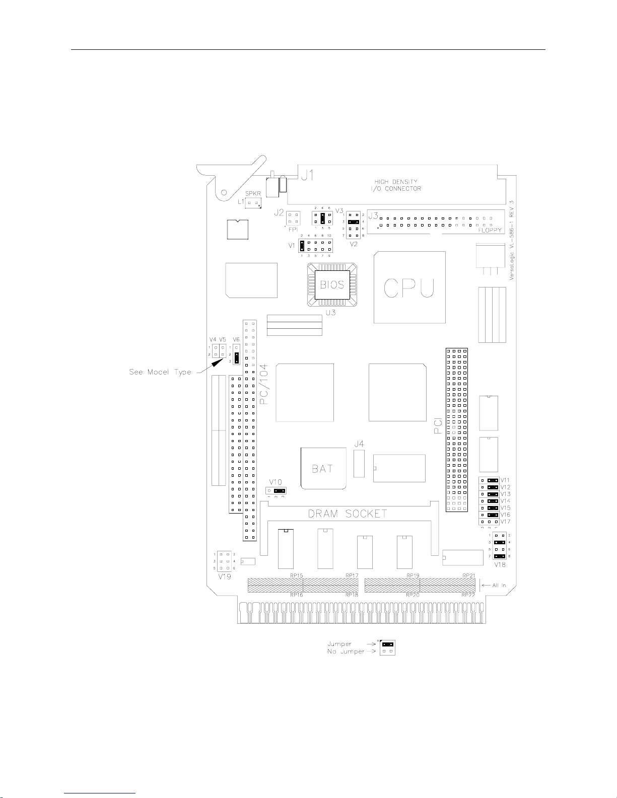
Note Jumpers and resistor packs shown in as-shipped configuration.
Jumper Locations
VL-586-1 Reference Manual DOS Based Quick Start – 9
Figure 1. VL-586-1 CPU Card Layout
Page 20

Card Installation
Card Installation
A typical development system consists of a six-slot V32-06T Card Cage, populated with:
• VL-586-1 CPU Card (with attached EPM-SVGA PC/104-Plus Video Module)
• IDE Hard Disk Drive
• Floppy Disk Drive
A VGA compatible monitor and a PC/AT compatible keyboard are also required to complete the
set of hardware necessary for development purposes.
Warning! To prevent damage, cards should be inserted in and removed from the card cage
only when the system power is off.
Caution To avoid damaging cards, they must be oriented correctly (usually with the card
ejector toward the top of the card cage.) Refer to the card cage documentation for
the correct way to insert STD/STD 32 Bus cards.
10 – DOS Based Quick Start VL-586-1 Reference Manual
Page 21
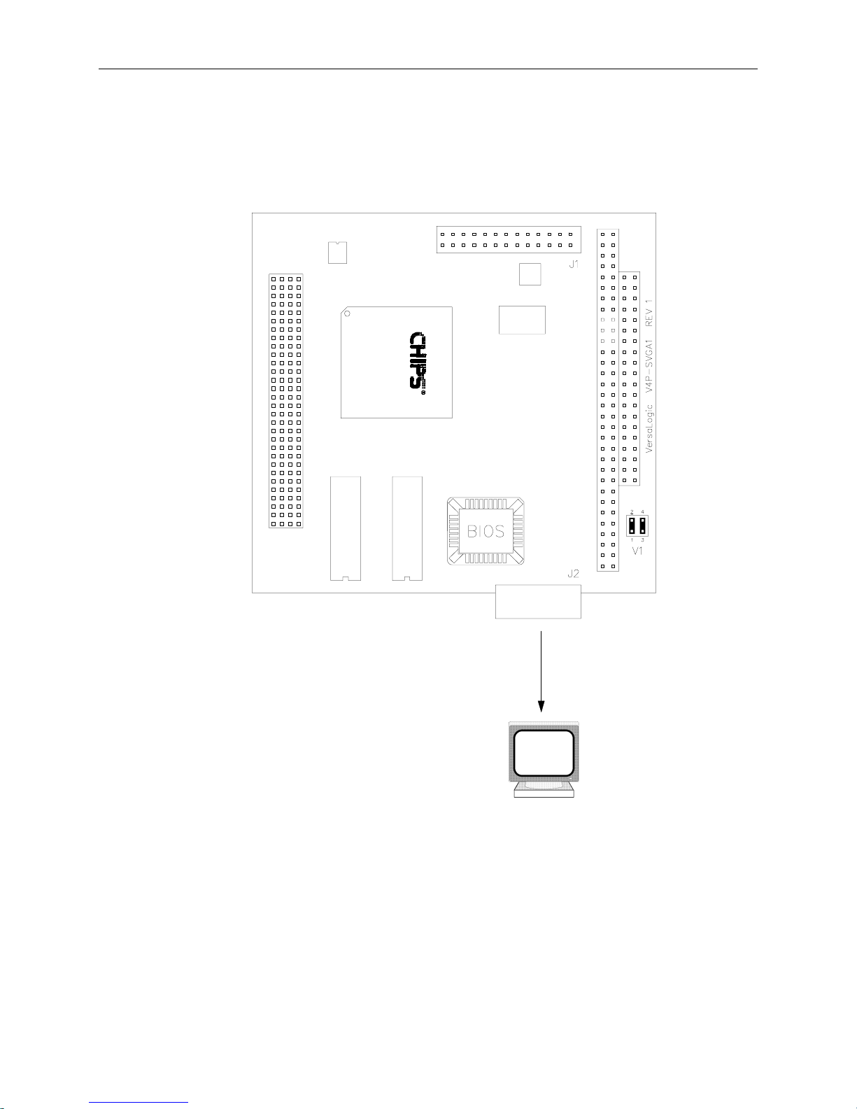
Monitor Installation
A VGA monitor should be connected to the EPM-SVGA module as shown .
Monitor Installation
Figure 2. Jumpers/Connections for an EPM-SVGA Using a VGA Monitor
VL-586-1 Reference Manual DOS Based Quick Start – 11
Page 22

Cable Installation
Cable Installation
To bring the header connectors on the VL-586-1 CPU card out to industry standard PC pinouts,
the VersaLogic cable VL-CBL-100A is used.
CMOS RAM Setup
The VL-586-1 CPU card uses battery-backed, non-volatile CMOS RAM provided by the real
time clock chip to store system configuration settings. You can change these system settings with
the Setup program (accessed manually during system boot.) The configuration information is
read by the CPU upon system reset.
The Setup program is permanently stored in ROM, and can be run with or without an operating
system present. To run Setup, reset the CPU card and press the DEL key when prompted.
Select “BASIC CMOS CONFIGURATION” to display a summary of the information stored in
the CMOS RAM. To change the values shown, use the cursor arrows to move the highlight bar
to the desired entry field and press the – or + keys to change the values.
When you are finished, exit to the main Setup menu and select “WRITE TO CMOS AND
EXIT” to save the changes and exit the Setup program. The CPU will then boot from the onboard Flash Disk System (drive A:).
12 – DOS Based Quick Start VL-586-1 Reference Manual
Page 23
CMOS Setup Options
CMOS Setup Options
M
ASIC
B
AIN
CMOS S
CMOS C
ETUP MENU
SYSTEM BIOS SETUP - UTILITY VERSION 2.001.xxx
(C) 1994-1996 VERSALOGIC, CORP. ALL RIGHTS RESERVED
Basic CMOS Configuration
Advanced Configuration
Shadow Configuration
Format Integrated Flash Disk
Reset CMOS to last known values
Reset CMOS to factory defaults
Write to CMOS and Exit
Exit without changing CMOS
<ESC> TO CONTINUE (NO SAVE)
ONFIGURATION
This option goes to another menu which allows you to change the following:
• Date, Time
• Drive assignments and types
• Boot sequence
• Keyboard Parameters
• Memory Tests
A
DVANCED CONFIGURATION
This option goes to another menu which allows you to change the following:
• Bus Timing
• Memory and I/O Mapping
• Cache Control
S
HADOW CONFIGURATION
This option allows you to change ROM shadowing parameters.
ESET
R
CMOS
TO LAST KNOWN VALUES
This option acts like an undo function. It reverts all changes made in the CMOS Setup Screens to
the values they had when Setup was first entered.
VL-586-1 Reference Manual DOS Based Quick Start – 13
Page 24

CMOS Setup Options
ESET
R
CMOS
TO FACTORY DEFAULTS
This option overwrites all information contained in the CMOS RAM with predefined parameters
stored in the BIOS ROM, and reboots the CPU card.
The following parameters are loaded into CMOS RAM when this option is selected:
Basic CMOS Configuration
+---------------------------------------+--------------------------------------+
| Base Memory : 640 | Date (month day year) : Jan 01, 1997 |
| Extended Memory : 15360 | Time (hours:min:sec) : 00 : 00 : 00 |
| Drive A: type : Flash Disk +--------------------------------------+
| Drive B: type : Not installed Cyln Heads WPcom LZone Sect Size |
| Hard disk C: type : Not installed |
| Hard disk D: type : Not installed |
| --------------------------------------+--------------------------------------+
| 1st Boot Device : Mfg Mode | Seek Floppy at Boot : Enabled |
| 2nd Boot Device : Drive A: | Seek Hard Drive At Boot : Enabled |
| QNX FFS Extension : Disabled | |
| | Display "Hit <Del>..." : Enabled |
| | System Configuration Box : Enabled |
| Typematic Keys : Enabled | Wait for F1 on Error : Enabled |
| Typematic Delay : 250 ms | NumLock State at Boot : Disabled |
| Typematic Rate : 30 cps | |
| Memory Test Tick : Enabled | On-board IDE controllers : Enabled |
| Test Above 1MB : Enabled | PC/104 Video Shadowing : Enabled |
+---------------------------------------+--------------------------------------+
Advanced Configuration
+----------------------------------------+---------------------------------------+
| AT Bus Clock : CPUCLK/4 | Fast PC/104 Cycle : Enabled |
| DMA Clock : AT Clk/2 | Fast PCI Memory Cycle : Enabled |
| 16 bit PC/104 Wait States : None | CPU->PCI Write Buffer : Enabled |
| PC/104 I/O Recovery : Enabled | CPU->PCI Write Buff. Merge : Enabled |
| PC/104 I/O Recovery Time : 24*ATClk | CPU->PCI Write Buff. Burst : Enabled |
| DRAM Read Timing : Normal | CPU->PCI Fast Back-to-Back : Enabled |
| DRAM Write Timing : Normal | PCI->CPU Read Buffer : Enabled |
| 32-Bit PCI BIOS Extension : Enabled | PCI->CPU Write Buffer : Enabled |
| Reserved : Not Used | PCI->CPU Write Buff. Burst : Enabled |
| Reserved : Not Used | Internal Cache : Enabled |
| Slot 1 Using INT# : INT A | PCI INT A -> IRQ# : IRQ 15 |
| Slot 2 Using INT# : INT B | PCI INT B -> IRQ# : IRQ 12 |
| Slot 3 Using INT# : INT C | PCI INT C -> IRQ# : IRQ 11 |
| Slot 4 Using INT# : INT D | PCI INT D -> IRQ# : IRQ 10 |
| Route COM3:3E8h COM4:2E8h : PC/104 | Route I/O 0100h-027Fh : PC/104 |
| Route Memory D0000-D7FFFh : PC/104 | Route Memory C8000-CFFFFh : PC/104 |
| | |
+----------------------------------------+---------------------------------------+
RITE TO
W
CMOS
AND EXIT
This option updates the CMOS RAM with the information in the CMOS Setup Screens. After
writing, the CMOS checksum is updated and the CPU card is rebooted.
XIT WITHOUT CHANGING
E
CMOS
This option acts like a cancel function. Use it to exit Setup without changing CMOS RAM.
14 – DOS Based Quick Start VL-586-1 Reference Manual
Page 25
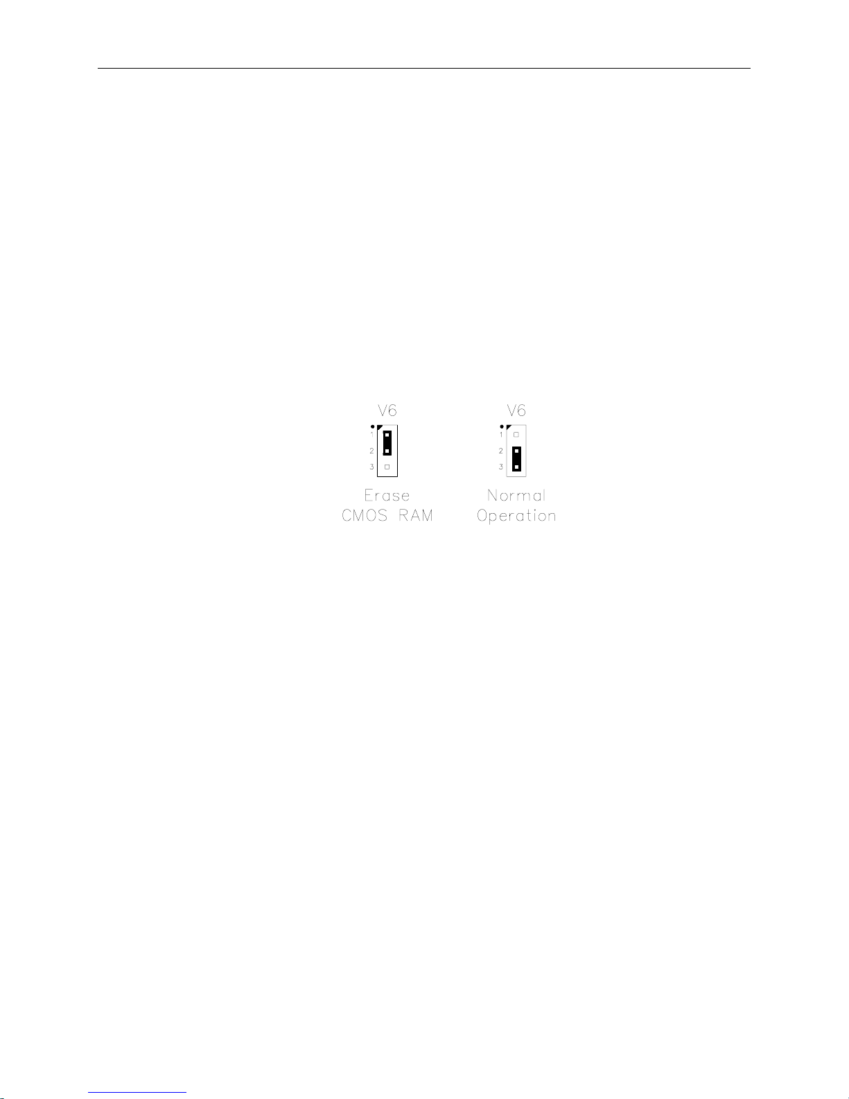
Clearing the CMOS RAM
Jumper V6[1-2] allows you clear the CMOS RAM contents if you remove the battery, install
incorrect setup information, or otherwise corrupt CMOS RAM. To ensure integrity of the CMOS
RAM, the Setup program calculates and stores an internal checksum of the setup data. Upon
reset, the CPU detects if the CMOS RAM is corrupted by analyzing the checksum. If you wish to
completely clear the contents of the CMOS RAM, briefly move jumper V6 to position [1-2] (top
position) then back to the position [2-3] (lower position) and reboot the system. This process will
load the factory default setup parameters into the CMOS RAM.
Warning! Do not apply power to the CPU card with jumper V6[1-2] installed, doing so may
damage the chipset and void the warranty. Jumper V6[1-2] is only briefly used to
clear the CMOS RAM.
Clearing the CMOS RAM
Figure 3. CMOS RAM Jumper
VL-586-1 Reference Manual DOS Based Quick Start – 15
Page 26

Page 27

This chapter describes how to configure the on-board options for the VL-586-1 CPU card.
Configuration involves both hardware (jumper) and software (CMOS Setup) configuration. The
jumpers configure the circuitry on the card for various modes of operation. The CMOS Setup
configuration completes the process by establishing default operating conditions.
Hardware Jumper Summary
Hardware option configuration is accomplished by installing or removing jumper plugs. In this
chapter, the term “in” is used to indicate an installed jumper and “out” is used to indicate a
removed jumper.
Use the following key to interpret the jumper diagrams used in this manual:
Figure 4. Jumpering Key
Configuration
3
VL-586-1 Reference Manual Configuration – 17
Page 28

Hardware Jumper Summary
UMPER BLOCK LOCATIONS
J
Note Jumpers and resistor packs shown in as-shipped configuration.
18 – Configuration VL-586-1 Reference Manual
Figure 5. Jumper Block Locations
Page 29

Table 1: Jumper Summary
Hardware Jumper Summary
Jumper
Block
V1[1-2] RS-232 Signal Enable
V1[3-4] RS-422/485 Ground Circuit
V1[5-6] RS-232/422/485 Mode Selector
V1[7-8] RS-422/485 Differential Line Driver Control
V1[9-10] RS-422/485 Transmission Line Termination
V2 Counter/Timer 5 Clock Source
Description
In — RS-232 mode. Enables the RS-232 line drivers and receivers.
Out — RS-422/485 mode. Disables the RS-232 line drivers and receivers.
In — RS-422/485 mode. Connects ground to J1 pin 6A.
Out — RS-232 mode. Frees J1 pin 6A for CTS2 (COM2).
In — RS-422/485 mode.
Out — RS-232 mode.
In — RS-485 mode. Enables software control of the differential line driver.
Out — RS-422 mode. Permanently enables the differential line driver.
In — Terminates data circuit with 100 Ω resistor
(RS-422, or RS-485 endpoint stations only)
Out — Leaves data circuit unterminated
(RS-485 intermediate multidrop stations only)
250 kHz 1 MHz CTC#4 External Input
As
Shipped Page
In 28
Out 28
Out 28
Out 28
Out 28
1 MHz —
V3 Counter/Timer 4 Clock Source
250 kHz 1 MHz External Input
V4[1-2] CMOS Battery Test Terminals
V5[1-2] Battery Backed SRAM Power Note! V5 is for factory use only.
V6[1-2] CMOS RAM Erase
V6[2-3] CMOS RAM Power
V7[1-2] CPU Cache Mode
V8[1-2] CPU External Clock and PCI Bus Speed
V9[1-2] CPU Internal Clock Speed (AMD Only)
Note! V4 is not a jumper. It is used as a test point to measure the current flowing in the
CMOS battery circuit. Do not place a jumper on these pins.
In — Power applied to Battery Backed SRAM
Out — Power removed from Battery Backed SRAM
In — Erases CMOS RAM and Real Time Clock contents
Out — Normal operation (V6[2-3] must be in)
In — Connects power to CMOS RAM and Real Time Clock circuits
Out — Power disconnected
Note! V7 is for factory use only.
In — Write through mode
Out — Write back mode
Note! V8 is for factory use only.
In — 25 MHz
Out — 33 MHz
Note! V9 is for factory use only.
In — 133 MHz
Out — 100 MHz
1 MHz —
Out —
Varies —
Out 23
In 23
Out —
Out —
In —
VL-586-1 Reference Manual Configuration – 19
Page 30

Hardware Jumper Summary
Table 2: Jumper Summary (Cont.)
Jumper
Block
V10[1-2] SO DIMM Supply Voltage (5 Volts)
V10[2-3] SO DIMM Supply Voltage (3.3 Volts)
V11[1-2] Interrupt Configuration (IRQ3 / COM2 interconnect)
V11[2-3] Interrupt Configuration (IRQ3 / INTRQ* interconnect)
V12[1-2] Interrupt Configuration (IRQ9 / INTRQ* interconnect)
V12[2-3] Interrupt Configuration (IRQ9 / Front Plane Interrupt 0 interconnect)
V13[1-2] Interrupt Configuration (IRQ10 / INTRQ1* Interconnect)
V13[2-3] Interrupt Configuration (IRQ10 / Counter-Timer 2 interconnect)
V14[1-2] Interrupt Configuration (IRQ11 / INTRQ2* interconnect)
V14[2-3] Interrupt Configuration (IRQ11 / Counter-Timer 3 interconnect)
V15[1-2] Interrupt Configuration (IRQ12 / INTRQ3* Interconnect)
V15[2-3] Interrupt Configuration (IRQ12 / Counter-Timer 4 interconnect)
V16[1-2] Interrupt Configuration (IRQ15 / Front Plane Interrupt 1 interconnect)
V16[2-3] Interrupt Configuration (IRQ15 / Counter-Timer 5 interconnect)
V17[1-2] IPC Configuration (IPC / INTRQ* interconnect)
V17[2-3] IPC Configuration (IPC / INTRQ4* interconnect)
Description
In — Connects 5 Volts to SO DIMM Socket
Out — Disconnects 5 Volts from SO DIMM Socket
In — Connects 3.3 Volts to SO DIMM Socket
Out — Disconnects 3.3 Volts from SO DIMM Socket
In — Connects COM2 to IRQ3
Out — Disconnects COM2 from IRQ3
In — Connects STD Bus INTRQ* (P44) to IRQ3
Out — Disconnects STD Bus INTRQ* from IRQ3
In — Connects STD Bus INTRQ* (P44) to IRQ9
Out — Disconnects STD Bus INTRQ* from IRQ9
In — Connects Front Plane Interrupt 0 (J2 pin 2) to IRQ9
Out — Disconnects FPI0 from IRQ9
In — Connects STD Bus INTRQ1* (P37) to IRQ10
Out — Disconnects INTRQ1* from IRQ10
In — Connects Counter / Timer 2 Output to IRQ10
Out — Disconnects CTC2 from IRQ10
In — Connects STD Bus INTRQ2* (P50) to IRQ11
Out — Disconnects STD Bus INTRQ2* from IRQ11
In — Connects Counter / Timer 3 Output to IRQ11
Out — Disconnects CTC3 from IRQ11
In — Connects STD Bus INTRQ3* (E67) to IRQ12
Out — Disconnects INTRQ3* from IRQ12
In — Connects Counter / Timer 4 to IRQ12
Out — Disconnects CTC4 from IRQ12
In — Connects Front Plane Interrupt 1 (J2 pin 4) to IRQ15
Out — Disconnects FPI1 from IRQ15
In — Connects Counter / Timer 5 to IRQ15
Out — Disconnects CTC5 from IRQ15
In — Connects IPC signal to STD Bus INTRQ* (P44)
Out — Disconnects IPC from INTRQ*
In — Connects IPC signal to STD Bus INTRQ4* (P05)
Out — Disconnects IPC from INTRQ4*
As
Shipped Page
Out 22
In 22
In 32
Out
In
Out
In
Out
In
Out
In
Out
In
Out
Out
Out
32
32
32
32
32
32
32
32
32
32
32
32
32
20 – Configuration VL-586-1 Reference Manual
Page 31

Table 3: Jumper Summary (Cont.)
Hardware Jumper Summary
Jumper
Block
V18[1-2] CPU response to SYSRESET*
V18[3-4] Push-button Reset / Bus Interconnect
V18[5-6] Non-Maskable Interrupt / BUS Interconnect
V18[7-8] Permanent / Temporary Master Selection
V19[1-2] General Purpose Digital Input
V19[3-4] Multiprocessor Configuration
V19[5-6] Multiprocessor Configuration
Description
In — CPU resets whenever STD Bus SYSRESET* (P47) goes low
Out — CPU ignores activity on STD Bus SYSRESET* (P47)
In — Connects STD Bus PBRESET* (P48) to CPU reset circuits
Out — CPU ignores activity on, and does not drive STD Bus PBRESET* (P48)
In — Connects STD Bus NMIRQ* (P46) to CPU NMI input
Out — CPU ignores activity on STD Bus NMIRQ* (P46)
In — Permanent Master Mode (V18[1-2] must be out, RP15 – RP22 must be in)
Out — Temporary Master Mode (RP15 – RP22 must be out)
In — Causes bit D5 (GP0) of the SCR register to read as “1”
Out — Causes bit D5 (GP0) of the SCR register to read as “0”
In — Dual master mode. Uses BUSAK* (P41) for bus arbitration.
Out — Permanent or temporary master mode.
In — Dual master mode. Uses BUSRQ* (P42) for bus arbitration.
Out — Permanent or temporary master mode.
As
Shipped Page
Out 30
In 30
Out 30
In 30
Out 30
Out 30
Out 30
VL-586-1 Reference Manual Configuration – 21
Page 32

Memory Configuration
Memory Configuration
ROM C
The VL-586-1 on-board ROM socket (U3) accepts 128Kx8 or 512Kx8, 32 pin plastic
ONFIGURATION
PLCC
or 32
pin J-lead ceramic part(s). An extractor tool (such as VersaLogic part number VL-HDW-202) is
device without damage.
required to remove the rectangular
PLCC
The VL-586-1 is sold with two ROM options:
BIOS/Flash Option (-h) — BIOS & 512KB Flash Disk System. Socket U3 contains a Flash chip
with BIOS, Flash Disk System, and a bootable copy of Embedded DOS.
BIOS/Flash Option (-k) — BIOS & 2.5M Flash Disk System. Socket U3 contains a Flash chip
with BIOS, Flash Disk System, and a bootable copy of Embedded DOS. An additional 2M
surface-mount Flash chip is installed on the back side of the board.
There are no configuration jumpers for the ROM sockets.
DRAM C
The on-board DRAM socket (U11) accepts one standard 72-pin
ONFIGURATION
SO DIMM
module. A variety of
sizes may be used (16M, 32M or 64M.) Fast Page Mode and EDO type modules are supported,
provided they are 70ns or faster, and both 5V or 3.3V modules can be used.
The amount of memory is automatically determined by the BIOS when the system is reset. The
only configuration necessary is to jumper the DRAM socket for the correct operating voltage.
Caution Severe damage will result if a 3.3V memory module is jumpered for 5V. The VL-
586-1 is shipped in the 3.3V position for safety.
Table 4: SO DIMM Supply Voltage Configuration Jumper
Jumper
Block
V10[1-2] SO DIMM Supply Voltage (5 Volts)
V10[2-3] SO DIMM Supply Voltage (3.3 Volts)
Description
In — Connects 5 Volts to SO DIMM Socket
Out — Disconnects 5 Volts from SO DIMM Socket
In — Connects 3.3 Volts to SO DIMM Socket
Out — Disconnects 3.3 Volts from SO DIMM Socket
As
Shipped
Out
In
22 – Configuration VL-586-1 Reference Manual
Page 33

Memory Configuration
CMOS RAM C
ONFIGURATION
Jumper V6[1-2] (top position) can be briefly used to erase the contents of the CMOS RAM
should it become necessary to do so.
Table 5: CMOS RAM Jumpers
Jumper
Block
V6[1-2] CMOS RAM Erase
V6[2-3] CMOS RAM Power
ATTERY BACKED
B
Description
In — Erases CMOS RAM and Real Time Clock contents
Out — Normal operation (V6[2-3] must be in)
In — Connects power to CMOS RAM and Real Time Clock circuits
Out — Power disconnected
SRAM C
ONFIGURATION
As
Shipped
Out
In
Jumper V5 provides a means to disconnect power to the Battery Backed SRAM chip. This
jumper is for factory use only.
Table 6: CMOS RAM Jumpers
Jumper
Block
V5[1-2] Battery Backed SRAM Power
Description
In — Power applied to Battery Backed SRAM
Out — Power removed from Battery Backed SRAM
Note! V5 is for factory use only.
As
Shipped
Varies
VL-586-1 Reference Manual Configuration – 23
Page 34

Memory Configuration
EMORY MAP
M
The lower 1 Meg. memory map of the CPU is arranged as follows. The upper 64K of Flash is
write protected, and contains the system BIOS. It always appears from 0F0000h to 0FFFFFh.
Bits D4–D0 in the MPCR register select which Flash ROM page is mapped into the 64K Page
Frame (0E0000h to 0EFFFFh). See IOMMAP and MPCR registers starting on page 61 for
further information.
Two settings in the Advanced Configuration screen of the CMOS Setup menu control the
memory region from C8000 to D7FFF and direct this area to the PC/104 or STD/STD 32 Bus.
24 – Configuration VL-586-1 Reference Manual
Page 35

I/O Configuration
In addition to on-board I/O devices, the VL-586-1 also supports STD/STD 32 Bus I/O cards and
PC/104 (and PC/104-Plus) modules.
The total I/O space of the CPU card is 64K. The actual I/O map of the system is defined by the
fixed addresses of the on-board devices in conjunction with the addresses used by external STD
Bus and PC/104 modules. External ports can be mapped at any address which doesn't conflict
with the addresses used by on-board devices.
I/O Configuration
SING
U
8-B
IT
STD B
US
I/O C
ARDS
STD Bus I/O cards which only decode 8 address bits (A0 - A7) will work properly with the VL586-1 provided the STD Bus signal IOEXP is decoded low on the I/O card. IOEXP will be
driven low in the I/O address range FC00h to FFFFh. The I/O card can be configured to use any
8-bit address in the range 00h to FFh.
• 00h − FFh (With IOEXP decoded low)
A card which does not support IOEXP will repeat every 256 (100h) bytes throughout the entire
64K I/O space. This will cause conflict with reserved I/O addresses used for on-board devices.
Operation in this manner is not recommended.
Application software should be written to communicate with the I/O cards using the addresses
listed above as X+FF00h. For example if your I/O card is addressed at 38h, the software should
use FF38h as the I/O port address.
SING
U
10-B
IT
STD B
US
I/O C
ARDS
STD Bus I/O cards which only decode 10 address bits (A0 - A9) will work properly with the VL586-1 when addressed in the following I/O ranges:
• 2E8h − 2EFh IOMAP1 Bit must = 1. See page 27 for further information.
• 3E8h − 3EFh IOMAP1 Bit must = 1. See page 27 for further information.
• 100h − 16Fh IOMAP2 Bit must = 1. See page 27 for further information.
• 177h − 1EFh IOMAP2 Bit must = 1. See page 27 for further information.
• 200h − 27Fh IOMAP2 Bit must = 1. See page 27 for further information.
Cards will repeat every 1024 (400h) bytes throughout the entire STD Bus I/O space. This means
a card jumpered as shown above will occupy I/O addresses X+0000h, X+0400h, X+0800h,
X+0C00h, X+1000h, X+1400h, etc., where X represents the selected I/O address(es).
If IOEXP is decoded low, the card will only appear in the FF00h to FFFFh range (assuming the
card is addressed at 300h to 3FFh). Operation in this manner is not recommended.
Application software should be written to communicate with the I/O cards using the exact
addresses listed above (i.e., X+0000h). For example if your I/O card is addressed at 220h, the
software should use 0220h as the I/O port address.
VL-586-1 Reference Manual Configuration – 25
Page 36

I/O Configuration
SING
U
16-B
IT
STD B
US
I/O C
ARDS
STD Bus I/O cards which decode all 16 address bits (A0 - A15) will work properly with the VL586-1 when addressed in the following I/O ranges:
• 0100h − 16Fh IOMAP2 Bit must = 1. See page 27.
• 0177h − 1EFh IOMAP2 Bit must = 1. See page 27.
• 0200h − 027Fh IOMAP2 Bit must = 1. See page 27.
• 1000h − FFFFh Always enabled
U
SING
PC/104 M
ODULES
All PC/104 modules decode 10 address bits (A0 - A9) and will work properly with the VL-586-1
when addressed in the following I/O ranges:
• 100h − 16Fh IOMAP2 Bit must = 0. See page 27.
• 177h − 1EFh IOMAP2 Bit must = 0. See page 27.
• 200h − 27Fh IOMAP2 Bit must = 0. See page 27.
• 2E8h − 2EFh COM4 Range: IOMAP1 Bit must = 0. See page 27.
• 300h − 3E7h Always enabled
• 3E8h − 3EFh COM3 Range: IOMAP1 Bit must = 0. See page 27.
26 – Configuration VL-586-1 Reference Manual
Page 37

I/O Configuration
AP
I/O M
Various regions of the 64K I/O space are divided up and can be routed to either the PC/104 or
the STD/STD 32 bus interfaces. The IOMAP1 and IOMAP2 bits in the IOMMAP Register (see
page 61) control the routing of these areas. The control bits default to values established in the
CMOS Setup Advanced Configuration screen, however, they can also be manipulated in real
time under program control.
0000h 00FFh On Board Devices
0100h 016Fh
0177h 01EFh
01F0h 01FFh Undefined
0200h 027Fh
0280h 02E7h Undefined
02E8h 02EFh (COM4)
02F0h 02FFh Undefined
0300h 03E7h PC/104 Bus
03E8h 03EFh (COM3)
03F0h 03FFh On Board Devices
IOMAP2
0 = PC/104 Bus
1 = STD Bus (IOEXP Signal Driven High)
IOMAP2
0 = PC/104 Bus
1 = STD Bus (IOEXP Signal Driven High)
IOMAP2
0 = PC/104 Bus
1 = STD Bus (IOEXP Signal Driven High)
IOMAP1
0 = PC/104 Bus
1 = STD Bus (IOEXP Signal Driven High)
IOMAP1
0 = PC/104 Bus
1 = STD Bus
0400h 0FFFh PC/104 Bus
1000h FBFFh STD Bus
FC00h FFFFh STD Bus
VL-586-1 Reference Manual Configuration – 27
(IOEXP Signal Driven High)
(IOEXP Signal Driven Low)
Page 38

COM2 Configuration
COM2 Configuration
Serial Port COM2 can be operated in RS-232, RS-422, or RS-485 modes. Jumper V1 is used to
configure the port.
RS-232 O
PERATION
For RS-232 operation, jumper V1 should be jumpered as shown. The state of jumper V1[9-10]
doesn't matter, it can be in or out.
RS-422 O
PERATION
For RS-422 operation, jumper V1 should be jumpered as shown.
Note This configuration inserts a 100 Ohm line termination resistor in
the circuit. An equivalent resistor must exist at the opposite end of
the cable to form a 50 Ohm balanced transmission line.
RS-485 O
PERATION
Removing V1[9-10] leaves the data circuit unterminated so that COM2 can be used as an
intermediate station in an RS-485 multidrop system. When COM2 is used in multidrop
operations, remove jumper V1[9-10] from all stations except both ends of the line.
28 – Configuration VL-586-1 Reference Manual
Page 39

Table 7: Serial Port Jumpers
COM2 Configuration
Jumper
Block
V1[1-2] RS-232 Signal Enable
V1[3-4] RS-422/485 Ground Circuit
V1[5-6] RS-232/422/485 Mode Selector
V1[7-8] RS-422/485 Differential Line Driver Control
V1[9-10] RS-422/485 Transmission Line Termination
Description
In — RS-232 mode. Enables the RS-232 line drivers and receivers.
Out — RS-422/485 mode. Disables the RS-232 line drivers and receivers.
In — RS-422/485 mode. Connects ground to J1 pin 6A.
Out — RS-232 mode. Frees J1 pin 6A for CTS2 (COM2).
In — RS-422/485 mode.
Out — RS-232 mode.
In — RS-485 mode. Enables software control of the differential line driver.
Out — RS-422 mode. Permanently enables the differential line driver.
In — Terminates data circuit with 100 Ω resistor
(RS-422, or RS-485 endpoint stations only)
Out — Leaves data circuit unterminated
(RS-485 intermediate multidrop stations only)
As
Shipped
In
Out
Out
Out
Out
VL-586-1 Reference Manual Configuration – 29
Page 40

Multiprocessor Configuration
Multiprocessor Configuration
The VL-586-1 CPU card supports multiple master operation for systems requiring additional
processing capability or for “smart I/O” operations. In a multiple master system, one CPU must
be configured as a permanent master and other CPUs are configured as temporary masters. In
this scheme, a bus arbiter plugged into Slot X is used to arbitrate access to the bus. A special
dualmaster mode is available for two CPUs to work together without a bus arbiter. In this
configuration, one CPU should be jumpered as a permanent master and the other CPU should be
jumpered as a dualmaster.
ULTIPROCESSOR JUMPER CONFIGURATION
M
Jumper blocks V19 and V18 are used to select the bus mastering mode.
Table 8: Multiprocessor Configuration Jumpers
Jumper
Block
V18[1-2] CPU response to SYSRESET*
V18[3-4] Push-button Reset / Bus Interconnect
V18[7-8] Permanent / Temporary Master Selection
V19[3-4] Multiprocessor Configuration
V19[5-6] Multiprocessor Configuration
Description
In — CPU resets whenever STD Bus SYSRESET* (P47) goes low
Out — CPU ignores activity on STD Bus SYSRESET* (P47)
In — Connects STD Bus PBRESET* (P48) to CPU reset circuits
Out — CPU ignores activity on, and does not drive STD Bus PBRESET* (P48)
In — Permanent Master Mode (V18[1-2] must be out, RP15 – RP22 must be in)
Out — Temporary Master Mode (RP15 – RP22 must be out)
In — Dual master mode. Uses BUSAK* (P41) for bus arbitration.
Out — Permanent or temporary master mode.
In — Dual master mode. Uses BUSRQ* (P42) for bus arbitration.
Out — Permanent or temporary master mode.
As
Shipped
Out
In
In
Out
Out
30 – Configuration VL-586-1 Reference Manual
Page 41

Multiprocessor Configuration
ESISTOR PACK CONFIGURATION
R
The eight resistor packs (RP13 through RP20) near the STD Bus connector must be removed for
temporary master or dualmaster operation. Only one CPU in the card cage should have the
resistor packs installed; the permanent master.
Note Two resistance values are used, 1.8KΩ and 330Ω.
Figure 6. Multiprocessor Resistor Packs
ULTIPROCESSOR
M
CPU R
ESET
The CPU reset configuration depends upon the selected STD Bus master mode. Jumpers
V18[1-2] and V18[3-4] configure the CPU to drive and respond to the STD Bus signals
SYSRESET* and PBRESET* in different ways depending on the bus master mode.
Permanent Master — The CPU is reset by pressing the on-board push-button, and optionally,
by a low level on PBRESET* arriving on the bus. Permanent masters are responsible for driving
the SYSRESET* signal to reset temporary masters in the same card cage (which are configured
to react to SYSRESET*). To prevent a persistent reset state, the permanent master is configured
to ignore SYSRESET*.
Temporary Master — The CPU is reset by pressing the on-board push-button, and optionally,
by a low level on SYSRESET* arriving from the permanent master via the bus. A temporary
master should never respond directly to PBRESET* nor drive SYSRESET*.
Dual Master — Same as temporary master mode.
VL-586-1 Reference Manual Configuration – 31
Page 42

Interrupt Configuration
Interrupt Configuration
Seven three-position jumper blocks are used to configure the interrupt sources on the VL-586-1.
Each jumper block is used to select one of two interrupt sources and route it to the interrupt
controller. Wire wrap techniques can be used to route interrupt sources to the CPU’s IRQ inputs
if the factory provided jumpers do not provide suitable connections.
Note Jumpers shown in as-shipped configuration.
32 – Configuration VL-586-1 Reference Manual
Figure 7. Interrupt Circuit Diagram
Page 43

NTERRUPT CONFIGURATION JUMPERS
I
Table 9: Interrupt Configuration Jumpers
Interrupt Configuration
Jumper
Block
V11[1-2] Interrupt Configuration (IRQ3 / COM2 interconnect)
V11[2-3] Interrupt Configuration (IRQ3 / INTRQ* interconnect)
V12[1-2] Interrupt Configuration (IRQ9 / INTRQ* interconnect)
V12[2-3] Interrupt Configuration (IRQ9 / Front Plane Interrupt 0 interconnect)
V13[1-2] Interrupt Configuration (IRQ10 / INTRQ1* Interconnect)
V13[2-3] Interrupt Configuration (IRQ10 / Counter-Timer 2 interconnect)
V14[1-2] Interrupt Configuration (IRQ11 / INTRQ2* interconnect)
V14[2-3] Interrupt Configuration (IRQ11 / Counter-Timer 3 interconnect)
V15[1-2] Interrupt Configuration (IRQ12 / INTRQ3* Interconnect)
V15[2-3] Interrupt Configuration (IRQ12 / Counter-Timer 4 interconnect)
V16[1-2] Interrupt Configuration (IRQ15 / Front Plane Interrupt 1 interconnect)
V16[2-3] Interrupt Configuration (IRQ15 / Counter-Timer 5 interconnect)
V17[1-2] IPC Configuration (IPC / INTRQ* interconnect)
V17[2-3] IPC Configuration (IPC / INTRQ4* interconnect)
Description
In — Connects COM2 to IRQ3
Out — Disconnects COM2 from IRQ3
In — Connects STD Bus INTRQ* (P44) to IRQ3
Out — Disconnects STD Bus INTRQ* from IRQ3
In — Connects STD Bus INTRQ* (P44) to IRQ9
Out — Disconnects STD Bus INTRQ* from IRQ9
In — Connects Front Plane Interrupt 0 (J2 pin 2) to IRQ9
Out — Disconnects FPI0 from IRQ9
In — Connects STD Bus INTRQ1* (P37) to IRQ10
Out — Disconnects INTRQ1* from IRQ10
In — Connects Counter / Timer 2 Output to IRQ10
Out — Disconnects CTC2 from IRQ10
In — Connects STD Bus INTRQ2* (P50) to IRQ11
Out — Disconnects STD Bus INTRQ2* from IRQ11
In — Connects Counter / Timer 3 Output to IRQ11
Out — Disconnects CTC3 from IRQ11
In — Connects STD Bus INTRQ3* (E67) to IRQ12
Out — Disconnects INTRQ3* from IRQ12
In — Connects Counter / Timer 4 to IRQ12
Out — Disconnects CTC4 from IRQ12
In — Connects Front Plane Interrupt 1 (J2 pin 4) to IRQ15
Out — Disconnects FPI1 from IRQ15
In — Connects Counter / Timer 5 to IRQ15
Out — Disconnects CTC5 from IRQ15
In — Connects IPC signal to STD Bus INTRQ* (P44)
Out — Disconnects IPC from INTRQ*
In — Connects IPC signal to STD Bus INTRQ4* (P05)
Out — Disconnects IPC from INTRQ4*
As
Shipped
In
Out
In
Out
In
Out
In
Out
In
Out
In
Out
Out
Out
VL-586-1 Reference Manual Configuration – 33
Page 44

Interrupt Configuration
STD B
US INTERRUPT SIGNALS
The following table describes the six STD Bus interrupt signals. Some of these interrupt signals
are hardwired to specific IRQ inputs, and others are connected to jumpers for custom
configuration.
Table 10: STD 32 Interrupt Signals.
STD-32
Function
NMI* NMIRQ* P46 High priority interrupts
INTRQ* INTRQ* P44 General purpose or
INTRQ1* INTRQ1* P37 General purpose INTRQ1* can be configured to
INTRQ2* CNTRL* P50 General purpose INTRQ2* can be configured to
INTRQ3* INTRQ3* E67 General purpose INTRQ3* can be configured to
INTRQ4* VBAT P05 General purpose INTRQ4* can be jumpered to
Signal Name
STD-32
Pin Number
Typical
Use Notes
NMIRQ* can be connected to
which should not be
ignored.
Note: An arbiter card
can generate NMI in
an error condition.
Interprocessor
Communications
Interrupt (IPC)
the CPU NMI interrupt input by
inserting jumper V18[5-6]. If
multiple CPU’s are used,
typically only one CPU will be
jumpered to respond to NMI.
INTRQ* can also be jumpered to
drive IRQ9 or IRQ3.
INTRQ* can also be used to
carry the Interprocessor
Communications Interrupt (IPC)
between multiple CPU’s by
inserting jumper V17[1-2].
Activity on INTRQ* will drive
IRQ5.
drive IRQ10.
drive IRQ11.
drive IRQ12.
carry the Interprocessor
Communications Interrupt (IPC)
between multiple CPU’s by
inserting jumper V17[2-3]. The
IPC signal is hardwired to IRQ5.
34 – Configuration VL-586-1 Reference Manual
Page 45

Interrupt Configuration
NTERRUPT REQUEST INPUTS
CPU I
The seventeen standard IBM compatible interrupt inputs (IRQs) are shown below.
Table 11: Interrupt Request Inputs
Interrupt
Signal
Name
Interrupt
Number
NMI — IOCHCK from
Typical Source
of Interrupt on
an IBM AT
PC/104 Bus.
As Shipped
Configuration Notes
PC/194 IOCHK STD Bus NMIRQ* routed to CPU
NMI input, but can be
disconnected by removing a
jumper.
IRQ0 08h Timer 0 Hardwired to
Timer 0
IRQ1 09h Keyboard Hardwired to
on-board
Internal signal, not available to
the outside world.
DOS/BIOS expects keyboard
interrupts on this input.
keyboard
controller.
IRQ2 0Ah Slave Interrupt
Controller
Hardwired to
secondary PIC
Internal signal, not available to
the outside world.
IRQ3 0Bh COM2 COM2 DOS/BIOS usually expects
COM2 interrupts on this input.
Comes from the on-board COM2
circuitry or from STD INTRQ.
Also connected to PC/104 bus.
IRQ4 0Ch COM1 Hardwired to
COM1 and
From COM1 circuits or PC/104
bus.
PC/104
IRQ5 0Dh LPT 2 STD Bus
IPC Interrupts or PC/104 bus.
Disconnected
IRQ6 0Eh Floppy Disk Hardwired From floppy disk circuit or
PC/104 bus..
IRQ7 0Fh LPT1 Hardwired From printer port circuit or
PC/104 bus.
VL-586-1 Reference Manual Configuration – 35
Page 46

Interrupt Configuration
Table 11: Interrupt Request Inputs
Interrupt
Signal
Name
Interrupt
Number
IRQ8 70h Real Time
Typical Source
of Interrupt on
an IBM AT
Clock
As Shipped
Configuration Notes
Hardwired Internal signal, not available to
the outside world. Can be used
for alarms or periodic interrupts.
IRQ9 71h Unassigned INTRQ From front plane interrupt
connector, STD INTRQ or
PC/104 bus.
IRQ10 72h Unassigned INTRQ1 From Timer 2, STD INTRQ1, or
PC/104 bus..
IRQ11 73h Unassigned INTRQ2 From Timer 3, STD INTRQ2, or
PC/104 bus.
IRQ12 74h Unassigned INTRQ3 From Timer 4, STD INTRQ3 or
PC/104 bus.
IRQ13 75h Math
Coprocessor
IRQ14 76h Hard Disk
Drive
Hardwired Internal signal, not available to
the outside world.
Hardwired From PC/104 Bus and on-board
IDE controller.
IRQ15 77h Unassigned Front Plane From Timer 5, Front Plane
Interrupt connector, or PC/104
bus.
36 – Configuration VL-586-1 Reference Manual
Page 47

Interrupt Configuration
NTERPROCESSOR COMMUNICATIONS INTERRUPT CONFIGURATION
I
Jumpers V17[1-2] and V17[2-3] are used to route the Interprocessor Communications (IPC)
interrupt signal. Two choices are available: IPC can be carried on the STD Bus signal INTRQ*
(P44) or INTRQ4* (P05). If IPC is not being used, both jumpers can be removed to free up
INTRQ* and INTRQ4* for other purposes.
Table 12: Interprocessor Communications Interrupt Jumpers
Jumper
Block
V17[1-2] IPC Configuration (IPC / INTRQ* interconnect)
V17[2-3] IPC Configuration (IPC / INTRQ4* interconnect)
MASKABLE INTERRUPT CONFIGURATION
NON-
Description
In — Connects IPC signal to STD Bus INTRQ* (P44)
Out — Disconnects IPC from INTRQ*
In — Connects IPC signal to STD Bus INTRQ4* (P05)
Out — Disconnects IPC from INTRQ4*
As
Shipped
Out
Out
Jumper V18[5-6] is used to connect the STD Bus NMIRQ* (P46) signal to the CPU NMI input.
When this jumper is removed, NMIRQ* can be used for other purposes.
Table 13: Non-Maskable Interrupt Jumper
Jumper
Block
V18[5-6] Non-Maskable Interrupt / BUS Interconnect
Description
In — Connects STD Bus NMIRQ (P46*) to CPU NMI input
Out — CPU ignores activity on STD Bus NMIRQ (P46*)
As
Shipped
Out
VL-586-1 Reference Manual Configuration – 37
Page 48

Page 49

Introduction
Before installing the CPU card in a card cage, you must confirm that the on-board battery is
activated.
Caution Electrostatic discharge (ESD) can damage cards, disk drives, and other
Caution Cards can be extremely sensitive to ESD and always require careful handling.
Installation
components. Do the installation procedures described in this chapter only at an
ESD workstation. If such a station is not available, you can provide some ESD
protection by wearing an antistatic wrist strap and attaching it to a metal part on
the card cage.
After removing the card from its protective wrapper or from the card cage, place
the card on a grounded, static-free surface, component side up. Use an anti-static
foam pad if available, but not the card wrapper. Do not slide the card over any
surface.
4
The card should also be protected during shipment or storage with anti-static foam
or bubble wrap. To prevent damage to the lithium battery, do not use black
conductive foam or metal foil.
Warning! The lithium battery may explode if mistreated. Do not recharge, disassemble, or
dispose of in fire. Dispose of used batteries promptly.
VL-586-1 Reference Manual Installation – 39
Page 50

Card Insertion and Extraction
Card Insertion and Extraction
Cards should be inserted or removed from the STD Bus card cage only when the system power is
off. If you meet resistance when extracting a card, make sure the retainer bar on the card cage is
out of the way.
ARD INSTALLATION
C
The VL-586-1 card can be used alone, as a single board computer; as the only computer in a card
cage with other I/O cards; or in conjunction with several other CPUs in a multiprocessing
arrangement.
Cards must be oriented correctly in the card cage (usually with the card ejector toward the top of
the card cage). Refer to the card cage documentation for the correct way to insert STD/STD 32
Bus cards.
Caution Cards inserted upside down can cause severe damage to the circuit card, the
motherboard, and possibly the power supply.
ARD PLACEMENT
C
The CPU can be inserted into any available slot in an STD/STD 32 Bus card cage. When using
an STD 32 card cage, the left most slot position is designated as Slot X and is not bussed in
parallel with the other slots. Do not insert the CPU or any I/O card into this slot; it is reserved for
a bus arbiter or a power supply card.
STD 80 B
US INSTALLATION GUIDELINES
An 8-bit STD 80 card cage (like VersaLogic's VX-Series) can be used if cost savings are a prime
consideration over performance, however, the use of 8-bit cages greater than six slots is not
recommended due to the high performance bus drivers used on the VL-586-1. An 8-bit STD Bus
card cage may be a good choice in small embedded control systems, especially if all I/O cards
are 8-bit STD 80 Bus cards, or if the system is a single-board (CPU only) design.
Multiprocessing is not supported in 8-bit cages. Dynamic bus sizing signals on the CPU card
automatically determine the restricted data bus width, and will divide 16-bit memory and I/O
transactions into two separate 8-bit cycles. No jumper configuration is needed on the CPU card,
however, some 16-bit I/O cards might need to be specially jumpered to operate with an 8-bit data
bus.
STD 32 B
US INSTALLATION GUIDELINES
The VL-586-1 card complies with all STD 32 specifications. If the CPU is used with other STD
32 compatible I/O cards, the highest performance will be realized by plugging all the cards into
an STD 32 card cage.
A variety of STD 80 (8-bit) and STD 32 (8 or 16-bit) cards can be mixed in an STD 32 card
cage. Dynamic bus sizing signals automatically determine the data bus width.
40 – Installation VL-586-1 Reference Manual
Page 51

External Connections
This chapter describes the external interfaces available on the VL-586-1 CPU card.
ONNECTOR FUNCTIONS
C
Connector Function
ONNECTOR LOCATIONS
C
External Connections
Table 14: Connector Functions
J1 High Density I/O Connector
J2 Front Plane Interrupt Connector
J3 Floppy Drive Connector
L1 Speaker Connector
VL-586-1 Reference Manual Installation – 41
Figure 8. Connector Locations
Page 52

External Connections
IGH DENSITY
H
100-P
IN CONNECTOR
The high density 100-pin connector is brought out to standard PC connectors by cable assembly
VL-CBL-100A. This chart shows the pinout for the cable assembly.
Table 15: J1 High Density 100-Pin Connector Pinout
J1
Pin
10A — No Connect 10B — No Connect
11A
12A JB 14 Auto feed 12B JF/JG 2 Ground
13A 2 Data bit 1 13B 3 Data bit 7
14A 15 Printer error 14B 4 Data bit 8
15A 3 Data bit 2 15B 5 Data bit 6
16A 16 Reset 16B 6 Data bit 9
17A 4 Data bit 3 17B 7 Data bit 5
18A 17 Select input 18B 8 Data bit 10
19A 5 Data bit 4 19B 9 Data bit 4
20A 18 Ground 20B 10 Data bit 11
21A 6 Data bit 5 21B 11 Data bit 3
22A 19 Ground 22B 12 Data bit 12
23A 7 Data bit 6 23B 13 Data bit 2
24A 20 Ground 24B 14 Data bit 13
25A 8 Data bit 7 25B 15 Data bit 1
26A 21 Ground 26B 16 Data bit 14
27A 9 Data bit 8 27B 17 Data bit 0
28A 22 Ground 28B 18 Data bit 15
29A 10 Acknowledge 29B 19 Ground
30A 23 Ground 30B 20 No connection
31A 11 Port Busy 31B 21 No connection
32A 24 Ground 32B 22 Ground
33A 12 Paper End 33B 23 I/O write
34A 25 Ground 34B 24 Ground
35A 13 Select 35B 25 I/O read
36A
37A JC 2 Ground 37B 27
38A 3 Counter / Timer 4 In 38B 28
39A 4 Ground 39B 29
40A 5 Counter / Timer 4 Out 40B 30
41A 6 Ground 41B 31
42A 7 Counter / Timer 5 In 42B 32
43A 8 Ground 43B 33
44A 9 Counter / Timer 5 Out 44B 34
45A 10 Ground 45B 35
46A 11
47A
48A JD 1 Keyboard Data 48B 38
49A 3 Ground 49B 39
50A 5 Keyboard Clock 50B 40
External
Connector Pin Signal
1A
2A JA 6 Data Set Ready 2B JE 6 Data Set Ready
3A 2 Receive Data 3B 2 Receive Data
4A 7 Request to Send 4B 7 Request to Send
5A 3 Transmit Data 5B 3 Transmit Data
6A 8 Clear to Send 6B 8 Clear to Send
7A 4 Data Terminal Ready 7B 4 Data Terminal Ready
8A 9 Ring Indicator 8B 9 Ring Indicator
9A 5 Ground 9B 5 Ground
COM2
LPT1
TIMERS
KBD
1 Data Carrier Detect 1B
1 Strobe 11B
1 Counter / Timer 3 Out 36B 26
Non-Maskable Interrupt
4 +5V 47B 37
J1
Pin
46B 36
External
Connector Pin Signal
COM1
IDE
1 Data Carrier Detect
1 Reset signal from CPU
Ground
I/O Channel Ready
No connection
No connection
Ground
IRQ14
Drive 16-bit I/O
Address bit 1
No connection
Address bit 0
Address bit 2
Reg. access chip select 0
Reg. access chip select 1
No connection
Ground
42 – Installation VL-586-1 Reference Manual
Page 53

External Connections
JA, JE – S
ERIAL PORT CONNECTORS
Connectors JA (COM2) and JE (COM1) provide signals for two serial I/O ports. COM1 supports
RS-232 operation only, and COM2 operates in RS-232, RS-422, or RS-485 mode.
Table 16: JA, JE RS-232 Serial Port Connector Pinout
DB 9-Pin Male
JA, JE
Pin
Table 17: JA RS-422/485 Serial Port Connector Pinout
Signal
Name
1 DCD Data Carrier Detect In
2 RXD* Receive Data In
3 TXD* Transmit Data Out
4 DTR Data Terminal Ready Out
5 Ground Ground —
6 DSR Data Set Ready In
7 RTS Request To Send Out
8 CTS Clear To Send In
9 RI Ring Indicator In
RS-232 Signal
Description
Signal
Direction
DB 9-Pin Male
RS-422 RS-485
JA
Signal
Pin
Name Description Direction
1 N/C — — N/C — —
2 TD2+ Transmit Data
Positive
3 N/C — — N/C — —
4 RD2– Receive Data
Negative
5 N/C — — N/C — —
6 N/C — — N/C — —
7 TD2– Transmit Data
Negative
8 Ground Ground Ground Ground —
9 RD2+ Receive Data
Positive
Out TD2+ Transmit Data
In TD2/RD2– Transmit/Receive
Out TD2– Transmit Data
In TD2/RD2+ Transmit/Receive
Signal
Name Description Direction
Positive
Data Negative
Negative
Data Positive
Note: In RS-485 mode, do not make connection to pin 2 [TD2+] or pin 7 [TD2–].
Out
Out/In
Out
Out/In
VL-586-1 Reference Manual Installation – 43
Page 54

External Connections
JB – LPT1 P
ARALLEL PORT CONNECTOR
The bi-directional parallel port at JB can be used as a standard PC compatible LPT1 port or as 17
general purpose TTL I/O signals.
Table 18:
JB
Signal
Pin
Name
1 STB* Strobe Out
2 PD0 Data bit 1 In/Out
3 PD1 Data bit 2 In/Out
4 PD2 Data bit 3 In/Out
5 PD3 Data bit 4 In/Out
6 PD4 Data bit 5 In/Out
7 PD5 Data bit 6 In/Out
8 PD6 Data bit 7 In/Out
9 PD7 Data bit 8 In/Out
10 ACK* Acknowledge In
11 PBSY Port busy In
12 PE Paper End In
13 SLCT Select In
14 AFX* Auto feed Out
15 PERR* Printer error In
16 INIT* Reset Out
17 SLIN* Select input Out
18 Ground Ground —
19 Ground Ground —
20 Ground Ground —
21 Ground Ground —
22 Ground Ground —
23 Ground Ground —
24 Ground Ground —
25 Ground Ground —
Parallel Port Pinout
LPT1
DB 25-Pin Female
Centronics
Signal
Signal
Direction
44 – Installation VL-586-1 Reference Manual
Page 55

External Connections
JC – C
OUNTER/TIMER
External access to a variety of Counter/Timer signals is available through connector JC.
Table 19: Counter/Timer Connector Pinout
14-Pin Female IDC
JC
Signal
Pin
Name Function
1 OCTC3
2 Ground
3 ICTC4
4 Ground
5 OCTC4
6 Ground
7 ICTC5
8 Ground
9 OCTC5
10 Ground
11 NMI*
12 N/C
13 N/C
Counter / Timer 3 Out
Ground
Counter / Timer 4 In
Ground
Counter / Timer 4 Out
Ground
Counter / Timer 5 In
Ground
Counter / Timer 5 Out
Ground
STD Bus Non-Maskable Interrupt
Note: The Non-Maskable Interrupt is not available on revision 1 or
revision 2 of the VL-586-1 circuit board.
OCTC3 — Counter / Timer 3 Output. This TTL output signal is the primary output signal
for counter / timer 3.
ICTC4 — Counter / Timer 4 Input. This TTL input signal is used as the primary input
control signal for counter / timer 4.
OCTC4 — Counter / Timer 4 Output. This TTL output signal is the primary output control
signal for counter / timer 4.
ICTC5 — Counter / Timer 5 Input. This TTL input signal is used as the primary input
control signal for counter / timer 5.
OCTC5 — Counter / Timer 5 Output. This TTL output signal is the primary output control
signal for counter / timer 5.
NMI* — STD Bus Non-Maskable Interrupt. This TTL input signal is used to signal the
CPU of an extremely high priority event, such as imminent loss of power, memory error, or bus
parity error. Interrupts requested through this input cannot be disabled. They are latched by the
CPU, and have the highest priority of all the interrupts. An NMI will abort a DMA transfer if one
is in progress. A low level applied to the NMI* pin cause an INT 02h resulting in a dispatch
through the interrupt vector at 0000:0008h.
VL-586-1 Reference Manual Installation – 45
Page 56

External Connections
JD – K
EYBOARD CONNECTOR
A standard IBM PC keyboard can be attached to connector JD.
Table 20: Keyboard Connector Pinout
6-Pin Mini DIN PS/2 Style
JD
Signal
Pin
Name Function
1 KBDATA
2 N/C
3 GND
4 5VCC
5 KBCLK
6 N/C
Keyboard Data
No Connection
Ground
+5V
Keyboard Clock
No Connection
46 – Installation VL-586-1 Reference Manual
Page 57

External Connections
JF – H
ARD DISK DRIVE CONNECTOR
Two standard IDE drives can be connected to the VL-586-1 through this connector.
Caution Cable length must be 18" or less to maintain proper signal integrity. The grounds
in this connector should not be used to carry motor current.
Table 21: IDE Hard Drive Connector Pinout
40-Pin Female IDC
JF
Signal
Pin
Name Function
1 SYSRST* Reset signal from CPU
2 GND Ground
3 HDD7 Data bit 7
4 HDD8 Data bit 8
5 HDD6 Data bit 6
6 HDD9 Data bit 9
7 HDD5 Data bit 5
8 HDD10 Data bit a
9 HDD4 Data bit 4
10 HDD11 Data bit 11
11 HDD3 Data bit 3
12 HDD12 Data bit 12
13 HDD2 Data bit 2
14 HDD13 Data bit 13
15 HDD1 Data bit 1
16 HDD14 Data bit 14
17 HDD0 Data bit 0
18 HDD15 Data bit 15
19 GND Ground
20 N/C No connection
21 N/C No connection
22 GND Ground
23 HDIOW* I/O write
24 GND Ground
25 HDIOR* I/O read
26
GND Ground
27
HDIORDY I/O Channel Ready
28
N/C No connection
29
N/C No connection
30
GND Ground
31
IRQ14 IRQ14
32
HDIO16*
33
HDA1 Address bit 1
34
N/C No connection
35
HDA0 Address bit 0
36
HDA2 Address bit 2
37
HDCS0* Reg. access chip select 0
38
HDCS1* Reg. access chip select 1
39
N/C No connection
40
GND Ground
Drive 16-bit I/O
VL-586-1 Reference Manual Installation – 47
Page 58

External Connections
NTERRUPT CONNECTOR
J2 – I
A 4-pin header connector, J2, provides external access to two interrupt lines.
FP0* — Front Plane 4 Interrupt. This TTL input signal is used as a general purpose interrupt
request input. If jumper V12[2-3] is inserted, a low level (or high-to-low transition) applied to
the FP0* pin will request an interrupt via IRQ9. In DOS configuration, this will cause an INT
71h resulting in a dispatch through the interrupt vector at 000:01C4h.
FP1* — Front Plane 6 Interrupt. This TTL input signal is used as a general purpose interrupt
request input. If jumper V16[1-2] is inserted, a low level (or high-to-low transition) applied to
the FP1* pin will request an interrupt via IRQ15. In DOS configuration, this will cause an INT
77h resulting in a dispatch through the interrupt vector at 000:01DCh.
Table 22: Front Plane Interrupt Connector Pinout.
J2
Signal
Pin
Name Function
1 Ground Ground
2 FP0* Front Plane 0 Interrupt
3 Ground Ground
4 FP1* Front Plane 1 Interrupt
48 – Installation VL-586-1 Reference Manual
Page 59

External Connections
J3 – F
LOPPY DISK DRIVE CONNECTOR
The VL-586-1 CPU card supports a standard 34-pin PC/AT style floppy disk interface at
connector J3.
Note Note that Drive A and Drive B are reversed compared to a typical PC system. This
was done to accommodate a single Drive A using a straight ribbon cable without a
twist. Cable length must be 18” or less to maintain proper signal integrity. The
grounds in this connector should not be used to carry motor current.
Table 23: Floppy Disk Interface Connector Pinout.
J3
Signal
Pin
Name Function
1 Ground Ground 18 DIR Direction Select
2 R/LC Load Head 19 Ground Ground
3 Ground Ground 20 STEP* Motor Step
4 NC No Connection 21 Ground Ground
5 Ground Ground 22 WDAT* Write Data Strobe
6 NC No Connection 23 Ground Ground
7 Ground Ground 24 WGAT* Write Enable
8 INDX* Beginning Of Track 25 Ground Ground
9 Ground Ground 26 TRK0* Track 0 Indicator
10 MTR1* Motor Enable 1 27 Ground Ground
11 Ground Ground 28 WPRT* Write Protect
12 DRV0* Drive Select 0 29 Ground Ground
13 Ground Ground 30 RDAT* Read Data
14 DRE1* Drive Select 1 31 Ground Ground
15 Ground Ground 32 HDSL Head Select
16 MTR0* Motor Enable 0 33 Ground Ground
17 Ground Ground 34 DCHG Drive Door Open
J3
Signal
Pin
Name Function
VL-586-1 Reference Manual Installation – 49
Page 60

External Connections
L1 – S
PEAKER CONNECTOR
Connector L1 is provided for connecting an 8Ω speaker to the card.
Table 24: Speaker Connector Pinout.
L1
Signal
Pin
Name Function
1 Timer 2 Out Speaker drive
2 Ground Ground
50 – Installation VL-586-1 Reference Manual
Page 61

Introduction
This chapter lists all the user-programmable registers on the VL-586-1 CPU card. Programming
details are included for non PC/AT registers only, information on the standard PC/AT registers
can be found in The Programmer’s PC Sourcebook or The Undocumented PC listed in “Other
References” on page vi.
Register Summary
The tables in this section list all programmable registers on the VL-586-1 CPU card. They are
organized in the following groups:
Register Descriptions
Table 25: Programmable Registers
Registers Page
DMA 1 Controller 52
DMA 2 Controller 53
DMA Page 53
COM1 Serial Port 54
COM2 Serial Port 54
LPT1 Parallel Port 55
82C735 Configuration
Interrupt Controller (Master) 57
Interrupt Controller (Slave) 57
Counter/Timer (Channels 0 - 2) 58
Counter/Timer (Channels 3 - 5) 58
VersaLogic Registers 58
5
VL-586-1 Reference Manual Register Descriptions – 51
Page 62

Register Summary
IRECT MEMORY ACCESS
D
Mnemonic R/W Address Name
DMA0ADRA R/W 0000h DMA Channel 0 Current Address
DMA0CNTA R/W 0001h DMA Channel 0 Current Word Count
DMA1ADRA R/W 0002h DMA Channel 1 Current Address
DMA1CNTA R/W 0003h DMA Channel 1 Current Word Count
DMA2ADRA R/W 0004h DMA Channel 2 Current Address
DMA2CNTA R/W 0005h DMA Channel 2 Current Word Count
DMA3ADRA R/W 0006h DMA Channel 3 Current Address
DMA3CNTA R/W 0007h DMA Channel 3 Current Word Count
DMACSA R/W 0008h DMA Command/Status Register
DMARQA R/W 0009h DMA Request Register
DMAMASKA R/W 000Ah DMA Single Bit Mask Register
DMAMODEA R/W 000Bh DMA Mode Register
DMACBPA R/W 000Ch DMA Clear Byte Pointer
DMAMCA R/W 000Dh DMA Master Clear
DMACMA R/W 000Eh DMA Clear Mask Register
DMAWAMA R/W 000Fh DMA Write All Mask Register Bits
HANNEL
— C
1
Table 26: DMA 1 Controller Registers
52 – Register Descriptions VL-586-1 Reference Manual
Page 63

Register Summary
IRECT MEMORY ACCESS
D
Mnemonic R/W Address Name
DMA0ADRB R/W 00C0h DMA Channel 0 Current Address
DMA0CNTB R/W 00C2h DMA Channel 0 Current Word Count
DMA1ADRB R/W 00C4h DMA Channel 1 Current Address
DMA1CNTB R/W 00C6h DMA Channel 1 Current Word Count
DMA2ADRB R/W 00C8h DMA Channel 2 Current Address
DMA2CNTB R/W 00CAh DMA Channel 2 Current Word Count
DMA3ADRB R/W 00CCh DMA Channel 3 Current Address
DMA3CNTB R/W 00CEh DMA Channel 3 Current Word Count
DMACSB R/W 00D0h DMA Command/Status Register
DMARQB R/W 00D2h DMA Request Register
DMAMASKB R/W 00D4h DMA Single Bit Mask Register
DMAMODEB R/W 00D6h DMA Mode Register
DMACBPB R/W 00D8h DMA Clear Byte Pointer
DMAMCB R/W 00DAh DMA Master Clear
DMACMB R/W 00DCh DMA Clear Mask Register
DMAWAMB R/W 00DEh DMA Write All Mask Register Bits
DMAWAXB R/W 00DFh DMA Write All Mask Register Bits X
HANNEL
— C
2
Table 27: DMA 2 Controller Registers
IRECT MEMORY ACCESS
D
Mnemonic R/W Address Name
DMA2PG W 0081h DMA Channel 2 Page Register
DMA3PG W 0082h DMA Channel 3 Page Register
DMA1PG W 0083h DMA Channel 1 Page Register
DMA0PG W 0087h DMA Channel 0 Page Register
DMA6PG W 0089h DMA Channel 6 Page Register
DMA7PG W 008Ah DMA Channel 7 Page Register
DMA5PG W 008Bh DMA Channel 5 Page Register
RAPREG W 008Fh Refresh Address Page Register
AGE REGISTERS
— P
Table 28: DMA Page Registers
VL-586-1 Reference Manual Register Descriptions – 53
Page 64

Register Summary
COM1 S
COM2 S
ERIAL PORT
Table 29: COM1 Serial Port Registers
Mnemonic R/W Address Name
RBRA R 03F8h Receiver Buffer Register A
THRA W 03F8h Transmit Holding Register A
DLLA R/W 03F8h Divisor Latch (LSB) A
IERA R/W 03F9h Interrupt Enable Register A
DLMA R/W 03F9h Divisor Latch (MSB) A
IIRA R 03FAh Interrupt Identification Register A
LCRA R/W 03FBh Line Control Register A
MCRA R/W 03FCh Modem Control Register A
LSRA R 03FDh Line Status Register A
MSRA R 03FEh Modem Status Register A
SCRA R/W 03FFh Scratchpad Register A
ERIAL PORT
Table 30: COM2 Serial Port Registers
Mnemonic R/W Address Name
RBRB R 02F8h Receiver Buffer Register B
THRB W 02F8h Transmit Holding Register B
DLLB R/W 02F8h Divisor Latch (LSB) B
IERB R/W 02F9h Interrupt Enable Register B
DLMB R/W 02F9h Divisor Latch (MSB) B
IIRB R 02FAh Interrupt Identification Register B
LCRB R/W 02FBh Line Control Register B
MCRB R/W 02FCh Modem Control Register B
LSRB R 02FDh Line Status Register B
MSRB R 02FEh Modem Status Register B
SCRB R/W 02FFh Scratchpad Register B
54 – Register Descriptions VL-586-1 Reference Manual
Page 65

Register Summary
LPT1 P
ARALLEL PORT
Table 31: LPT1 Parallel Port Registers
Mnemonic R/W Address Name
LPRD R 0278h Line Printer Read Data Register
LPWD W 0278h Line Printer Write Data Register
LPS R 0279h Line Printer Status Register
LPRC R 027Ah Line Printer Read Control Register
LPWC W 027Ah Line Printer Write Control Register
VL-586-1 Reference Manual Register Descriptions – 55
Page 66

Register Summary
LOPPY DISK DRIVE CONTROLLER
F
ARD DISK DRIVE CONTROLLER
IDE H
Table 32: Floppy Disk Drive Controller Registers
Mnemonic R/W Address Name
FDCMSR R 03F4h Main Status Register
FDCDR R/W 03F5h Data Register
FDCST0 R 03F5h Status Register 0
FDCST1 R 03F5h Status Register 1
FDCST2 R 03F5h Status Register 2
FDCST3 R 03F5h Status Register 3
FDCDCR W 03F2h Drive Control Register
FDCDRR W 03F7h Data Rate Register
FDCFDR R 03F7h Fixed Disk Register
Table 33: IDE Hard Disk Drive Controller Registers
Mnemonic R/W Address Name
IDEDR R/W 01F0h Data Register
IDEER R 01F1h Error Register
IDEWP W 01F1h Write Precompensation Register
IDESC R/W 01F2h Sector Count Register
IDESN R/W 01F3h Sector Number Register
IDECNL R/W 01F4h Cylinder Number Register Low
IDECNH R/W 01F5h Cylinder Number Register High
IDEDH R/W 01F6h Drive/Head Register
IDEST R 01F7h Status Register
IDECMD W 01F7h Command Register
IDEDIR R 03F7h Digital Input Register
IDEFDR W 03F6h Fixed Disk Register
56 – Register Descriptions VL-586-1 Reference Manual
Page 67

Register Summary
NTERRUPT CONTROLLER
I
— M
ASTER
Table 34: Master Interrupt Controller Registers
Mnemonic R/W Address Name
ICW1A W 0020h Initialization Command Word 1
ICW2A W 0021h Initialization Command Word 2
ICW3A W 0021h Initialization Command Word 3
ICW4A W 0021h Initialization Command Word 4
OCW1A W 0021h Operation Command Word 1 (Interrupt Mask)
OCW2A W 0020h Operation Command Word 2 (Priority & Finish Control)
OCW3A W 0020h Operation Command Word 3 (Mode Control)
ISRA R 0020h In-Service Register
IRRA R 0020h Interrupt Request Register
IPWA R 0020h Interrupt Poll Word
IMRA R 0021h Interrupt Mask Register
NTERRUPT CONTROLLER
I
— S
LAVE
Table 35: Slave Interrupt Controller Registers
Mnemonic R/W Address Name
ICW1B W 00A0h Initialization Command Word 1
ICW2B W 00A1h Initialization Command Word 2
ICW3B W 00A1h Initialization Command Word 3
ICW4B W 00A1h Initialization Command Word 4
OCW1B W 00A1h Operation Command Word 1 (Interrupt Mask)
OCW2B W 00A0h Operation Command Word 2 (Priority & Finish Control)
OCW3B W 00A0h Operation Command Word 3 (Mode Control)
ISRB R 00A0h In-Service Register
IRRB R 00A0h Interrupt Request Register
IPWB R 00A0h Interrupt Poll Word
IMRB R 00A1h Interrupt Mask Register
VL-586-1 Reference Manual Register Descriptions – 57
Page 68

Register Summary
OUNTER/TIMERS
C
Table 36: Channels 0 to 2
Mnemonic R/W Address Name
T0CNT R/W 0040h Timer 0 Count Load/Read
T1CNT R/W 0041h Timer 1 Count Load/Read
T2CNT R/W 0042h Timer 2 Count Load/Read
TCW0 W 0043h Timer Control Word
Table 37: Channels 3 to 5
Mnemonic R/W Address Name
T3CNT R/W 0044h Timer 3 Count Load/Read
T4CNT R/W 0045h Timer 4 Count Load/Read
T5CNT R/W 0046h Timer 5 Count Load/Read
TCW3 W 0047h Timer Control Word
ISCELLANEOUS
M
Mnemonic R/W Address Name
CSP R/W 0061h Control/Status Port
RTCIDX W 0070h Real Time Clock Index and NMI Mask
RTCDP R/W 0071h Real Time Clock Data Port
Table 38: Miscellaneous PC/AT-Style Registers
58 – Register Descriptions VL-586-1 Reference Manual
Page 69

Register Summary
PECIAL CONTROL REGISTER
S
SCR (READ/WRITE) 00E0H
D7 D6 D5 D4 D3 D2 D1 D0
LED Reserved GP0 IPC Reserved Reserved PM WDOGEN
Table 39: Special Control Register Bit Assignments
Bit Mnemonic Description
D7 LED Light Emitting Diode — Controls the on-board LED.
LED = 0 Turns LED off.
LED = 1 Turns LED on.
D6 — Reserved — This bit has no function. Always reads as 0.
D5 GP0 General Purpose Jumper Input — This bit reflects the state of jumper V19[1-2].
GP0 = 0 Jumper out.
GP0 = 1 Jumper in.
D4 IPC Interprocessor Communication — Used to signal the attention of other CPU
D3 — Reserved — This bit has no function. Always reads as 0.
D2 — Reserved — This bit has no function. Always reads as 0.
D1 PM Permanent Master — This status bit reflects the state of jumper V18[7-8].
D0 WDOGEN Watchdog Enable — Enables and disables the watchdog timer reset circuit.
cards in a multiprocessor environment. IPC controls an open collector signal,
TIPC*. Jumper block V17 configures the TIPC* signal to be carried on the STD
Bus signal INTRQ* (P44). As an alternative, TIPC* can be carried on the STD
Bus signal INTRQ4 (P05). An active low signal on this circuit (generated locally
by writing a 0 to this bit, or received from the STD Bus) requests an interrupt on
IRQ5. In DOS configuration, this causes an INT 0Dh resulting in a dispatch
through the interrupt vector at 0000:0034h.
IPC = 0 TIPC* released for other cards to drive.
IPC = 1 TIPC* signal is driven active low.
Writing to this bit has no effect.
PM* = 0 Jumper out.
PM* = 1 Jumper in.
WDOGEN = 0 Disables the watchdog timer.
WDOGEN = 1 Enables the watchdog timer.
VL-586-1 Reference Manual Register Descriptions – 59
Page 70

Register Summary
ATCHDOG TIMER HOLD-OFF REGISTER
W
A watchdog timer circuit is included on the CPU card to reset the CPU if proper software
execution fails or a hardware malfunction occurs. The watchdog timer is enabled/disabled by
writing to bit D0 of SCR
If the watchdog timer is enabled, software must periodically refresh the watchdog timer at a rate
faster than the timer is set to expire (250 ms). Writing a 5Ah to WDHOLD resets the watchdog
time-out period, preventing the CPU from being reset for the next 250 ms.
WDHOLD (WRITE ONLY) 00E1H
D7 D6 D5 D4 D3 D2 D1 D0
01011010
60 – Register Descriptions VL-586-1 Reference Manual
Page 71

Register Summary
AND MEMORY MAP CONTROL REGISTER
I/O
IOMMAP (WRITE ONLY) 00E2H
D7 D6 D5 D4 D3 D2 D1 D0
Reserved Reserved Reserved Reserved MMAP2 MMAP1 IOMAP2 IOMAP1
Table 40: I/O and Memory Map Register Bit Assignments
Bit Mnemonic Description
D7-D4 — Reserved — These bits have no function. Always read as 0.
D3 MMAP2 Memory Map Select 2 — Selects PC/104 or STD Bus memory access.
MMAP2 = 0 C8000h to CFFFFh = PC/104 Bus
MMAP2 = 1 C8000h to CFFFFh = STD Bus
D2 MMAP1 Memory Map Select 1 — Selects PC/104 or STD Bus memory access.
MMAP1 = 0 D0000h to D7FFFh = PC/104 Bus
MMAP1 = 1 D0000h to D7FFFh = STD Bus
D1 IOMAP2 I/O Map Select 2 — Selects PC/104 or STD Bus I/O access.
IOMAP2 = 0 0100h to 01EFh
0200h to 027Fh
IOMAP2 = 1 0100h to 01EFh
0200h to 027Fh
Note! See I/O map on page 27 for further information.
D0 IOMAP1 I/O Map Select 1 — Selects PC/104 or STD Bus I/O access.
IOMAP1 = 0 02E8h to 02EFh (COM4)
03E8h to 03EFh (COM3)
IOMAP1 = 1 02E8h to 02EFh (COM4)
03E8h to 03EFh (COM3)
Note! See I/O map on page 27 for further information.
=
PC/104 Bus
}
=
STD Bus
}
=
PC/104 Bus
}
=
STD Bus
}
VL-586-1 Reference Manual Register Descriptions – 61
Page 72

Register Summary
AP AND PAGING CONTROL REGISTER
M
FPAGE Reserved RPG5 RPG4 RPG3 RPG2 RPG1 RPG0
Bit Mnemonic Description
D7 FPAGE Flash Paging Enable — Enables a 64K page frame from E0000h to EFFFFh.
D6 — Reserved — This bit has no function. Always reads as 0.
D5-D0 RPG5-RPG0 Page Select — Selects which 64K block is mapped into the page frame.
MPCR (READ/WRITE) 00E3H
D7 D6 D5 D4 D3 D2 D1 D0
Table 41: Map and Paging Control Register Bit Assignments
Used to gain access to the on-board FLASH or BBSRAM.
FPAGE = 0 Page Frame Disabled.
FPAGE = 1 Page Frame Enabled.
RPG5 RPG4 RPG3 RPG2 RPG1 RPG0 Memory Range
0 0 0 X X X 8 Pages BBSRAM
0 1 1 X X X 8 Pages FLASH 0
1XXXXX32 Pages FLASH 1
62 – Register Descriptions VL-586-1 Reference Manual
Page 73

Appendix A — Schematic
A
VL-586-1 Reference Manual Appendix A — Schematic – 63
Page 74

Schematic
64 – Schematic VL-586-1 Reference Manual
Page 75

Schematic
VL-586-1 Reference Manual Schematic – 65
Page 76

Schematic
66 – Schematic VL-586-1 Reference Manual
Page 77

Schematic
VL-586-1 Reference Manual Schematic – 67
Page 78

Schematic
68 – Schematic VL-586-1 Reference Manual
Page 79

Schematic
VL-586-1 Reference Manual Schematic – 69
Page 80

Schematic
70 – Schematic VL-586-1 Reference Manual
Page 81

Schematic
VL-586-1 Reference Manual Schematic – 71
Page 82

Index
Battery
Erasing CMOS RAM, 15
Preventing Damage, 8
Battery Backed Static RAM. See Memory
CMOS RAM. See Memory
Connectors. See External Connectors
Counter/Timers, 3
Control Registers, 58
External Connector (JC), 45
Interrupts, 35
Direct Memory Access
Control Registers, 52
Overview, 3
Page Registers, 53
Dynamic Bus Sizing, 40
Electrostatic Discharge, 8, 39
External Connectors
Cable Assemblies, 12
J1 (High Density), 41, 42
J2 (Front Plane Interrupts), 41, 48
J3 (Floppy Drive Interface), 41, 49
JA (COM2), 42, 43
JB (LPT1), 42, 44
JC (Counter/Timers), 42, 45
JD (Keyboard), 42, 46
JE (COM1), 42, 43
JF (Hard Disk Drive), 42, 47
L1 (Speaker), 41, 50
FLASH. See Memory
Floppy Disk Drive
Control Registers, 56
External Connector (J3), 49
Interface, 2
Interrupts, 35
General Purpose Input, 59
Hard Disk Drive
Control Registers, 56
External Connector (JF), 42, 47
Interface, 2
I/O
Control Registers
I/O and Memory Map (IOMMAP), 61
I/O Map, 25, 27
IOEXP, 25
Register Summary, 51
Installation
Card Insertion and Extraction, 40
Card Orientation, 40
Overview, 39
Interrupts
Block Diagram, 32
Configuration, 32
Controllers, 3, 57
Destinations, 32
External Connector (J2), 48
General Purpose, 34
Interprocessor Communications, 34, 37, 59
Keyboard, 34
Non-Maskable Interrupt, 34, 35, 37
Request Inputs, 35
Sources, 32
STD Bus, 34
IPC. See Interrupts, Interprocessor
Communications
Jumper Summary, 17
Keyboard
External Connector (JD), 42, 46
Installation, 11
Interrupts, 34, 35
Light Emitting Diode, 59
Memory
BBSRAM, 2
Page Frame, 24, 62
CMOS RAM
Battery Power, 15, 23
Erasing, 15
Factory Defaults, 14, 15
Overview, 2
Setup, 12
Spare Bytes, 3
Control Registers
I/O and Memory Map (IOMMAP), 61
Map and Paging Control (MPCR), 62
DRAM
Overview, 2
Refresh, 3
SO DIMM Socket, 22
Voltage Configuration, 22
FLASH
Extractor Tool, 22
Overview, 2
Page Frame, 24, 62
PLCC Socket, 22
VL-586-1 Reference Manual Index – 72
Page 83

Index
Memory Map, 24
Multiprocessing, 30, 34
Bus Arbitration, 30
Determining which type, 59
Dual Master, 30
Permanent Master, 30
Reset Signals, 31
Resistor Packs, 31
Slot X, 30, 40
Temporary Master, 30
Video, 2
Operating Systems, 1
Parallel Port, 3
Control Registers, 55
External Connector (JB), 42, 44
Interrupts, 35
PC/104 Bus
Description, 2
Interrupts, 35
Push-button Reset, 31
Real Time Clock
Description, 3
Interrupts, 35
Reset, 31
RS-232/422/485. See Serial Ports
Serial Ports, 2
Control Registers, 54
External Connectors (JA/JE), 42, 43
Interrupts, 35
RS-232/422/485, 28, 43
Setup. See Memory
Speaker
External Connector (L1), 50
Special Control Register, 59
Specifications, 4
Static RAM. See Memory
STD/STD32 Bus
Description, 2
Technical Support, 5
Timers. See Counter/Timers
Video Adapter
Installation, 10, 11
Watchdog Timer
Enable/Disable, 59
Hold Off, 60
Overview, 3
VL-586-1 Reference Manual Index – 73
 Loading...