

Page 1
REV. 7/13/2017
Fox
Hardware
Reference
Manual
(VL-EPM-19)
DMP Vortex86DX2 SoC-based
SBC with dual Ethernet, Video,
USB, SATA, Counter/Tim ers,
Mini PCIe, microSD, GPIO,
SPX, and PC/104-Plus Interface
Page 2

WWW.VERSALOGIC.COM
12100 SW Tualatin Road
Tualatin, OR 97062-7341
(503) 747-2261
Fax (971) 224-4708
Copyright © 2015-2017 VersaLogic Corp. All right s r eser ved.
Notice:
Although every effort has been made to ensure this document is error-free, VersaLogic makes no
representations or warranties with respect to this product and specifically disclaims any implied warranties
of merchantability or fitness for any particular purpose.
VersaLogic reserves the right to revise this product and associated documentation at any time without
obligation to notify anyone of such changes.
PC/104 and the PC/104 logo are trademarks of the PC/104 Consortium.
EPM-19 Hardware Reference Manual ii
Page 3

Product Release Notes
VersaTech KnowledgeBase
Release 1.01 July 2015 Update Web links
Release 1.0 December 2015 First production release
Technical Support
The EPM-19 support page, at
https://versalogic.com/support/product_support.asp?ProductID=271
information and resources for this product including:
Reference Manuals (PDF format)
Operating system information and software drivers
Data sheets and manufacturers’ links for chips used in this product
BIOS information and upgrades
Utility routines and benchmark software
VersaAPI Version 1.2.x
, contains additional
This is a private page for EPM
directly. It cannot be reached from the VersaLogic homepage.
The VersaTech KnowledgeBase is an invaluable resource for resolving technical issues with
your VersaLogic product.
If you have additional questions, contact VersaLogic Technical Support at (503) 747-2261.
VersaLogic support engineers are also available via e-mail at Support@VersaLogic.com
REPAIR SERVICE
If your product requires service, you must obtain a Returned Material Authorization (RMA)
number by calling (503) 747-2261.
Provide the following information:
Your name, the name of your company, your phone number, and e-mail address
The name of a technician or engineer that can be contacted if any questions arise
Quantity of items being returned
The model and serial number (barcode) of each item
-19 users that can be accessed only be entering this address
.
A detailed description of the problem
Steps you have taken to resolve or recreate the problem
The return shipping address
EPM-19 Hardware Reference Manual iii
Page 4

Warranty Repair All parts and labor charges are covered, including return shipping
Note:
so can delay the processing of your return.
The exterior coating on some metallic antistatic bags is sufficiently conductive to cause
excessive battery drain if the bag comes in contact with the bottom-side of the EPM-19.
Non-warranty Repair All non-warranty repairs are subject to diagnosis and labor charges,
Mark the RMA number clearly on the outside of the box before returning. Failure to do
RoHS Compliance
The EPM-19 is RoHS-compliant.
ABOUT ROHS
In 2003, the European Union issued Directive 2002/95/EC regarding the Restriction of the use of
certain Hazardous Substances (RoHS) in electrical and electronic equipment.
The RoHS directive requires producers of electrical and electronic equipment to reduce to
acceptable levels the presence of six environmentally sensitive substances: lead, mercury,
cadmium, hexavalent chromium, and the presence of poly-brominated biphenyls (PBB) and polybrominated diphenyl ethers (PBDE) flame retardants, in certain electrical and electronic products
sold in the European Union (EU) beginning July 1, 2006.
charges for UPS Ground delivery to United States addresses.
parts charges and return shipping fees. Specify the shipping method
you prefer and provide a purchase order number for invoicing the
repair.
VersaLogic Corporation is committed to supporting customers with high-quality products and
services meeting the European Union’s RoHS directive.
Cautions
ELECTROSTATIC DISCHARGE
Electrostatic discharge (ESD) can damage boards, disk drives and other components. The circuit
board must only be handled at an ESD workstation. If an approved station is not available, some
measure of protection can be provided by wearing a grounded antistatic wrist strap. Keep all
plastic away from the board, and do not slide the board over any surface.
After removing the board from its protective wrapper, place the board on a grounded, static-free
surface, component side up. Use an antistatic foam pad if available.
The board should also be protected inside a closed metallic anti-static envelope during shipment
or storage.
LITHIUM BATTERY
To prevent shorting, premature failure or damage to the lithium battery, do not place the board on
a conductive surface such as metal, black conductive foam or the outside surface of a metalized
ESD protective pouch. The Lithium battery may explode if mistreated. Do not recharge,
disassemble, or dispose of in fire. Dispose of used batteries promptly.
Note:
EPM-19 Hardware Reference Manual iv
Page 5
MOUNTING SUPPORT
The single board computer must be supported at all four mounting points to prevent excessive
flexing when expansion modules are attached and removed. Flex damage caused by excessive
force on an improperly mounted circuit board is not covered under the product warranty. See
page 5 for more details.
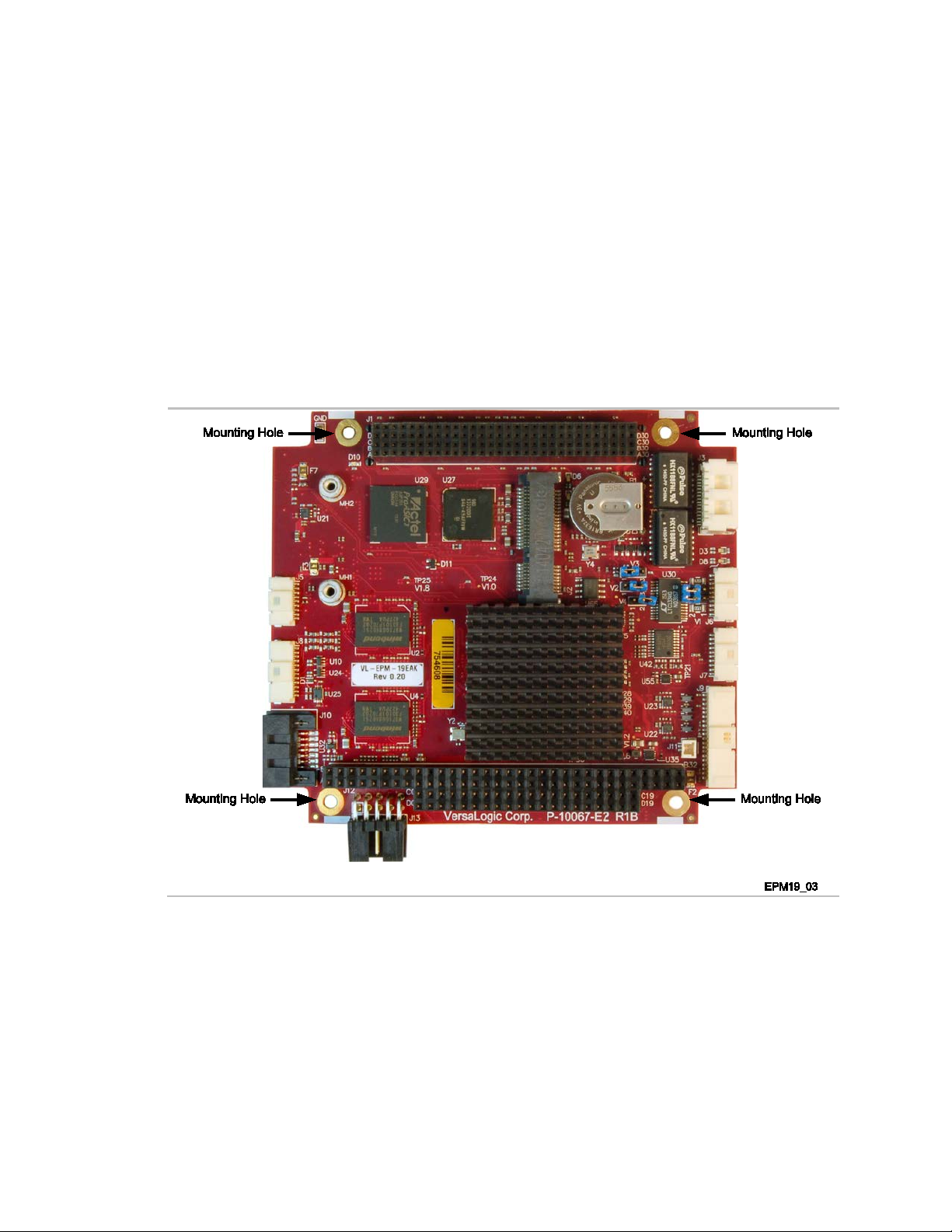
ARTH GROUND REQUIREMENT
E
All mounting standoffs should be connected to earth ground (chassis ground). This provides
proper grounding for EMI purposes. Figure 1 shows the locations of the board’s mounting holes.
All mounting holes identified in Figure 1 must be connected to earth ground.
Figure 1. Attaching the EPM-19 to Earth Ground
EPM-19 Hardware Reference Manual v
Page 6

Contents
Introduction ................................................................................................................... 1
Description .......................................................................................................................... 1
Technical Specifications ..................................................................................................... 3
EPM-19 Block Diagram ..................................................................................................... 4
Dimensions and Mounting .................................................................................................. 5
Hardware Assembly ............................................................................................... 5
Related Documents ............................................................................................................. 6
Configuration and Setup ............................................................................................... 7
Initial Configuration ........................................................................................................... 7
Basic Setup ......................................................................................................................... 7
Jumper Blocks .................................................................................................................... 9
Jumpers Blocks in the As-Shipped Configuration................................................. 9
Jumper Summary ................................................................................................. 10
BIOS Setup Program......................................................................................................... 10
CMOS/Non-volatile RAM ................................................................................... 10
Clearing CMOS RAM ......................................................................................... 11
Operating System Installation ........................................................................................... 12
ACPI Version Setting .......................................................................................... 12
Windows XP Considerations ............................................................................... 12
Linux Considerations ........................................................................................... 12
Board Features ............................................................................................................ 13
CPU ................................................................................................................................... 13
DMA Controller .................................................................................................. 13
Watchdog Timers................................................................................................. 13
Real-time Clock ................................................................................................... 13
Vortex86DX2 SoC On-chip Temperature Sensor ............................................... 14
System RAM ..................................................................................................................... 14
I/O Interfaces .................................................................................................................... 14
Power Delivery ................................................................................................................. 15
Main Power Connector ........................................................................................ 15
Cabling ................................................................................................................. 16
Battery Power Options ......................................................................................... 16
VL-CBR-0203 External Battery Module ............................................................. 17
Cabling ................................................................................................................. 18
Operating the Board without a Battery ................................................................ 19
Switches ............................................................................................................................ 20
Push-Button Reset ............................................................................................... 20
LEDs/Indicators ................................................................................................................ 20
Programmable LED ............................................................................................. 21
External Speaker ............................................................................................................... 21
Mass Storage Interfaces ............................................................................................. 22
SATA ................................................................................................................................ 22
EPM-19 Hardware Reference Manual vi
Page 7

Contents
microSD Socket ................................................................................................................ 23
Multi-purpose I/O ......................................................................................................... 25
USB ................................................................................................................................... 25
PCIe Mini Card / mSATA ................................................................................................ 25
mSATA Activity LED ......................................................................................... 27
Booting from a PCIe Minicard ............................................................................ 27
PCIe Mini Card LEDs ......................................................................................... 28
User I/O Connector ........................................................................................................... 29
Cabling ................................................................................................................. 30
Serial Ports .................................................................................................................. 31
Serial Port Connectors ...................................................................................................... 31
Serial Port Connector Pinouts ............................................................................. 32
Cabling ................................................................................................................. 32
Serial Port Assignment ..................................................................................................... 33
COM3/COM4 Hardware Configuration ........................................................................... 34
Video Interfaces ........................................................................................................... 35
Configuration ....................................................................................................... 35
VGA Interface .................................................................................................................. 36
Cabling ................................................................................................................. 37
LVDS Flat Panel Display Connector ................................................................................ 38
Cabling ................................................................................................................. 39
Compatible LVDS Panel Displays ...................................................................... 39
BIOS Settings for Boot Display Devices .......................................................................... 40
Console Redirection ......................................................................................................... 40
Enabling Synchronous Display Output ............................................................................ 41
Network Interfaces ...................................................................................................... 42
Controller Configuration ..................................................................................... 42
Ethernet Connectors ............................................................................................ 42
Cabling ................................................................................................................. 43
On-Board Ethernet Status LEDs .......................................................................... 44
Off-Board Ethernet Status LEDs ......................................................................... 44
Expansion Interfaces .................................................................................................. 45
SPX™ Expansion Bus ...................................................................................................... 45
Cabling ................................................................................................................. 46
VersaLogic SPX Expansion Modules ................................................................. 46
PC/104 Expansion Bus ..................................................................................................... 46
PC/104-Plus PCI Expansion Interface ................................................................. 47
System Resources and Maps ..................................................................................... 48
CBR-4005B Paddleboard ............................................................................................ 49
CBR-4005B Paddleboard ................................................................................................. 49
CBR-4005B Connectors and Indicators .............................................................. 49
User I/O Connector .............................................................................................. 50
Cabling ................................................................................................................. 51
Auxiliary I/O Connector ...................................................................................... 51
Dimensions and Mounting Holes ........................................................................ 52
EPM-19 Hardware Reference Manual vii
Page 8

Contents
Appendix A – References.................................................. Error! Book m ar k not defined.
Figures
Figure 1. Attaching the EPM-19 to Earth Ground ............................................................. v
Figure 2. VL- EPM-19 Fox Single Board Computer (Top Side) ....................................... 1
Figure 3. VL- EPM-19 Fox Single Board Computer (Bottom Side) ................................. 2
Figure 4. EPM-19 Block Diagram ..................................................................................... 4
Figure 5. EPM-19 Dimensions and Mounting Holes ......................................................... 5
Figure 6. Jumper Block Locations ..................................................................................... 9
Figure 7. Location of the V3 Clear CMOS Jumper ......................................................... 11
Figure 8. Location and Pin Orientation of the Main Power Connector ........................... 15
Figure 9. Location and Pin Orientation of the External Battery Connector ..................... 17
Figure 10. VL-CBR-0203 Latching Battery Module ....................................................... 17
Figure 11. Location of the V4 Battery Saver Jumper ...................................................... 18
Figure 12. Location of the V2 No Battery Mode Jumper ................................................ 19
Figure 13. Locations of the LEDs/Indicators ................................................................... 20
Figure 14. Location of the SATA Port ............................................................................. 22
Figure 15. Location of the microSD Socket..................................................................... 23
Figure 16. Location of the mSATA Activity LED ........................................................... 27
Figure 17. Location of PCIe Mini Card LEDs ................................................................. 28
Figure 18. Location and Pin Orientation of User I/O Connector ..................................... 29
Figure 19. Location and Pin Orientation of Serial Port Connectors ................................ 31
Figure 20. COM3/COM4 End-point Termination Jumpers ............................................. 34
Figure 21. VGA Connector Location and Pin Configuration .......................................... 36
Figure 22. Location of the LVDS Connector ................................................................... 38
Figure 23. Wiring for a DB9 to DB9 RS-232 Adapter for Console Redirection ............. 40
Figure 24. Location and Pin Orientation for the J3 Ethernet Connector ......................... 42
Figure 25. Location of Ethernet Status LEDs D3 and D8 ................................................ 44
Figure 26. J5 SPX Connector Location and Pin Configuration ....................................... 45
Figure 27. CBR-4005B Connectors ................................................................................. 49
Figure 28. Location and Pin Orientation of the User I/O Connector ............................... 50
Figure 29. Location and Pin Orientation of Auxiliary I/O Connector ............................. 51
Figure 30. CBR-4005B Dimensions and Mounting Holes .............................................. 52
Tables
Table 1: Technical Specifications for all EPM-19 Configurations ..................................... 3
Table 2: Jumper Summary ................................................................................................ 10
Table 3: Memory Configurations of EPM-19 Board Models ........................................... 14
Table 4: J13 Power Connector Pinout .............................................................................. 16
EPM-19 Hardware Reference Manual viii
Page 9

Contents
Table 5: Expansion Current Limits ................................................................................... 16
Table 6: Battery Saver Jumper Truth Table ...................................................................... 18
Table 7: No Battery Mode Jumper Truth Table ................................................................ 19
Table 8: PCIe Mini Card / mSATA Pinout ....................................................................... 25
Table 9: Primary Boot Device Truth Table ....................................................................... 27
Table 10: PCIe Mini Card LED States .............................................................................. 28
Table 11: J9 I/O Connector Pinout and Pin Orientation ................................................... 30
Table 12: J7 COM1/COM2 Connector Pinout ................................................................. 32
Table 13: J6 COM3/COM4 Connector Pinout ................................................................. 32
Table 14: Recommended Serial Port Settings for Vortex86DX2 BIOS ........................... 33
Table 15: COM3/COM4 Termination Jumpers ................................................................ 34
Table 16: J8 VGA Video Output Pinout ........................................................................... 37
Table 17: J15 LVDS Flat Panel Display Connector Pinout .............................................. 39
Table 18: Compatible LVDS Interface TFT-Technology Flat Panel Displays ................. 39
Table 19: BIOS Settings for Boot Display Devices and Corresponding Resolutions ...... 40
Table 20: Ethernet Connector Pinout ................................................................................ 43
Table 21: On-board Ethernet Status LEDs (D3 and D8) ................................................. 44
Table 22: SPX Connector Pinout ...................................................................................... 46
Table 23: PC/104 ISA I/O, IRQ, and Memory Resources ................................................ 47
Table 24: User I/O Connector Pinout ............................................................................... 50
Table 25: Auxiliary I/O Connector Pinout ........................................................................ 51
EPM-19 Hardware Reference Manual ix
Page 10
1
Description
The EPM-19 is a feature-packed single board computer designed for OEM control projects
requiring fast processing, with two memory density options and designed-in reliability and
longevity (product lifespan).
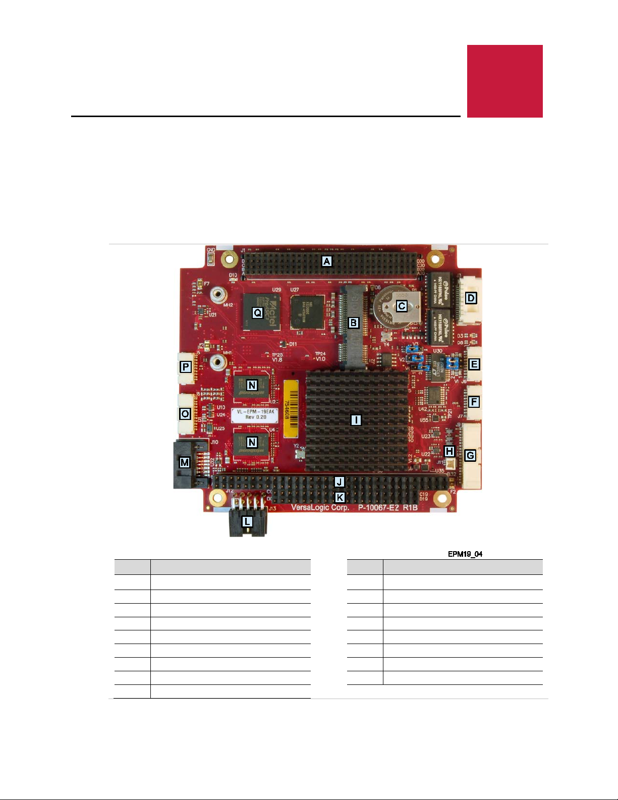
Figure 2 shows the connectors and major components on the top side of the board. Figure 3
shows the connectors and major components on the bottom side of the board.
Introduction
EPM-19 Hardware Reference Manual 1
Item Description
A
PC/104-Plus (PCI) connector
B PCIe Minicard/mSATA connector K PC/104 (ISA) connector
C Battery L Main power connector
D Ethernet port 0/1 connector M SATA connector
E COM3/COM4 connector N DRAM devices
F COM1/COM2 connector O VGA connector
G User I/O [CBR-4005B mating connector] P SPX connector
H External battery connector Q FPGA device
I Vortex86DX2 SoC
Figure 2. VL- EPM-19 Fox Single Board Computer (Top Side)
Item Description
J PC/104 (ISA) connector
Page 11
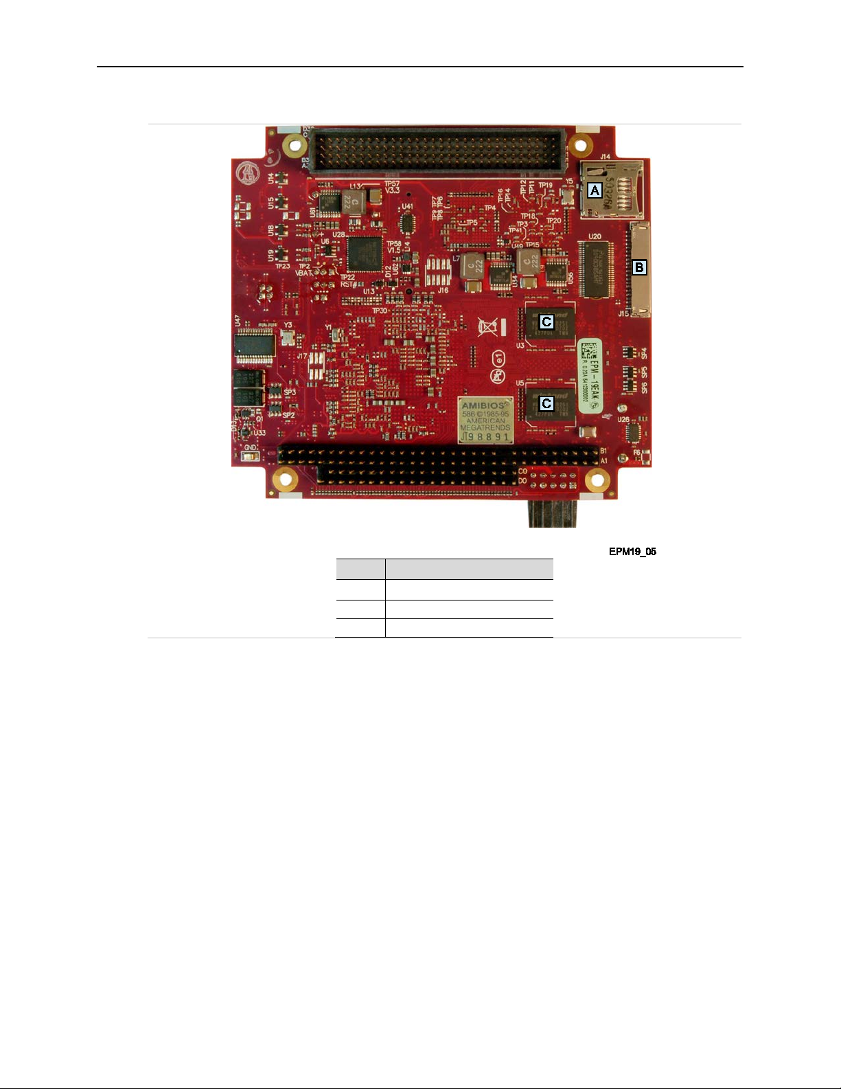
Introduction
Item Description
A microSD socket
B LVDS connector
C DRAM devices
Figure 3. VL- EPM-19 Fox Single Board Computer (Bottom Side)
EPM-19 boards are subjected to 100% functional testing and are backed by a limited five-year
warranty. Careful parts sourcing and US-based technical support ensure the highest possible
quality, reliability, service and product longevity for this exceptional SBC.
EPM-19 Hardware Reference Manual 2
Page 12

Technical Specifications
temperature (Note)
• Video BIOS supports up t o 1024x768 resolut i on with 32-bi t color
limited to 1024x768 (LVDS panel maximum supported resolution)
Video BIOS support for 640x480, 800x480, 800x600, 1024x600, and 1024x768
Vcc sensing; resets when the 5V, 3.3V, 1.8V, 1.5V, 1. 2V , or 1.0V power rails vary by more than
± 10% of their optimal val ues .
Supports SPI and SPX devices. Supports up to two SPX modules, including low cost analog
signals)
bus speed
SPX™ – full compliance
Generated
100 MHz, 50 MHz, 33 MHz, 29.49 MHz, 25 MHz, 14.318 MHz, 8 MHz, 4 MHz, 2 MHz, 1 MHz,
Specifications are typical at 25 °C with 5.0V supply, unless otherwise noted. Specifications are
subject to change without notice.
Table 1: Technical Specifications for all EPM-19 Configurations
Item VL-EPM-19SAK VL-EPM-19SBK VL-EPM-19EAK VL-EPM-19EBK
(Standard Temperature) (Extended Temperature)
Board size 4.250 inches x 3.775 inches
Storage temperature -40 °C to 85 °C
Free air operating
CPU clock 933 MHz 800 MHz
Memory clock 333 MHz 300 MHz
Memory size 512 MB 1 GB 512 MB 1 GB
Idle power 5.3 W 5.3W 5.0 W 5.0 W
Typical power 5.5 W 5.6 W 5.3 W 5.4 W
Max power 5.8 W 5.9 W 5.7 W 5.8 W
Input Voltage +5 VDC ±5%
Introduction
0 °C to + 60 °C -40°C to +85 °C
Analog VGA output
Digital Video output
System Reset
Ethernet interface Two auto-detect 10BaseT/100BaseT X ports
COM1-2 interface RS-232, 16C550 compatible, 115k baud max.
COM3-4 interface RS-232/422/485, 16C550 compati bl e, 460k baud max.
SPI interface
GPIO/Timers
BIOS AMI Vortex86DX2 BIOS
PC/104-Plus (PCI)
bus speed
PC/104 (ISA)
Compatibility
Weight 0.50 lb (0.22 kg)
frequencies
Notes: Derate -1.1°C per 305m (1,000 ft .) above 2,300m (7,500 ft.).
• With VGA driver support s up to 1920x1440. Synchronous display use causes VGA to be
• LVDS video output
• Support for 18-bit or 24-bit single c hannel LV DS flat panel displays
•
and digital modules.
Three 8254-compatible timer/counters (FPGA functions, six muxed with the eight GPIO
33 MHz
8 MHz
• PC/104 – full compl i ance
• Embedded-PCI (PC/104-Plus) – full compli ance, 3.3V signaling
•
32.768 kHz
EPM-19 Hardware Reference Manual 3
Page 13
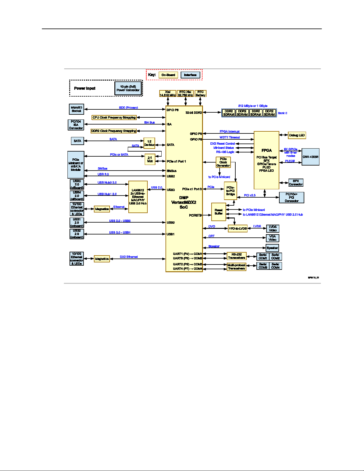
EPM-19 Block Diagram
Introduction
Figure 4. EPM-19 Block Diagram
EPM-19 Hardware Reference Manual 4
Page 14
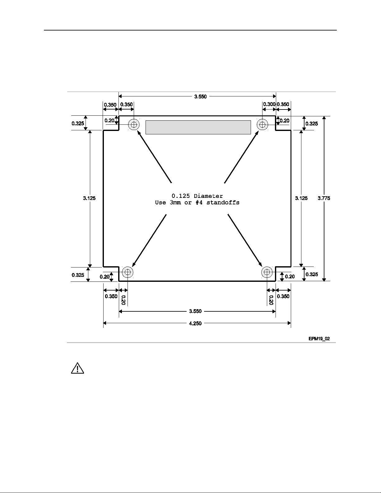
Dimensions and Mounting
The EPM-19 must be supported at all four mounting points to prevent
not covered under the product warranty.
The EPM-19 complies with the PC/104 standard which provides for specific mounting hole and
PC/104-Plus stack locations as shown in Figure 5.
Introduction
Figure 5. EPM-19 Dimensions and Mounting Holes
(Not to scale. All dimensions in inches.)
CAUTION:
excessive flexing when expansion modules are attached and removed. Flex
damage caused by excessive force on an improperly mounted circuit board is
HARDWARE ASSEMBLY
The EPM-19 mounts on four hardware standoffs using the corner mounting holes. These
standoffs are secured to the underside of the circuit board using pan head screws.
EPM-19 Hardware Reference Manual 5
Page 15

The entire assembly can sit on a table top or be secured to a base plate. When bolting the unit
http://www.vortex86.com/?p=16
USB 2.0 Hub and 10/100
down, make sure to secure all standoffs to the mounting surface to prevent circuit board flexing.
An extractor tool is available (part number VL-HDW-201) to separate the PC/104 modules from
the stack.
Related Documents
The following documents available are on the EPM-19 Product Support Web Page:
EPM-19 Programmer’s Reference Manual – provides information on the board’s resources
(memory, I/O, and IRQs), a description of the FPGA’s registers, and programming
information for the board’s hardware interfaces.
EPM-19_EBX-18 BIOS Reference Manual – provides information on accessing and
configuring settings in the BIOS Setup utility. All BIOS menus, submenus, and
configuration options are described.
VersaAPI Installation and Reference Guide – describes the shared library of API calls for
reading and controlling on-board devices on certain VersaLogic products.
Additional documents:
Introduction
Overview of Vortex86DX2
Ethernet Controller
ILAN9512 Data sheet
PC/104 Specification
PC/104-Plus Specification
http://ww1.microchip.com/downloads/en/DeviceDoc/9512.pdf
http://www.versalogic.com/products/PC104/index.asp
http://www.versalogic.com/products/PC104/index.asp
EPM-19 Hardware Reference Manual 6
Page 16

2
Initial Configuration
The following components are recommended for a typical development system.
EPM-19 single board computer
ATX power supply with motherboard and disk drive connectors
VGA video monitor
USB Keyboard
USB Mouse
SATA hard drive
The following VersaLogic cables and accessories are recommended.
VGA Video adapter cable (CBR-1204)
Configuration and Setup
User I/O cable (CBR-4005) and accompanying paddleboard (CBR-4005B)
Power adapter cable (CBR-1008)
VL-CBR-0702 – SATA data cable
VL-CBR-0401 – ATX to SATA power adapter
You will also need a Windows (or other OS) installation CD/DVD and corresponding drive.
Basic Setup
The following steps outline the procedure for setting up a typical development system. The
EPM-19 should be handled at an ESD workstation or while wearing a grounded antistatic wrist
strap.
Before you begin, unpack the EPM
you ordered. Inspect the system visually for any damage that may have occurred in shipping.
Contact support@versalogic.com
Gather all the peripheral devices you plan to attach to the EPM-19 and their interface and power
cables.
It is recommended that you attach standoffs to the board now to stabilize the board and make it
easier to work with. (Refer to the section titled “Hardware Assembly” on page 5.)
1. Connect Power
-19 and accessories. Verify that you received all the items
immediately if any items are damaged or missing.
EPM-19 Hardware Reference Manual 7
Plug the power adapter cable CBR-1008 into connector J13. Attach the motherboard
connector of the ATX power supply to the adapter.
To use the Lithium Battery with the EPM
to connecting pin 1 and pin 2. Refer to the section titled “
for more information.
-19, move the jumper on V4 from being stored on pin 1
Battery Saver Jumper” on page 18
Page 17

Configuration and Setup
If you intend to operate the EPM-19 under Windows XP or Windows XP Embedded, be sure to
use Service Pack 3 (SP3).
2. Attach Cables and Peripherals
Plug the video adapter cable CBR-1204 into connector J8. Attach the video monitor (VGA
DB15) interface cable to the video adapter.
Connect the CBR-4005B paddleboard to the EPM-19 using a CBR-4005 cable
Plug USB keyboard and mouse into any of the available USB ports on the CBR-4005B
paddleboard.
Plug a USB DVD-ROM drive into any of the available USB ports on the CBR-4005B
paddleboard. To avoid potential device delays and excessive power consumption through
the USB ports, use an external power supply for the USB CD-ROM drive.
Plug the SATA data cable VL-CBR-0702 into the SATA connector (J10). Attach a SATA
hard drive to the other end of the cable.
Attach the SATA power adapter cable VL-CBR-0401 to the ATX power supply and SATA
drive.
3. Review Configuration
Before you power up the system, double check all the connections. Make sure all cables are
oriented correctly and that adequate power will be supplied to the EPM
-19 and peripheral
devices.
4. Power On
Turn on the ATX power supply and the video monitor. If the system is correctly configured,
a video signal should soon be present.
5. Change BIOS Setup utility settings
Enter the BIOS Setup utility by pressing <Delete> during the early boot cycle.
Verify that the desired primary boot device is listed as such. Refer to Table 9 on page 27 for
more information.
Before saving the BIOS Setup utility settings, insert the Windows (or other OS) installation
disk in the DVD-ROM drive so it will be accessed when the system reboots.
Press <F10> and write the new parameters to CMOS RAM. The system will reboot.
6. Install an Operating System
Install the operating system according to the instructions provided by the operating system
manufacturer. (See Operating System Installation.)
Note:
EPM-19 Hardware Reference Manual 8
Page 18

Jumper Blocks
JUMPERS BLOCKS IN THE AS-SHIPPED CONFIGURATION
Configuration and Setup
Figure 6. Jumper Block Locations
EPM-19 Hardware Reference Manual 9
Page 19

JUMPER SUMMARY
Out – COM3 End-point termination disabled (default)
• Out – COM4 End point termination disabled (default)
• 2-3 – Clear CMOS RAM
• 2-3 – Battery is installed (default)
• 1-2 – Battery is connected
Configuration and Setup
Table 2: Jumper Summary
Jumper
Block
COM3 Rx End-point termination
V1 [1-2]
V1 [3-4]
V3
V2
V4
• In – COM3 End-point termination enabled
•
COM4 Rx End-point termination
• In – COM4 End-point termination enabled
CMOS RAM Clear
• 1-2 – Normal mode (default)
No Battery Mode
• 1-2 – Battery has been removed
Battery Saver
• 1 only (or jumper is removed) (default)
BIOS Setup Utility
The EPM-19 permits users to modify the BIOS Setup utility defaults. Refer to the
EPM-19_EBX-18 BIOS Reference Manual (available on the EPM-19 Product Support Web Page
for information on accessing and configuring settings in the BIOS Setup utility. All BIOS
menus, submenus, and configuration options are described in the EPM-19_EBX-18 BIOS
Reference Manual.
Description Reference
Table 15, page 34
Table 15, page 34
Clearing CMOS RAM,
page 11
Operating the Board
without a Battery, page 19
Battery Saver Jumper,
page 18
)
CMOS/NON-VOLATILE RAM
The Vortex86DX2 SoC contains a small amount of CMOS/Non-volatile RAM to store the BIOS
Setup utitlity settings. If you have modified BIOS Setup utility settings and the board fails to
boot, clear the CMOS/Non-volatile RAM to restore the default BIOS settings.
EPM-19 Hardware Reference Manual 10
Page 20

Configuration and Setup
Integrator’s Note:
If clearing the contents of CMOS RAM fails to restore the board to proper operation and you are
unable to enter the BIOS Setup utility, the EPM-19 needs to be serviced by the factory.
CLEARING CMOS RAM
To clear the contents of CMOS RAM and the Real-Time Clock:
1. Power off the EPM-19.
2. Remove the V3 jumper from its default position (connecting pins 1-2) and install it on pins
2-3. Figure 7 shows the location of the V3 jumper block.
3. Leave the jumper in place for at least five seconds.
4. Move the jumper to back to its default position, connecting pins 1-2.
5. Power on the EPM-19.
Figure 7. Location of the V3 Clear CMOS Jumper
EPM-19 Hardware Reference Manual 11
Page 21

Operating System Installation
Integrator’s Note:
The EPM-19 board supports only the 32-bit versions of Windows 7 and Windows Embedded
Standard 7 (WES7).
An operating system installed on a different type of computer is not guaranteed to work on the
each system. This restriction does not apply if you are producing multiple identical systems.
Integrator’s Note:
The EPM-19 board has been tested extensively with Windows 7 and seems to operate reliably
required by the OS.
The standard PC architecture used on the EPM-19 makes the installation and use of most of the
standard x86 processor-based operating systems relatively simple. The operating systems listed
on the VersaLogic OS Compatibility Chart
the maker of the OS. Special optimized hardware drivers for a particular operating system, or a
link to the drivers, are available at the
Note:
EPM-19. This is referred to as a “foreign” installation. A hard disk that was used to boot a
different computer cannot necessarily be moved to the EPM-19 and expected to boot. Even
when porting an OS image from one revision of the EPM-19 to another, performance might fail
or be impaired. For the best results, perform a fresh installation of the operating system on
EPM-19 Product Support Web Page.
Configuration and Setup
use the standard installation procedures provided by
ACPI VERSION SETTING
The ACPI version will need to be configured in the BIOS Setup utility as follows:
For Windows 7, set the ACPI version to V3.0. (Windows 7 requires version 2.0 or later.)
For Windows XP, set the ACPI version to V1.0 (Windows XP may function with version 2.0
but has not been fully tested.)
with the ACPI version set to V3.0. Other operating systems may have unique requirements for
setting the supported ACPI version. ACPI can be disabled in the BIOS Setup utility if it is not
WINDOWS XP CONSIDERATIONS
When Windows XP is loaded on an mSATA card, it may be necessary to change the IDE
Operate Mode setting in the BIOS Setup utility from Legacy Mode to Native Mode for the
operating system to boot properly.
INUX CONSIDERATIONS
L
If the microSD card is installed prior to board power-up, the board will expect to boot from the
microSD card because it appears as the Primary IDE device. If that is not the desired
configuration (that is, you want to boot from SATA or mSATA and use the microSD card as
storage device), you can fix this by modifying the GRUB root= boot argument from sdaX to
sdbX while the SD card is inserted. If Knoppix is installed to the SATA using Flash Install
utility instead of HD install, it won't use GRUB. Knoppix uses isolinux and is able to detect the
drive upon which Knoppix is installed.
EPM-19 Hardware Reference Manual 12
Page 22

CPU
DDR2 memory controller
10/100 Ethernet MAC Controller
3
Board Features
The DMP Electronics Vortex86DX2 System-On-a-Chip (SoC) contains a 32-bit x86 (486DX
enhanced) microprocessor that also integrates the following:
Embedded 2 MB BIOS flash memory
PCIe bus running at 2.5 GHz
ISA bus interface
Real Time Clock
Peripheral controllers with DMA and
interrupt timer/counter
DMA
CONTROLLER
The DMA circuitry incorporates the functionality of two 82C37 DMA controllers with seven
independently programmable channels. The Master DMA Controller (DMA-1) corresponds to
DMA Channels 0-3 that are hardwired to 8-bit count-by-byte transfers and the Slave DMA
Controller (DMA-2) corresponds to Channels 5-7 that are hardwired to 16-bit count-by-word
“address shifted” transfers. DMA Channel 4 is used to cascade the two controllers and will
default to cascade mode as it cannot be used for any other purpose. In addition to accepting
requests from DMA slaves, the DMA controller also responds to requests that are initiated by
software.
The Vortex86DX2 provides the timing control and data size translation for the DMA transfer
between memory (ISA or DRAM) and the ISA bus I/O. Also, the DX2 is ISA-compatible with
24-bit addressing. For information on programming the DMA controller, contact
Support@VersaLogic.com
.
GPU
COM ports (FIFO UART)
USB 2.0 host controller
IDE controller (SD and SATA)
Watchdog timers
WATCHDOG TIMERS
The watchdog timers use the RTC frequency (32.768 kHz) for a 24-bit counter, providing a time
range from 30.5 μs to 512 seconds with a resolution of 30.5 μs. When the timer is enabled and
its count reaches the programmed value, a system reset, NMI, or IRQ may occur as selected
using the Watchdog Configuration sub-menu in the BIOS Setup utility.
EAL-TIME CLOCK
R
The EPM-19 features a battery-backed real-time clock/calendar. Under normal battery use
EPM-19 Hardware Reference Manual 13
conditions, the clock maintains accurate timekeeping functions when the board is powered off.
The BIOS Setup utility can be used to set the time/date of the real-time clock.
Page 23

VORTEX86DX2 SOC ON-CHIP TEMPERATURE SENSOR
Contact the factory for information on reading and writing to the thermometer circuits.
System RAM
The EPM-19 is equipped with 512 MB or 1 GB of 1.8 V DDR2 memory soldered to the board.
EPM-19SAK — Standard temperature 512 MB 333 MHz
EPM-19SBK — Standard temperature 1 GB 333 MHz
EPM-19EAK — Extended temperature 512 MB 300 MHz
EPM-19EBK — Extended temperature 1 GB 300 MHz
I/O Interfaces
The EPM-19 board’s I/O interfaces and their associated connectors are described in later
chapters as follows:
Board Features
Table 3: Memory Configurations of EPM-19 Board Models
Board Model Installed Memory Size M emory Clock
Mass Storage Interfaces (SATA and microSD), beginning on page 22
Multi-purpose I/O (USB, PCIe MiniCard / mSATA, User I/O), beginning on page 25
Serial Ports, beginning on page 31
Video Interfaces (VGA, LVDS), beginning on page 35
Network Interfaces (Ethernet), beginning on page 42
Expansion Interfaces (SPX, PC/104), beginning on page 45
EPM-19 Hardware Reference Manual 14
Page 24

Power Delivery
The +3.3 VDC, +12 VDC and -12 VDC inputs on the power connector are only required for
PC/104-Plus and PC/104 expansion modules that require these voltages.
MAIN POWER CONNECTOR
Figure 8 shows the location and pin orientation of the main power connector.
Board Features
Figure 8. Location and Pin Orientation of the Main Power Connector
CAUTION:
To prevent severe and possibly irreparable damage to the system, it is c r it ical
that the power connector is wired correctly. Make use of all +5 VDC pins and
all ground pins to prevent excess voltage drop.
Note:
EPM-19 Hardware Reference Manual 15
Page 25

Table 4 lists the pinout for power connector.
1
Ground
2
+5 VDC
3
Ground
4
+12 VDC
5
Ground
6
-12 VDC
7
+3.3 VDC
8
+5 VDC
9
Ground
10
+5 VDC
+3.3 V
3 A
+5 V
4 A
+12 V
1 A
-12 V
0.5 A
To prevent shorting, premat ure failure or damage to the Lithium bat tery, do not
the battery in fire. Dispose of used batteries promptly.
Table 4: J13 Power Connector Pinout
Board Features
Pin Signal
Pin Signal
Table 5 lists the maximum current available for expansion for the power supply voltages.
Table 5: Expansion Current Limits
Voltage Maximum Expansion Current
CABLING
An adapter cable, part number CBR-1008, is available for connecting the EPM-19 to an ATX
power supply.
If your application requires a custom cable, the following information will be useful:
EPM-19 Board Connector Mating Connector
FCI 78207-110HLF FCI 69176-010LF
BATTERY POWER OPTIONS
The battery circuit on the EPM-19 provides power for the Real-Time Clock (RTC) and power to
store BIOS Setup utility settings in CMOS RAM.
CAUTION:
place the board on a conductive surface such as metal, black conductive foam
or the outside surface of a m etalized ESD protective pouch. The Lithium
battery may explode if mistreated. Do not rechar ge, disassemble, or dispose of
Nominal battery voltage is 3.0V. If the voltage drops below 2.7V, contact the factory for a
replacement. The life expectancy under normal use is approximately five years.
EPM-19 Hardware Reference Manual 16
Page 26

Board Features
The EPM-19 has multiple options for providing battery power:
Use the on-board battery
Use the battery supplied with the CBR-4005B paddleboard
Use an external battery, connected to the board through the J11 external battery connector.
Figure 9 shows the location and pin orientation of the external battery connector.
Figure 9. Location and Pin Orientation of the External Battery Connector
VL-CBR-0203 EXTERNAL BATTERY MODULE
The VL-CBR-0203 external battery module is compatible with the EPM-19. For more
information, contact
EPM-19 Hardware Reference Manual 17
Sales@VersaLogic.com.
Figure 10. VL-CBR-0203 Latching Battery Module
Page 27

Board Features
Battery is disconnected
(not discharging)
CABLING
If your application requires a custom cable, the following information will be useful:
EPM-19 Board Connector Mating Connector
Molex 501331-0207 Molex 501330-0200
Battery Saver Jumper
The EPM-19 includes a “Battery Saver” jumper at location V4. This jumper keeps the Lithium
battery from discharging (keeping it disconnected) before the EPM-19 board is in the customer’s
hands and ready to be used. The default configuration of the jumper is a no-connect position
(placed only on pin 1). Figure 11 shows the location of the V4 Battery Saver Jumper.
Table 6: Battery Saver Jumper Truth Table
V4 Jumper Position Condition
Pin 1 only (default)
Pin 1-2 Battery is connected
EPM-19 Hardware Reference Manual 18
Figure 11. Location of the V4 Battery Saver Jumper
Page 28

Board Features
OPERATING THE BOARD WITHOUT A BATTERY
The EPM-19 enables you to operate the board without a battery for applications when no battery
is required. Using this setting will delay the board’s booting process after power on for
approximately 5 seconds. This is an application requirement to give the RTC crystal time to start
up.
Table 7: No Battery Mode Jumper Truth Table
V2 Jumper Position Condition
Pin 2-3 (default) Battery is inst al l ed or will be used
Pin 1-2 Battery is not present and not in use
Figure 12. Location of the V2 No Battery Mode Jumper
To operate the board without the Lithium battery, perform the following steps:
1. Power down the EPM-19.
2. Remove the battery connection to the SoC RTC well. This is done by removing the V4
jumper leaving pins 1 and 2 unconnected if you want to keep the battery with the product
(otherwise the on-board battery would have to be unsoldered). You can store the V4
jumper in its default position connected only to pin 1.
3. Make certain there are no other batteries connected to the board; that is, either attached
to the J11 external battery connector or on the CBR-4005B paddleboard. If you are
using the CBR-4005B paddleboard, remove the battery from its socket.
4. Set the V2 jumper to pins 1-2. (Always make sure the battery is disconnected when this
jumper setting is used or it will drain the battery and delay booting of the board.)
5. Power up the EPM-19. The board takes approximately five seconds to begin the boot
sequence after the power switch is turned on when the battery is not in use. This delay is
necessary for the RTC crystal operation to stabilize before the board reset is released.
EPM-19 Hardware Reference Manual 19
Page 29

Switches
PUSH-BUTTON RESET
User I/O connector J9 includes an input for a push-button reset switch. Shorting J9, pin 18 to
ground causes the EPM-19 to reboot.
A reset button is provided on the CBR-4005B paddleboard. See Figure 27 on page 49 for the
location of the reset button on the CBR-4005B paddleboard.
LEDs/Indicators
Figure 13 shows the locations of the boards LEDs/indicators.
Board Features
LED(s) Description For more information, see…
D10 mSATA activity LED Page 27
D6/D5 PCI Mini Card LEDs Page 28
D3/D8 Ethernet s tatus LEDs Page 44
Figure 13. Locations of the LEDs/Indicators
EPM-19 Hardware Reference Manual 20
Page 30

PROGRAMMABLE LED
User I/O connector J9 includes an output signal for attaching a software controlled LED.
Connect the cathode of the LED to J9, pin 16; connect the anode to +5V. An on-board resistor
limits the current to 15 mA when the circuit is turned on. A programmable LED is provided on
the CBR-4005B paddleboard. See Figure 27 on page 49 for the location of the Programmable
LED on the CBR-4005B paddleboard.
For instructions on how to switch the Programmable LED on and off, refer to the EPM-19
Programmer’s Reference Manual (available on the EPM-19 Product Support Web Page
External Speaker
A miniature 8 Ω speaker can be connected between user I/O connector J9, pin 15 (SPKR#) and
J9, pin 13 (V3P3). A speaker is provided on the CBR-4005B paddleboard. See Figure 27 on
page 49 for the location of the speaker on the CBR-4005B paddleboard.
Board Features
).
EPM-19 Hardware Reference Manual 21
Page 31

Integrator’s Note:
Only one SATA port is available on the Vortex86DX2 chip, so only the J10 SATA port or the J2
card installed, the mSATA card uses the single SATA port.
4
SATA
The EPM-19 provides a 1.5 Gbit/s SATA port. Power to the SATA drive is usually provided by
the ATX power supply. Note that the standard SATA drive power connector is different from
the typical 4-pin Molex connector used on IDE drives. Most current ATX power supplies
provide SATA connectors, and many SATA drives provide both types of power connectors. If
the power supply you are using does not provide SATA connectors, adapters are available.
Mass Storage Interfaces
mSATA port can be used; both cannot be used at the same time. Whenever J2 has an mSATA
Figure 14. Location of the SATA Port
EPM-19 Hardware Reference Manual 22
Page 32

microSD Socket
The EPM-19 includes a microSD socket on the underside of the board. The VL-F41 series of
microSD cards provide solid-state storage of 2 GB, 4 GB, or 8 GB. The microSD socket
accommodates cards with up to 32 GB of storage capacity. No drivers are needed, as the device
interface is abstracted as a standard parallel IDE drive on the master IDE channel.
Mass Storage Interfaces
Figure 15. Location of the microSD Socket
Note the following when using a microSD card with the EPM-19:
The microSD card interface is not hot-pluggable. A microSD card will not be recognized as
part of the system if it is not plugged in before power is applied to the board or before a
push-button reset is applied. This is not a limitation of the EPM
-19 board; it is a limitation of
the DX2 chip.
When a microSD card is inserted at power-up, the default boot setting is to boot from it (it is
primary), so if you don’t press <F11> right after applying power to the board, you will not be
able to select an alternate boot option; the board will “stall” for the lack of an operating
system (OS) if there isn’t one present on the microSD card.
The boot order can be changed in the BIOS Setup utility.
EPM-19 Hardware Reference Manual 23
Page 33

Mass Storage Interfaces
If you remove the microSD card at any time and allow the board to boot without the card
installed, the boot order setting will be cleared and you will have to set it up again the next
time you use a microSD card.
If you remove the microSD card while the board is powered on and the OS attempts to access
a file on the “drive” (that is, the microSD card) the results are unpredictable. The best case
scenario is that the drive drops out (as it would in Windows Explorer when running
Windows 7 from a SATA drive and using the microSD as an additional hard drive).
However, if Windows does not try to access the microSD card while you have it out and you
put it back in (again, in Windows 7 at least) the system does not appear to have noticed it
was ever removed.
EPM-19 Hardware Reference Manual 24
Page 34

USB
Note:
as non-bootable FAT32 drives.
Note:
PCIe Mini Cards using small (512 byte or below) I/O address ranges may not be accessible.
Pin
Signal Name
Function
Signal Name
Function
1 WAKE#
Wake Reserved
Not connected
2 3.3VAUX
3.3V auxiliary source
+3.3V
3.3V source
3 NC
Not connected
Reserved
Not connected
4 GND
Ground GND
Ground
5 NC
Not connected
Reserved
Not connected
6 1.5V
1.5V power
+1.5V
1.5V power
7 NC
Not connected
Reserved
Not connected
5
Multi-purpose I/O
The USB interface on the EPM-19 is OHCI (Open Host Controller Interface) and EHCI
(Enhanced Host Controller Interface) compatible, which provides a common industry
software/hardware interface. The USB controller can be enabled or disabled in the BIOS Setup
utility. The board has four USB ports:
Two hub ports routed to the J9 user I/O connector. Table 11 page 30 lists the USB port
signals routed to the J9 user I/O connector.
Two additional non-hub ports are also routed to the J9 user I/O connector.
Some USB mass storage devices cause long delays or reboot cycles when formatted
The USB interfaces at connector J9 are accessible using a CBR-4005B paddleboard or by using a
custom cable.
All four USB ports use IEC 61000-4-2-rated TVS components to protect against ESD damage.
PCIe Mini Card / mSATA
The socket at location J2 accepts a full-height PCI Express Mini Card or an mSATA module.
The PCIe Mini Card interface includes one PCIe x1 lane, one hubbed USB 2.0 channel, and the
SMBus interface. The socket is compatible with plug-in Wi-Fi modems, GPS receivers, Flash
data storage, and other cards for added flexibility. For more information on PCIe Mini Cards
offered by VersaLogic, contact
To secure a Mini Card or mSATA module to the on-board standoffs, use two M2.5 x 6mm pan
head Philips nylon screws. These screws are available in quantities of 10 in the VL-HDW-108
hardware kit from VersaLogic.
J2
PCIe Mini Card
Sales@VersaLogic.com.
Table 8: PCIe Mini Card / mSATA Pinout
PCIe Mini Card
mSATA
mSATA
8 NC Not connected Reserved Not connected
9 GND Ground GND Ground
EPM-19 Hardware Reference Manual 25
Page 35

Multi-purpose I/O
Pin
Signal Name
Function
Signal Name
Function
10 NC
Not connected
Reserved
Not connected
11 REFCLK-
Reference clock input –
Reserved
Not connected
12 NC
Not connected
Reserved
Not connected
13 REFCLK+
Reference clock input +
Reserved
Not connected
14 NC
Not connected
Reserved
Not connected
17 NC
Not connected
Reserved
Not connected
18 GND
Ground GND
Ground
19 NC
Not connected
Reserved
Not connected
20 W_DISABLE#
Wireless di sable
Reserved
Not connected
21 GND
Ground GND
Ground
22 PERST#
Card reset
Reserved
Not connected
23 PERn0
PCIe receive –
+B
Host receiver diff. pair +
25 PERp0
PCIe receive +
-B
Host receiver diff. pair –
26 GND
Ground GND
Ground
27 GND
Ground GND
Ground
28 1.5V
1.5V power
+1.5V
1.5V power
29 GND
Ground GND
Ground
30 SMB_CLK
SMBus clock
Two Wire I/F
Two wire I/F clock
31 PETn0
PCIe transmit –
-A
Host transmitt er di ff. pair –
33 PETp0
PCIe transmit +
+A
Host transmitter di ff. pair +
34 GND
Ground GND
Ground
35 GND
Ground GND
Ground
36 USB_D-
USB data –
Reserved
Not connected
37 GND
Ground GND
Ground
38 USB_D+
USB data +
Reserved
Not connected
39 3.3VAUX
3.3V auxiliary source
+3.3V
3.3V source
42 LED_WWAN#
Wireless WAN LED
Reserved
Not connected
Note 1
Note 1
45 NC
Not connected
Vendor
Not connected
46 LED_WPAN#
Wireless P AN LED
Reserved
Not connected
47 NC
Not connected
Vendor
Not connected
48 1.5V
1.5V power
+1.5V
1.5V power
49 Reserved
Reserved DA/DSS
Device activity (Note 2)
50 GND
Ground GND
Ground
51 Reserved
Reserved GND
Ground (Note 3)
52 3.3VAUX
3.3V auxiliary source
+3.3V
3.3V source
Notes:
1. This pin is not grounded on the EPM-19 since it can be used to detec t the presence of an mSAT A module
pull-down enabled in the EPM-19 FPGA to keep the SATA channel mux from switc hi ng when J2 i s empty.
2. This signal drives the blue LE D activity indicator at loc ation D10 in the lower right corner of the board (refer to
3. Some PCIe modules use this signal as a s econd Mini Card wireless disable input. On t he E PM-19, this signal is
used as the default indicator for mSATA versus PCIe Mini Card detection.
J2
15 GND Ground GND Ground
16 NC Not connected Reserved Not connected
24 3.3VAUX 3.3V auxiliary source +3.3V 3.3V source
32 SMB_DATA SMBus data Two Wire I/F Two wire I/F data
PCIe Mini Card
PCIe Mini Card
mSATA
mSATA
40 GND Ground GND Ground
41 3.3VAUX 3.3V auxiliary source +3.3V 3.3V source
43
44 LED_WLAN# Wireless LAN LED Reserved Not connected
versus a PCIe Mini Card. Grounding this pi n i s available as an option on custom boards, but this pin already has a
Figure 16). This LED lights with mSATA disk ac t i vi t y, i f supported by the mSATA module.
GND
mSATA detect (
)
GND/NC
EPM-19 Hardware Reference Manual 26
Ground/not connected (
)
Page 36

Multi-purpose I/O
Note:
attached, the BIOS Setup utility will not recognize any device attached to the SATA connector.
SATA ACTIVITY LED
M
Figure 16 shows the location of the mSATA activity LED. This LED indicates activity on the
mSATA interface. Not all mSATA drives provide this disk activity signal. Note that the FPGA
register bit for the DEBUG_LED needs to be cleared (set to 0) in order for this signal to reflect
the MSATA_DAS signal from the mSATA interface. Until that is done, it reflects the status of
the FPGA programming (set to 1 when the FPGA is programmed and reset properly). Refer to
the EPM-19 Programmer’s Reference Manual (available on the
EPM-19 Product Support Web
Page) for information on FPGA registers.
Figure 16. Location of the mSATA Activity LED
BOOTING FROM A PCIE MINICARD
The MSATA_DETECT (J2 pin 43) signal is non-functional as an option for the PCIe Minicard
mux selection. This signal has a pull-down internal to the FPGA to prevent it from floating high
(which enables it). The FPGA default is to use J2 pin 51 as the mux enable signal
(PRES_DISABLE2#) which works with all of our Minicards.
The result of this condition is that certain combinations of bootable devices may not yield
expected results. Table 9 is a matrix of acceptable boot device configurations.
Table 9: Primary Boot Device Truth Table
Installed Bootable Devices
microSD card mSATA c ar d External SATA Drive USB Flash Drive
Yes Don’t c are Don’t care Don’t care microSD card
No Yes Don’t care Don’t care mSATA card
No No Yes Don’t care External SATA drive
No No No Yes USB Flash Drive
The primary boot
device will be…
Only one SATA port is available on the Vortex86DX2 SoC. If an mSATA device is
EPM-19 Hardware Reference Manual 27
Page 37

Multi-purpose I/O
Illuminates when the 3.3 V power to the Mini Card is on. It alerts users to not hot-
powered successfully.
Note: These LEDs will illuminate when the associated device is installed and capabl e of transmitting. Thei r function is
determined by the installed device.
PCIE MINI CARD LEDS
Two dual-colored PCIe Mini Card LEDs are provided on the EPM-19 at locations D6 and D5.
Table 10 lists the states of the LEDs. Figure 17 shows the location of the PCIe Mini Card LEDs.
Table 10: PCIe Mini Card LED States
LED Color Status (when lit)
Green
D6
Yellow
Green
D5
Yellow
Activity on Wi reless PAN (Note)
plug the Mini Card. Because the Vortex86DX2 processor does not support sleep
modes, the power is always on to the PCIe Mini Card socket when the board is
Activity on Wireless WAN (Note)
Activity on Wireless LAN (Note)
Figure 17. Location of PCIe Mini Card LEDs
EPM-19 Hardware Reference Manual 28
Page 38

User I/O Connector
The 40-pin J9 I/O connector incorporates the signals for the following:
Four USB ports
Eight GPIO lines (these are functionally muxed with six timer I/O signals per FPGA
registers)
Three LEDs (two Ethernet link status LEDs and a programmable LED)
Power switch
Push-button reset switch
Speaker output
This connector uses IEC 61000-4-2-rated TVS components to help protect against ESD damage.
Figure 18 shows the location and pin orientation of the user I/O connector.
Multi-purpose I/O
Figure 18. Location and Pin Orientation of User I/O Connector
EPM-19 Hardware Reference Manual 29
Page 39

Table 11 provides the pinout of the user I/O connector.
Pin
Signal
Pin
Signal
1
+5 V (V5_USB01)
2
GND
3
USB0_P
4
USB1_P
5
USB0_N
6
USB1_N
17
No connect
18
RST_BTN#
19
GND
20
GND
21
Reserved
22
V_BATT
23
Reserved
24
RETURN_BATT
25
GND
26
GND
27
FPGA GPIO1
28
FPGA GPIO2
29
FPGA GPIO3
30
FPGA GPIO4
EPM-19 Board Connector
Mating Connector
Table 11: J9 I/O Connector Pinout and Pin Orientation
7 +5V (V5_USB23) 8 GND
9 USB2_P 10 USB3_P
11 USB2_N 12 USB3_N
13 +3.3 V 14 GND
15 SPKR# 16 PLED#
Multi-purpose I/O
31 GND 32 GND
33 FPGA GPIO5 34 FPGA GPIO6
35 FPGA GPIO7 36 FPGA GPIO8
37 +3.3 V 38 GND
39 ETH0 LED 40 ETH1 LED
C
ABLING
An adapter cable, part number CBR-4005A, is available for connecting the CBR-4005B
paddleboard to the EPM-19. This is a 12-inch, Pico-Clasp 40-pin to 40-pin cable
If your application requires a custom cable, the following information will be useful:
Molex 501571-4007 Molex 501189-4010
EPM-19 Hardware Reference Manual 30
Page 40

6
The EPM-19 includes four on-board 16550-based serial channels located at standard PC I/O
addresses. Each COM port can be independently enabled or disabled in BIOS Setup.
All four COM ports by default are set to RS-232 mode
COM1 and COM2 are RS-232 (up to 115.2K baud) serial ports. There are no hardware
configuration jumpers for COM1 and COM2 because they only operate in RS-232 mode.
IRQ lines are chosen in the BIOS Setup utility.
COM3 and COM4 can be operated in RS-232 or RS-422/485 mode. IRQ lines are chosen in
the BIOS Setup utility.
Additional non-standard baud rates are also available through the BIOS Setup utility.
Serial Port Connectors
Figure 19 shows the location and pin orientation of the serial port connectors.
Serial Ports
EPM-19 Hardware Reference Manual 31
Figure 19. Location and Pin Orientation of Serial Port Connectors
Page 41

SERIAL PORT CONNECTOR PINOUTS
—
—
Table 12: J7 COM1/COM2 Connector Pinout
Pin RS-232 Si g nal Port
1 RTS1
2 TXD1#
3 CTS1
4 RXD1#
5 GND
6 RTS2
7 TXD2#
8 CTS2
9 RXD2#
10 GND
Table 13: J6 COM3/COM4 Connector Pinout
Pin RS-232 Si g nal RS-422/RS-485 Signal Port
1 RTS3 TXD3_P
2 TXD3# TXD3_N
3 CTS3 RXD3_P
4 RXD3# RXD3_N
5 GND GND
6 RTS4 TXD4_P
7 TXD4# TXD4_N
8 CTS4 RXD4_P
9 RXD4# RXD4_N
10 GND GND
Serial Ports
COM1
Vortex86DX2 UART1
COM2
Vortex86DX2 UART9
COM3
Vortex86DX2 UART2
—
COM4
Vortex86DX2 UART4
—
CABLING
An adapter cable, part number CBR-1014, is available for routing the J7 and J6 signals to 9-pin
d-sub connectors. This is a 12-inch, Pico-Clasp 10-pin to two 9-pin D-sub connector cable.
If your application requires a custom cable, the following information will be useful:
EPM-19 Board Connector Mating Connector
Molex 501331-1007 Molex 501330-1000
EPM-19 Hardware Reference Manual 32
Page 42

Serial Port Assignment
EPM-19 COM Port #
(Note)
Vortex86DX2
Serial Port/UART #
Integrator’s Note:
During verification testing, the COM ports displayed data compare errors intermittently while
system heavily-loaded.
The EPM-19 only supports the use of the Vortex86DX2 Serial Ports 1, 2, 4, and 9, so all other
serial ports are disabled and not available in the BIOS Setup Utility. Table 14 lists the
recommended settings for the Vortex86DX2 serial ports.
Table 14: Recommended Serial Port Settings for Vortex86DX2 BIOS
COM1 3F8h 4 1
COM2 2F8h 10 9
COM3 3E8h 3 2
COM4 2E8h 11 4
Note: COM ports are numbered to m atch EPM-19 I/O connector COM numbering.
running CPU-intensive burn-in tests on a moderate-to-heavily loaded system. Since IRQ priorities
and small data FIFOs are involved here, users are cautioned to expect some lost COM port data
(particularly on the lower-priority IRQ COM ports) when they use multiple COM ports with the
Serial Ports
I/O Address IRQ
EPM-19 Hardware Reference Manual 33
Page 43

COM3/COM4 Hardware Configuration
Jumper
Position
Jumper block V1[1-2] enables the RS-422/485 termination resistor for COM3. Jumper V1[3-4]
enables the RS-422/485 termination resistor for COM4. The termination resistor should be
enabled for an RS-422 or RS-485 endpoint station; it should be disabled for RS-232 and RS-485
non-endpoint receivers.
Table 15: COM3/COM4 Termination Jumpers
Function Jumper In Jumper Out
Serial Ports
1-2 COM3 Rx End-point Termination
3-4 COM4 Rx End-point Termi nat i on
Note: RS-485 non-endpoints do not require termination. If receivers are mid-line, remove this t ermination jumper.
RS422/485 (Note)
RS422/485 (Note)
RS-232 (default)
RS-232 (default)
Figure 20. COM3/COM4 End-point Termination Jumpers
EPM-19 Hardware Reference Manual 34
Page 44

7
Video Interfaces
An on-board video controller integrated into the Vortex86DX2 SoC provides high performance
video output for the EPM-19.
ONFIGURATION
C
The EPM-19 uses shared memory architecture. This allows the video controller to use variable
amounts of system DRAM — 8 MB, 16 MB (default), 32 MB, or 64 MB — for video RAM.
The amount of RAM used for video is set with a BIOS Setup utility option.
The EPM-19 supports two types of video output: VGA and LVDS flat panel display. A BIOS
Setup utility sub-menu (Boot Display Device) selects which output is enabled through POST.
The operating system will then take over based on the Graphic Utility CRT or LCD selection. If
the Boot Display Device selected provides incorrect timing information for an attached LCD
panel and the Graphics Utility is set to LCD, you may not see video on the output.
Refer to Table 19 on page 40 for a list of BIOS settings for boot display devices and their
corresponding resolutions.
EPM-19 Hardware Reference Manual 35
Page 45

VGA Interface
Figure 21 shows the location and pin orientation of the J8 VGA video output connector. This
connector uses IEC 61000-4-2-rated TVS components to help protect against ESD damage
Video Interfaces
Figure 21. VGA Connector Location and Pin Configuration
EPM-19 Hardware Reference Manual 36
Page 46

Table 16 lists the signals of the VGA video output connector.
Table 16: J8 VGA Video Output Pinout
Pin Signal (Function) DB-15 Pin
1 Ground 6
2 RED (Red video) 1
3 Ground 7
4 GREEN (Green video) 2
5 Ground 8
6 BLUE (Blue video) 3
7 Ground 5
8 HSYNC (Horizontal sync) 13
9 Ground 10
10 VSYNC (Vertical sync) 14
11 CRT_SCL (DDC data clock line) 15
12 CRT_SDA (DDC seria l data line) 12
Video Interfaces
CABLING
An adapter cable, part number CBR-1204, is available to translate J8 into a standard 15-pin DSub VGA connector. This is a 12-inch, 12-pin Pico-Clasp to 15-pin VGA cable.
If your application requires a custom cable, the following information will be useful:
EPM-19 Board Connector Mating Connector
Molex 501568-1207 Molex 501330-1200
EPM-19 Hardware Reference Manual 37
Page 47

LVDS Flat Panel Display Connector
The integrated LVDS Flat Panel Display in the EPM-19 is an ANSI/TIA/EIA-644-1995
specification-compliant interface. It can support up to 24 bits of RGB pixel data plus three bits
of timing control (HSYNC/VSYNC/DE) on the four differential data output pairs.
The BIOS Setup utility provides a sub-menu (Boot Display Device) with several options for
standard LVDS Flat Panel types. If these options do not match the requirements of the panel you
are attempting to use, contact
Figure 22 shows the location of the LVDS connector. The 3.3 V power provided to pins 19 and
20 is protected by a 1 A power switch.
Support@VersaLogic.com for a custom video BIOS.
Video Interfaces
Figure 22. Location of the LVDS Connector
EPM-19 Hardware Reference Manual 38
Page 48

Table 17 lists the pinout of the J15 LVDS flat panel display connector.
Manufacturer
Model Number
Resolution
Table 17: J15 LVDS Flat Panel Display Connector Pinout
Pin Signal Name Function
1 GND Ground
2 GND Ground
3 LVDSA3 Differential Data 3 (+)
4 LVDSA3#
5 GND Ground
6 LVDSCLK0 Differential Clock (+)
7 LVDSCLK0#
8 GND Ground
9 LVDSA2 Differential Data 2 (+)
10 LVDSA2#
11 GND Ground
12 LVDSA1 Differential Data 1 (+)
13 LVDSA1#
14 GND Ground
15 LVDSA0 Differential Data 0 (+)
16 LVDSA0#
17 GND Ground
18 GND Ground
19 +3.3V Protected power supply
20 +3.3V Protected power supply
Differential Data 3 (-)
Differential Clock (-)
Differential Data 2 (-)
Differential Data 1 (-)
Differential Data 0 (-)
Video Interfaces
CABLING
Several LVDS cables are available from VersaLogic:
VL-CBR-2015 — 20-inch LVDS/Flat Panel cable, 24-bit (Hirose)
VL-CBR-2016— 20-inch LVDS/Flat Panel cable, 18-bit (JAE)
VL-CBR-2017 — 20-inch LVDS cable, 24-bit (Hirose)
C
OMPATIBLE LVDS PANEL DISPLAYS
The following flat panel displays are reported to work properly with the integrated graphics
video controller chip used on the EPM-19.
Table 18: Compatible LVDS Interface TFT-Technology Flat Panel Displays
NEC NL8048BC-19-02 800 x 400
AUO G104SN03 800 x 600
NEC NL10276BC24-13 1024 x 768
EPM-19 Hardware Reference Manual 39
Page 49

BIOS Settings for Boot Display Devices
Boot Display Device
Determined by VGA display device (when
VGA connected) or set to 800 x 600
Table 19: BIOS Settings for Boot Display Devices and Corresponding Resolutions
Video Interfaces
BIOS Setting for
VBIOS
CRT Determined by VGA display device
Panel0 640 x 480
Panel1 800 x 480
Panel2 800 x 600
Panel3 1024 x 600
Panel4 1024 x 768
Console Redirection
The EPM-19 can be operated without using the on-board video output by redirecting the console
to an available COM port. In the BIOS Setup utility, the Remote Access Configuration submenu provides the ability to control console redirection. When console redirection is enabled,
you can access the BIOS Setup utility by typing <Ctrl>-<C>.
The default settings for the redirected console are as follows:
Serial Port Number: [COM1]
Base Address, IRQ: [3F8h, 4]
Serial Port Mode: [115200, 8, n, 1] (115,200 baud, 8 data bits, no parity, 1 stop bit)
Resolution
Flow control: [None]
Terminal Type: [ANSI]
Figure 23 shows the wiring for a DB9-to-DB9 adapter for console redirection of an RS-232 serial
port.
Figure 23. Wiring for a DB9 to DB9 RS-232 Adapter for Console Redirection
EPM-19 Hardware Reference Manual 40
Page 50

Enabling Synchronous Display Output
The BIOS allows for enabling synchronous display outputs. When Synchronous Display is set to
Enabled (disabled by default), the same video signal is present on both the J8 VGA (“CRT” per
the Graphic Utility) connector as well as the J15 LVDS (“LCD” per the Graphic Utility)
connector. The resolution setting must be 1024x768 or lower for the desktop to be displayed
properly on the VGA monitor and it should be optimized for the LCD display in use. This
limitation exists because both outputs share the same video memory contents, so the LCD panel
timing and resolution has to be prioritized (as it is much less flexible than a VGA monitor that
often handles various timings and resolutions).
To change from a synchronous display setup (VGA CRT connected to J8 and a flat-panel display
connected to J15) to a VGA-only configuration, follow these steps:
1. Leave both display devices connected.
2. Use the BIOS Setup utility to change the Synchronous Display option from Enabled to
Disabled. Save the changes and exit the BIOS Setup utility.
3. Reboot the board and allow the operating system to load. A video signal will be present
on the VGA during BIOS loading, but the video signal switches to the LCD panel output
after POST (as the OS loads since LCD was the previous OS setting).
Video Interfaces
4. In the video driver Graphic Utility, select the CRT output (instead of the LCD output),
apply that setting, and exit the program.
5. Power down the board and disconnect the flat-panel display from connector J15 (if the
option is no longer desired).
6. Power up the board. Use the BIOS Setup utility to set the Boot Display Device to either
VBIOS or CRT if it is set for a Panel #, then save the changes and exit the BIOS Setup
utility. The board will then reboot and the video output will be present on the VGA
CRT.
EPM-19 Hardware Reference Manual 41
Page 51

8
Network Interfaces
The EPM-19 features two auto-detect 10BaseT/100BaseTX Ethernet ports.
ONTROLLER CONFIGURATION
C
The Ethernet controller resident to the Vortex86DX2 SoC can be enabled or disabled in the
BIOS Setup utility. The second Ethernet port is implemented through the LAN9512 (USBbased) device. That interface can be configured through your operating system.
THERNET CONNECTORS
E
The J3 connector provides access to the Ethernet ports 0 and 1. This connector uses IEC 610004-2-rated TVS components to help protect against ESD damage. The Ethernet controller autodetects 10BaseT/100Base-TX connectors.
Figure 24 shows the location and pin orientation of the Ethernet connector.
EPM-19 Hardware Reference Manual 42
Figure 24. Location and Pin Orientation for the J3 Ethernet Connector
Page 52

Network Interfaces
1
ETHA_GNDA
Ground A
2 ETHA_GNDA
Ground A
3
RD0_N
–Auto Switch
4 RD0_P
+Auto Switch
5
ETHA_GNDB
Ground B
6 ETHA_GNDB
Ground B
7
TD0_N
–Auto Switch
8 TD0_P
+Auto Switch
9
ETHB_GNDA
Ground A
10
ETHB_GNDA
Ground A
11
RD1_N
–Auto Switch
12
RD1_P
+Auto Switch
13
ETHB_GNDB
Ground B
14
ETHB_GNDB
Ground B
15
TD1_N
–Auto Switch
16
TD1_P
+Auto Switch
Table 22 lists the pinout of the Ethernet connector.
Table 20: Ethernet Connector Pinout
Pin Signal Function Pin Signal Function
Port 0
Port 1
Port 0
Port 1
CABLING
An adapter cable, part number CBR-1604, is available. This is a 12-inch, 16-pin Click-Mate to
two RJ-45 connector cables.
If your application requires a custom cable, the following information will be useful:
EPM-19 Board Connector Mating Connector
Molex 503148-1690 Molex 503149-1600
EPM-19 Hardware Reference Manual 43
Page 53

Network Interfaces
LED Color
Function
Status
an active hub
Off – 10 Mbits/s
ON-BOARD ETHERNET STATUS LEDS
Each Ethernet controller has a two-colored (green and orange) LED to provide an indication of
the Ethernet status, as follows:
LED D3 provides status for Ethernet Port 0
LED D8 provides status for Ethernet Port 1
Figure 25 shows the location of the D3 and D8 LEDs.
Figure 25. Location of Ethernet Status LEDs D3 and D8
Table 21 describes the status indications for the LEDs.
Table 21: On-board Ethernet Status LEDs (D3 and D8)
• On – Active Ethernet cable connected (blinks with activity)
Green Link/activity
Orange Link speed
• Off – Cable not connected (no link) or cable is not connected to
• On – 100 Mbits/s
•
OFF-BOARD ETHERNET STATUS LEDS
The signals for the Ethernet status LEDs are routed to the J9 user I/O connector, which, in turn,
can be routed to the CBR-4005B paddleboard. The Ethernet LED status signals on the
paddleboard can be connected to external LEDs through the paddleboard’s auxiliary I/O
connector. Refer to the section titled Auxiliary I/O Connector on page 51 for more information.
EPM-19 Hardware Reference Manual 44
Page 54

9
SPX™ Expansion Bus
Up to two serial peripheral expansion (SPX) devices can be attached to the EPM-19 at connector
J5 using a CBR-1401 or CBR-1402 cable.
Figure 26 shows the location and pin orientation of the SPX connector.
Expansion Interfaces
EPM-19 Hardware Reference Manual 45
Figure 26. J5 SPX Connector Location and Pin Configuration
Page 55

Expansion Interfaces
1
V5_SPX
+5.0 V
2
CLK
SPX Clock
3
GND
Ground
4
MISO
Master input, Slave output
5
GND
Ground
6
MOSI
Master output, Slave input
7
GND
Ground
8
SS0#
Chip Select 0
9
SS1#
Chip Select 1
Table 22 lists the pinout of the SPX connector.
Table 22: SPX Connector Pinout
Pin Signal Function
CABLING
An adapter cable, part number CBR-0901, is available. This is a 9-inch, 9-pin Pico-Clasp to
Dual SPX cable.
If your application requires a custom cable, the following information will be useful:
EPM-19 Board Connector Mating Connector
Molex 501568-0907 Molex 501330-0900
VERSALOGIC SPX EXPANSION MODULES
VersaLogic offers several SPX modules that provide a variety of standard functions, such as
analog input, digital I/O, CANbus controller, and others. These are small boards (1.2” x 3.775”)
that can mount on the PC/104 and PC/104-Plus stack, using standard PC/104 stand-offs, or up to
two feet away from the base board. For more information, contact VersaLogic at
info@VersaLogic.com
.
PC/104 Expansion Bus
The Vortex86DX2 ISA bus interface is an 8/16-bit ISA device with zero-wait-state and is
available through the Vortex86DX2 SoC’s internal ISA-to-PCI bridge. The maximum ISA clock
frequency is 33 MHz. The AT clock is programmable. The SoC generates refresh signals to the
ISA interface during the DRAM refresh cycle. (This means the ISA Refresh signal would be
modified with the DRAM refresh rate change from ~15 μs to ~3.9 μs).
Seven IRQs have been shown to work with the ISA bus expansion cards. As listed in Table 23,
they are IRQ3, IRQ4, IRQ5, IRQ6, IRQ7, IRQ10, and IRQ11. There are conflicts with all other
IRQ assignments per the Vortex86DX2 resources, and by default IRQ3, IRQ4, IRQ10 and IRQ11
are assigned to the four COM Ports. If the ISA expansion card requires more than three IRQs,
you may have to disable the COM Port using the desired IRQ, taking care to ensure each of the
required IRQs are reserved from PCI use in the BIOS Setup utility (PCIPnP settings). IRQ
selection often requires checking to make sure the system does not have resource conflicts.
The EPM-19 has limited support of the PC/104 bus. Most PC/104 cards will work, but be sure to
check the requirements of your PC/104 card against the resources listed in Table 23.
EPM-19 Hardware Reference Manual 46
Page 56

Table 23: PC/104 ISA I/O, IRQ, and Memory Resources
10 – 1F
B4 – BF
E0 – FF
Notes:
different IRQ for COM1 to avoid resourc e conflicts.
Expansion Interfaces
Available ISA I/O Addresses
(Note 1)
24 – 3F
44 – 47
4C – 5F
65
67 – 6F
76 – 77
7D – 7F
90 – 91
A2 – A6
AE – B1
1. The I/O ranges allocated to COM ports 1-4 are available to ISA only when the on-board COM ports are
disabled in the BIOS Set up utility.
2. Each of these IRQs must be reserved from the PCIPnP use in the BIOS Setup utility before they can
potentially be used on the ISA bus. Because ISA IRQ s hari ng i s not supported, make s ure that any IRQ
channel used for an ISA device i s not used elsewhere. For example, if IS A IRQ4 is enabled, you must use a
106 – 16F
178 – 1EF
1F8 – 375
377 – 3BF
3E0 – 3F5
3F7
400 – 47F
490 – 4CF
4D2 – 7FF
880 – CFBD00
Available ISA IRQs
(Note 2)
IRQ3
IRQ4
IRQ5
IRQ6
IRQ7
IRQ10
IRQ11
Available ISA Memory
Addresses
A0000 – B7FFF
C8000 – DFFFF
PC/104-P
LUS PCI EXPANSION INTERFACE
The EPM
-19 supports a full PCI interface for all four slots. The Vortex86DX2 SoC does not
support a PCI interface directly so an XIO2001 PCIe-to-PCI bridge device is used.
The only features not supported are:
66 MHz mode (the EPM
-19 board only supports 33 MHz)
PSON# power control
+5V_SB standby power
Note that the PCI connector’s VI/O power pins are connected to the V3P3 power supply onboard which turns on with the PCI Bridge device, whereas the PCI connector +3.3V pins are tied
to the V3P3_ATX rail direct from the input power connector.
EPM-19 Hardware Reference Manual 47
Page 57

10
System Resources and Maps
Refer to the EPM-19 Programmer’s Reference Manual for the following information:
Memory map
IRQ map
I/O map
FPGA register map
FPGA register descriptions
Programming information for the board’s hardware interfaces.
EPM-19 Hardware Reference Manual 48
Page 58

11
CBR-4005B Paddleboard
CBR-4005B Paddleboard
CBR-4005B CONNECTORS AND INDICATORS
Figure 27 shows the locations of the connectors and indicators on the CBR-4005B paddleboard.
EPM-19 Hardware Reference Manual 49
Figure 27. CBR-4005B Connectors
Page 59

USER I/O CONNECTOR
Pin
Signal
Pin
Signal
11
USB3_N
12
USB4_N
13
+3.3 V
14
GND
15
SPKR#
16
PLED#
17
No connect
18
RST_BTN#
19
GND
20
GND
21
Reserved
22
V_BATT
33
FPGA GPIO5
34
FPGA GPIO6
35
FPGA GPIO7
36
FPGA GPIO8
37
+3.3 V
38
GND
39
ETH0 LED
40
ETH1 LED
Figure 27 shows the location and pin orientation of the user I/O connector.
CBR-4005B Paddleboard
Figure 28. Location and Pin Orientation of the User I/O Connector
Table 24: User I/O Connector Pinout
1 +5 V 2 GND
3 USB1_P 4 USB2_P
5 USB1_N 6 USB2_N
7 +5V 8 GND
9 USB3_P 10 USB4_P
23 Reserved 24 V_BATT_RETURN
25 GND 26 GND
27 FPGA GPIO1 28 FPGA GPIO2
29 FPGA GPIO3 30 FPGA GPIO4
31 GND 32 GND
EPM-19 Hardware Reference Manual 50
Page 60

CBR-4005B Paddleboard
Pin
Signal
Pin
Signal
1
Reserved
2
V_BATT
3
Reserved
4 V_BATT_RETURN
5
GND
6
GND
7
FPGA GPIO1
8 FPGA GPIO2
CABLING
An adapter cable, part number CBR-4005A, is available for connecting the CBR-4005B
paddleboard to the EPM-19. This is a 12-inch, Pico-Clasp 40-pin to 40-pin cable
If your application requires a custom cable, the following information will be useful:
CBR-4005B Board Connector Mating Connector
Molex 501571-4007 Molex 501189-4010
AUXILIARY I/O CONNECTOR
Figure 27 shows the location and pin orientation of the auxiliary I/O connector.
Figure 29. Location and Pin Orientation of Auxiliary I/O Connector
Table 25: Auxiliary I/O Connector Pinout
9 FPGA GPIO3 10 FPGA GPIO4
11 GND 12 GND
13 FPGA GPIO5 14 FPGA GPIO6
15 FPGA GPIO7 16 FPGA GPIO8
17 18 GND
19 ETH0 LED 20 ETH1 LED
EPM-19 Hardware Reference Manual 51
Page 61

DIMENSIONS AND MOUNTING HOLES
CBR-4005B Paddleboard
Figure 30. CBR-4005B Dimensions and Mounting Holes
*** End of document ***
EPM-19 Hardware Reference Manual 52
 Loading...