

Page 1
Bengal
PCIe/104™ OneBank™ Interface
Hardware
Reference
Manual
DOC. REV. 01 MAR 2016
(VL-EPMe-30)
Intel® Atom™-based Single Board
Computer with Dual Ethernet,
Video, USB, SATA, Serial I/O,
Digital I/O, Trust ed P latform
Module security, Counter/ Timers,
Mini PCIe, mSATA, SPX, and
Page 2

WWW.VERSALOGIC.COM
12100 SW Tualatin Road
Tualatin, OR 97062-7341
(503) 747-2261
Fax (971) 224-4708
Copyright © 2016 VersaLogic Corp. All rights reserved.
Notice:
Although every effort has been made to ensure this document is error-free, VersaLogic makes no
representations or warranties with respect to this product and specifically disclaims any implied warranties
of merchantability or fitness for any particular purpose.
VersaLogic reserves the right to revise this product and associated documentation at any time without
obligation to notify anyone of such changes.
†
Other names and brands may be claimed as the property of others.
Bengal (VL-EPMe-30) Reference Manual ii
Page 3

Product Release Notes
Rev 3.00
Replaced “Linux” with “Windows” in the Integrator’s Note on page 7.
Rev 2.02
Added ambient temperature requirements to .Thermal Considerations chapter
Added information about VL-CBR-0203 external battery module on page 26
Rev 2.01
Corrected dimensions in Figure 4.
Added Table 10, Figure 14, Figure 15, Figure 16.
Rev 2.00
Production release for the Rev 2.0 board.
Miscellaneous BIOS updates.
Rev 1.00
VGA connector replaced with a more durable design.
Pre-production release for the Rev 1.0 board
Support Page
The Bengal Support Page contains additional information and resources for this product including:
Operating system information and software drivers
Data sheets and manufacturers’ links for chips used in this product
BIOS information and upgrades
VersaTech KnowledgeBase
The VersaTech KnowledgeBase contains useful technical information about VersaLogic products, along
with product advisories.
Customer Support
If you are unable to solve a problem after reading this manual, visiting the product support page, or
searching the KnowledgeBase, contact VersaLogic Technical Support at (503) 747-2261. VersaLogic
support engineers are also available via e-mail at Support@VersaLogic.com.
Repair Service
If your product requires service, you must obtain a Returned Material Authorization (RMA) number by
calling 503-747-2261. Be ready to provide the following information:
Your name, the name of your company, your phone number, and e-mail address
The name of a technician or engineer that can be contacted if any questions arise
The quantity of items being returned
The model and serial number (barcode) of each item
A detailed description of the problem
Steps you have taken to resolve or recreate the problem
The return shipping address
Warranty Repair All parts and labor charges are covered, including return shipping charges for
Non-warranty Repair
Note: Mark the RMA number clearly on the outside of the box before returning.
UPS Ground delivery to United States addresses.
All approved non-warranty repairs are subject to diagnosis and labor charges,
parts charges and return shipping fees. Specify the shipping method you
prefer and provide a purchase order number for invoicing the repair.
Bengal (VL-EPMe-30) Reference Manual iii
Page 4

KNOWN ISSUES
Hardware
The PCIe Minicard and the two PCIe Express ports on the PCIe/104
connected to an on-board PCIe Gen2 Switch (a PLX PEX 8605). Certain older, non-compliant
Gen 1 devices will not link up properly with this switch (such as the Startech MPEXSATA221
PCIe-to-SATA bridge using a Silicon Image Sil3132 bridge).
†
OneBank† connector are
Holding the reset button in when powering on the board prevents booting and requires a re-power.
Make sure the reset button is not being asserted low when powering on the board.
If the +5 V input voltage is low (below +5 V) and the wires to the power supply are long (greater
than 12 inches) or too low of a gauge (less than 16 AWG) the board may take longer to power on
due to in-rush current causing a droop on the + 5 V power at the power connector input. This
droop in the +5 V power causes the board to switch the regulators off and then back on again.
Typically, this results in only a short delay (less than 1 second). Users should measure the +5 V
power at the connector with their particular power delivery system to see if the voltage at that point
ever drops below about +4.75 V when power is applied.
BIOS
S3 wake using power button may require keyboard/mouse activity to turn on the display.
The first display port (J3) can also support HDMI (it is a DP++ port). To support HDMI there are
two options:
Use an active DP-to-HDMI adapter
Use a passive DP-to-HDMI adapter and request a custom BIOS from VersaLogic.
Legacy USB support is not available in xHCI (USB 3.0) mode. Non-UEFI pre-OS and installation
environments may require EHCI (USB 2.0) mode for USB keyboard functionality.
Operating Systems
Driver support (via VersaAPI) for SPX-5 module and I
2
C PWM output are not yet available.
Bengal (VL-EPMe-30) Reference Manual iv
Page 5

Contents
Introduction ................................................................................................................... 1
Description .......................................................................................................................... 1
Features and Construction ..................................................................................... 1
Technical Specifications ..................................................................................................... 3
Thermal Considerations ...................................................................................................... 3
Block Diagram .................................................................................................................... 4
Cautions .............................................................................................................................. 5
Electrostatic Discharge .......................................................................................... 5
Handling Care ........................................................................................................ 5
Earth Ground Requirement .................................................................................... 5
Battery Usage ......................................................................................................... 5
Configuration and Setup ............................................................................................... 6
Initial Configuration ........................................................................................................... 6
Basic Setup ......................................................................................................................... 6
BIOS Setup Utility .............................................................................................................. 7
Operating System Installation ............................................................................................. 7
Physical Layout ............................................................................................................. 8
Dimensions and Mounting .................................................................................................. 8
Bengal Dimensions ................................................................................................ 8
VL-CBR-5015 Dimensions ................................................................................... 9
Hardware Assembly ............................................................................................... 9
External Connectors ......................................................................................................... 10
Bengal Connector Locations – Top Side ............................................................. 10
Bengal Connector Locations – Bottom Side ....................................................... 11
Bengal Connector Functions and Interface Cables .............................................. 12
VL-CBR-5015 Connector Locations ................................................................... 13
VL-CBR-5015 Connector Functions ................................................................... 14
VL-CBR-2004B Dimensions and Connectors ..................................................... 15
Jumper Blocks .................................................................................................................. 16
Configuration Switches .................................................................................................... 17
System Features .......................................................................................................... 18
Power Supply .................................................................................................................... 18
Power Connectors ................................................................................................ 18
Power Requirements ............................................................................................ 19
Power Delivery Considerations ........................................................................... 19
CPU ................................................................................................................................... 19
System RAM ..................................................................................................................... 20
Resetting BIOS to Factory Defaults ................................................................................. 20
Clearing CMOS RAM and RTC Registers ....................................................................... 20
Real Time Clock (RTC) .................................................................................................... 21
Expansion Bus .................................................................................................................. 21
Bengal (VL-EPMe-30) Reference Manual v
Page 6

Contents
PCI ....................................................................................................................... 21
PCIe/104
†
OneBank† ........................................................................................... 21
Interfaces and Connectors ......................................................................................... 23
User I/O Connector ........................................................................................................... 23
Serial Ports ........................................................................................................................ 24
COM Port Configuration ..................................................................................... 24
RS-485 Mode Line Driver Control ...................................................................... 25
2
I
Serial Port Connectors ......................................................................................... 25
C ..................................................................................................................................... 25
GPIO ................................................................................................................................. 25
Battery Connector ............................................................................................................. 26
VL-CBR-0203 External Battery Module ............................................................. 26
Ethernet Status LEDs ........................................................................................................ 27
USB Interfaces .................................................................................................................. 27
LEDs ................................................................................................................................. 28
Programmable LED ............................................................................................. 28
SATA/mSATA Activity LED ............................................................................. 28
Power LEDs ......................................................................................................... 28
Power Button .................................................................................................................... 29
Supported Power States ....................................................................................... 29
Pushbutton Reset .............................................................................................................. 30
Speaker ............................................................................................................................. 30
Video Interfaces ................................................................................................................ 31
VGA Connector ................................................................................................... 31
DisplayPort .......................................................................................................... 32
Console Redirection ............................................................................................ 32
Ethernet ............................................................................................................................. 33
Ethernet Connectors ............................................................................................ 33
Ethernet Status LEDs ........................................................................................... 34
SATA Port ........................................................................................................................ 35
PCIe Mini Card / mSATA ................................................................................................ 36
PCIe Mini Card LEDs ......................................................................................... 38
Digital I/O ......................................................................................................................... 38
DIO Guidelines .................................................................................................... 39
SPX Expansion Bus .......................................................................................................... 40
VersaLogic SPX Expansion Modules ................................................................. 41
SPI Registers ........................................................................................................ 42
Thermal Considerations ............................................................................................. 45
Selecting the Correct Thermal Solution for Your Application ........................................ 45
Heat Plate ............................................................................................................. 45
System-level Considerations ............................................................................... 46
CPU Thermal Trip Points .................................................................................... 47
Thermal Specifications, Restrictions, and Conditions ........................................ 48
Overall Restrictions and Conditions .................................................................... 48
Heat Plate Only Restrictions and Conditions: ..................................................... 48
Heat Sink Only Considerations:
.......................................................................... 48
Heat Sink with Fan Considerations: .................................................................... 48
Bengal (VL-EPMe-30) Reference Manual vi
Page 7

Contents
EPMe-30 Thermal Characterization ................................................................................. 49
Test Results.......................................................................................................... 50
Installing the VersaLogic Thermal Solutions ................................................................... 53
Installing the Passive Heat Sink .......................................................................... 53
Installing the Heat Sink Fan ................................................................................ 54
Appendix A – References............................................................................................ 55
Figures
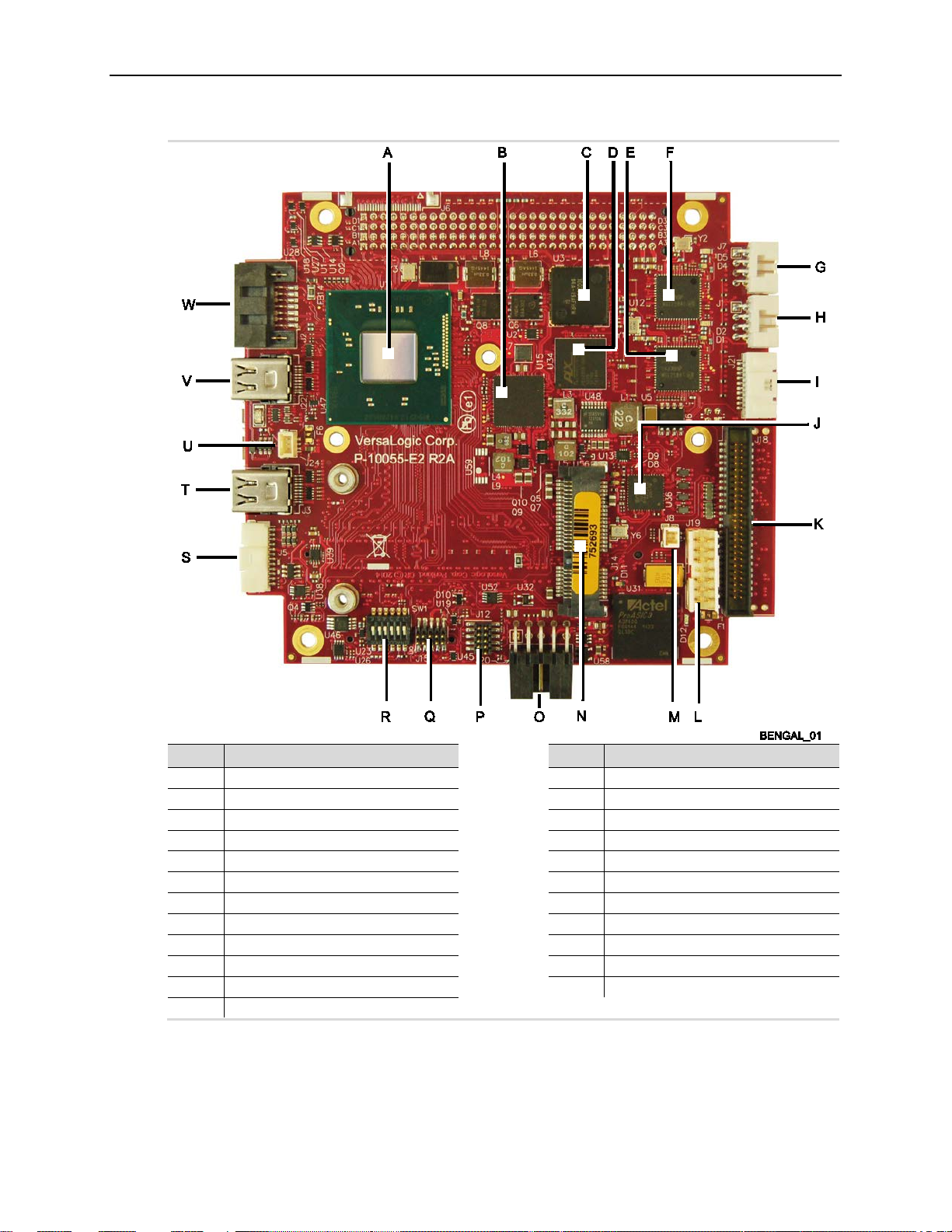
Figure 1. Major Components and Connectors (Top Side) .............................................................................. 2
Figure 2. Major Components and Connectors (Bottom Side) ........................................................................ 3
Figure 3. Bengal Board Block Diagram ......................................................................................................... 4
Figure 4. Be ngal Dimensions and M ounting Holes ........................................................................................ 8
Figure 5. VL-CBR-5015 Dimensions and Mounting Holes ........................................................................... 9
Figure 6. Connector Locations (Top Side) ................................................................................................... 10
Figure 7. Connector Locations (Bottom) ...................................................................................................... 11
Figure 8. VL-CBR-5015 Connectors ............................................................................................................ 13
Figure 9. VL-CBR-2004 Dimensions, Connectors, Jumper Blocks, As-Shipped ......................................... 15
Figure 10. As-Shipped Jumper S ettings ....................................................................................................... 16
Figure 11. Location of SW1 Configuration Switch Block ............................................................................ 17
Figure 12. J20 and VL-CBR-1008 Pin Numbering ...................................................................................... 18
Figure 13. Lo cation and Pin Configuration of J8 Battery Connector ........................................................... 26
Figure 14. VL-CBR-0203 Latching Battery Module .................................................................................... 26
Figure 15. Location of the D11 and D12 LEDs ............................................................................................ 28
Figure 16. Side View of Board Showing Pin Numbers of the Ethernet Connectors ..................................... 33
Figure 17. Location of Ethernet Status LEDs ............................................................................................... 34
Figure 18. E PMe-30EAP CPU Core Temperature Relative to Ambient Temperature ................................. 50
Figure 19. E PMe-30EBP CPU Core Temperature Relative to Ambient Temperature ................................. 51
Figure 20. EPMe-30ECP CPU Core Temperature Relative to Ambient Temperature ................................. 52
Figure 21. Installing the Passive Heat Sink .................................................................................................. 53
Figure 22. Installing the Heat Sink Fan ........................................................................................................ 54
Tables
Table 1: Connector Functions and Interface Cables ...................................................................................... 12
Table 2: VL-CBR-5015 Functions ................................................................................................................ 14
Table 3: Connector Functions and Interface Cables ...................................................................................... 15
Table 4: Jumper Summary ............................................................................................................................. 16
Table 5: Switch Setting Summary ................................................................................................................. 17
Table 6: J20 Main Power Connector Pinout .................................................................................................. 18
Table 7: PCI/104-Express† “B” Connector (PCI) Cur rent Ratings ................................................................ 21
Table 8: PCIe/104† OneBank† Interfaces ...................................................................................................... 21
Table 9: PCI/104-Express† “A” Connector (PCIe/104†) Current Ratings ..................................................... 22
Table 10: J18 User I/O Connector Pinout ..................................................................................................... 23
Table 11: User I/O Connector Signal Routing to VL-CBR-5015 Paddleboard ............................................. 24
Table 12: COM1-2 Pinout – VL-CBR-5015 Connector J3 ........................................................................... 25
Table 13: USB 3.0 J16 Connector Pinout ..................................................................................................... 27
Bengal (VL-EPMe-30) Reference Manual vii
Page 8

Contents
Table 14: Supported Power States ................................................................................................................. 29
Table 15: VGA Video Output Pinout ............................................................................................................ 31
Table 16: mini DisplayPort Connector Pinout ............................................................................................... 32
Table 17: Ethernet Connector Pinout (J1, J7) ............................................................................................... 33
Table 18: Ethernet Status LEDs .................................................................................................................... 34
Table 19: SATA Port Pinout ......................................................................................................................... 35
Table 20: PCIe Mini Card / mSATA Pinout ................................................................................................. 36
Table 21: PCIe Mini Card LED States .......................................................................................................... 38
Table 22: J21 I/O Connector Pinout .............................................................................................................. 39
Table 23: SPX Expansion Bus Pinout ........................................................................................................... 40
Table 24: SPI Contro l Register 1 Bit Assignments ....................................................................................... 42
Table 25: SPI Contro l Register 2 Bit Assignments ....................................................................................... 43
Table 26: CPU T her mal T rip Points .............................................................................................................. 47
Table 27: Temperature Monitoring Programs ............................................................................................... 47
Table 28: Absolute Minimum and Maximum Air Temperatures ................................................................... 48
Table 29: EPMe-30 T hermal Testing Se t up .................................................................................................. 49
Bengal (VL-EPMe-30) Reference Manual viii
Page 9

Intel
†
Atom† “Bay Trail” processor,
Trusted Platform Module
1 1
Description
Features and Construction
The Bengal is a feature-packed single board computer (SBC) designed to support OEM
applications where high reliability and long-term availability are required. Its features include:
Introduction
quad, dual, or single core with
processor clock rates up to 1.91 GHz
(Atom E3845)
Integrated IntelGen7 graphics core,
supports DirectX11, Open GL3, and
H.264, MPEG-2 encoding/decoding
Analog and dual Mini DisplayPort
video outputs
Up to 8 GB DDR3L memory, one
SO-DIMM socket
Two Intel I210-IT-based Ethernet
ports, auto-detect 10Base-T /
100Base-TX / 1000Base-T
One USB 3.0 port and five USB 2.0
ports
The Bengal is compatible with popular operating systems such as Microsoft
Embedded, Linux, VxWorks
VL-EPMe-30 boards are subjected to complete functional testing and are backed by a limited fiveyear warranty. Careful parts sourcing and US-based technical support ensure the highest
possible quality, reliability, service, and product longevity for this exceptional single-board
computer (SBC).
†
, and QNX†.
Two RS-232/422/485 serial ports
Three 8254 timer/counters
Sixteen digital I/O lines
SATA port, 3 Gb/s
Mini PCIe / mSATA socket, supports
Wi-Fi modems, GPS receivers, flash
storage, and other modules
SPX expansion
PC/104 form factor with PCIe/104
OneBank
Customization available
†
expansion
†
Windows†, Windows
†
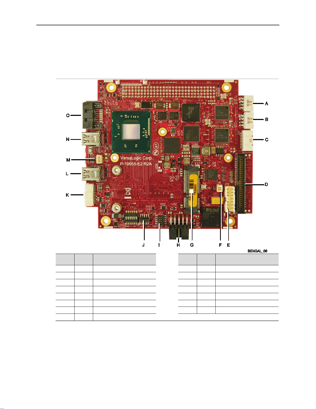
Figure 1 and Figure 2 show the locations of the Bengal board’s connectors and major
components on the top side and bottom side of the board, respectively.
Bengal (VL-EPMe-30) Reference Manual 1
Page 10
Introduction
A
Intel Atom “Bay Trail” SoC
M
External battery connector
B
PMIC power regulator
N
PCIe Minicard (mSATA) connector
C
FPGA O
Power connector
D
PCI Express Switch
P
Reserved
E
Ethernet 1 PHY
Q
Reserved
F
Ethernet 0 PHY
R
Configuration switches
G
Ethernet port 0
S
VGA connector
H
Ethernet port 1
T
Mini DisplayPort1
I
Digital I/O
U
CPU fan connector
J
USB hub device
V
Mini DisplayPort2
K
User I/O connector
W
SATA connector
L
SPX connector
Item Description
Figure 1. Major Components and Connectors (Top Side)
Item Description
Bengal (VL-EPMe-30) Reference Manual 2
Page 11
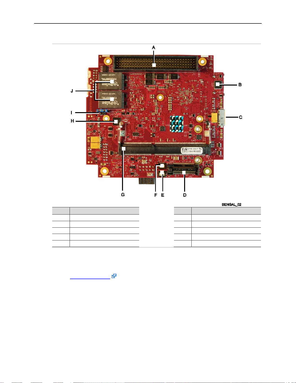
Introduction
A
PCI connector
F
SPI Flash device (backup)
B
Trusted Platform Module (TPM)
G
DDR3 SO-DIMM socket
C
USB 3.0 connector
H
COM port transceiver
D
PCIe/104 OneBank connector
I
COM port jumper block
E
SPI Flash device (primary)
J
Ethernet transformers
Item Description
Figure 2. Major Components and Connectors (Bottom Side)
Technical Specifications
See the Bengal Data Sheet for complete specifications.
Thermal Considerations
The operating temperature for the Bengal is -40 °C to +85 °C, de-rated -1.1 °C per 305m (1,000
ft.) above 2,300m (7,500 ft.). All Bengal models include a rigid-mount heat plate thermal solution.
Refer to Chapter 6 for information on additional thermal solutions.
Item Description
Bengal (VL-EPMe-30) Reference Manual 3
Page 12
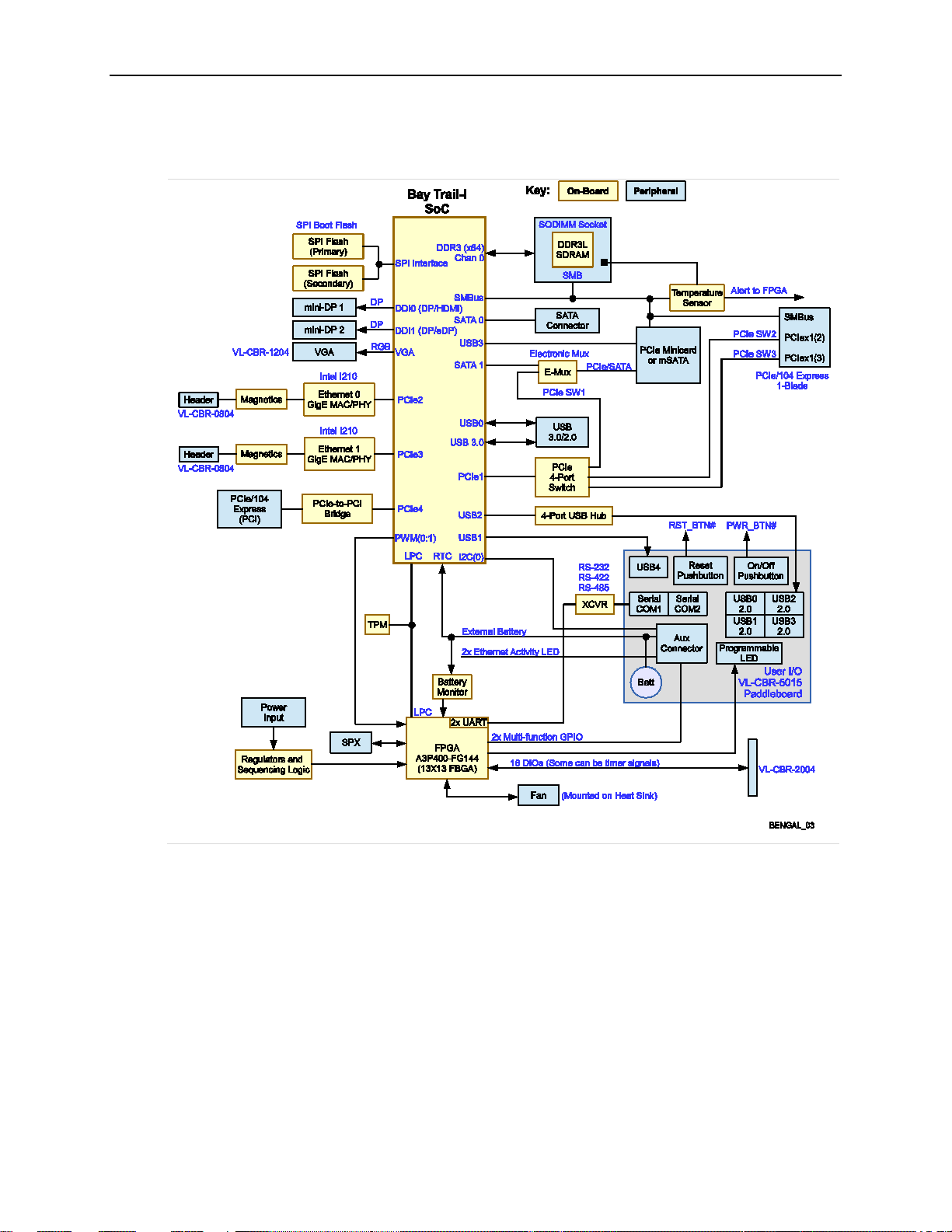
Block Diagram
Introduction
Figure 3. Bengal Board Block Diagram
Bengal (VL-EPMe-30) Reference Manual 4
Page 13
Cautions
Electrostatic discharge (ESD) can damage circuit boards, disk drives, and other
not slide the board over any surface.
After removing the board from its protective wrapper, place the board on a grounded,
static-free surface, component side up. Use an antistatic foam pad if available.
The board should also be protected inside a closed metallic antistatic envelope during
shipment or storage.
The exterior coating on some metallic antistatic bags is sufficiently conductive to cause
excessive battery drain if the bag comes in contact with the bottom side of the Bengal.
Avoid touching the exposed circuitry with your fingers when handling the board. Though
defaults.
All mounting standoffs (four on PC/104 boards, eight on EBX and EPIC boards) should
purposes.
If you are using a CBR-5015 paddleboard with the Bengal board, do not connect an
5015 paddleboard as well.
Electrostatic Discharge
Introduction
CAUTION:
components. The circuit board must only be handled at an ESD workstation. If an
approved station is not available, some measure of protection can be provided by
wearing a grounded antistatic wrist strap. Keep all plastic away from the board, and do
Note:
Handling Care
CAUTION:
it will not damage the circuitry, it is possible that small amounts of oil or perspiration on
the skin could have enough conductivity to cause the contents of CMOS RAM to
become corrupted through careless handling, resulting in CMOS resetting to factory
Earth Ground Requirement
CAUTION:
be connected to earth ground (chassis ground). This provides proper grounding for EMI
Battery Usage
CAUTION:
external battery using the J8 connector. Connecting two batteries to the Bengal board
will damage the batteries and may possibly damage the Bengal board and the CBR-
Bengal (VL-EPMe-30) Reference Manual 5
Page 14

2 2
Initial Configuration
The following components are recommended for a typical development system:
Bengal (VL-EPMe-30) computer
VL-ATX power supply
VL-MM9-xxEBN DDR3 SO-DIMM module (see System RAM)
VGA display (or display with DisplayPort input)
Standard I/O paddleboard (VL-CBR-5015)
USB keyboard and mouse
USB CD-ROM drive (optional)
USB SSD or floppy disk drive (optional)
VL-HD35-xxx SATA hard drive (optional)
The following VersaLogic cables are recommended:
Configuration and Setup
VL-CBR-1204 VGA adapter cable (or VL-EPH-V6 Mini DisplayPort converter)
VL-CBR-0702 or VL-CBR-0701 – SATA data cable
VL-CBR-0401 – ATX to SATA power adapter
VL-CBR-0804 – Ethernet RJ-45 adapter cable
VL-CBR-1008 – Main power cable
You will also need an operating system (OS) installation CD-ROM.
Basic Setup
The following steps outline the procedure for setting up a typical development system. The Bengal
should be handled at an ESD workstation or while wearing a grounded antistatic wrist strap.
Before you begin, unpack the Bengal and accessories. Verify that you received all the items you
ordered. Inspect the system visually for any damage that may have occurred in shipping. Contact
Support@VersaLogic.com immediately if any items are damaged or missing.
Gather all the peripheral devices you plan to attach to the Bengal and their interface and power
cables.
It is recommended that you attach standoffs to the board (see Hardware Assembly) to stabilize
the board and make it easier to work with.
1. Install Memory
Insert the DDR3L DRAM module into the SO-DIMM socket J9 on the bottom side of the
board and latch it into place.
Bengal (VL-EPMe-30) Reference Manual 6
2. Attach Cables and Peripherals
Plug the VGA cable VL-CBR-1204 into socket J5. Attach the cable to the VGA display.
(Alternatively, you can attach a DisplayPort enabled display to one of the Mini DisplayPort
connectors at J3 or J22. The VL-EPH-V6 video adapter card converts DisplayPort output
to LVDS.)
Plug the VL-CBR-5015 paddleboard into socket J18.
Page 15

Configuration and Setup
Plug a USB CD-ROM drive, USB keyboard, and USB mouse into any of the USB
connectors at J4 and J5 of the paddleboard.
Plug the SATA data cable VL-CBR-0702 into socket J2. Attach a hard drive to the
connector on the cable.
Attach the SATA power adapter cable VL-CBR-0401 to the ATX power supply and SATA
drive.
Optionally, attach a LAN cable to either of the Ethernet connectors at J1 or J7 on the
Bengal using the VL-CBR-0804 RJ-45 adapter.
3. Attach Power
Plug the power adapter cable VL-CBR-1008 into socket J20. Attach the motherboard
connector of the ATX power supply to the adapter.
4. Review Configuration
Before you power up the system, double-check all the connections. Make sure all cables
are oriented correctly and that adequate power will be supplied to the VL-EPMe-30 and
peripheral devices.
5. Power On
Turn on the ATX power supply and the video monitor. If the system is correctly
configured, a video signal should be present.
6. Select a Boot Drive
During startup, press <CTRL> <B> to display the boot menu. Insert the OS installation
CD in the CD-ROM drive and select to boot from the CD-ROM drive.
7. Install Operating System
Install the operating system according to the instructions provided by the operating
system manufacturer. (See Operating System Installation.)
BIOS Setup Utility
Refer to the BIOS Reference Manual (available on the Bengal Product Support Page) for
information on accessing and configuring settings in the BIOS Setup utility. All BIOS menus,
submenus, and configuration options are described in the BIOS Reference Manual.
Operating System Installation
The standard PC architecture used on the VL-EPMe-30 makes the installation and use of most of
the standard x86-based operating systems very simple. The operating systems listed on the
VersaLogic OS Compatibility Chart use the standard installation procedures provided by the
maker of the OS. Special optimized hardware drivers for a particular OS, or a link to the drivers,
are available at the Bengal Product Support Page.
Integrator’s Note:
Booting to Windows requires changing the default boot OS in the BIOS Setup utility.
Bengal (VL-EPMe-30) Reference Manual 7
Page 16
3 3
Dimensions and Mounting
Bengal Dimensions
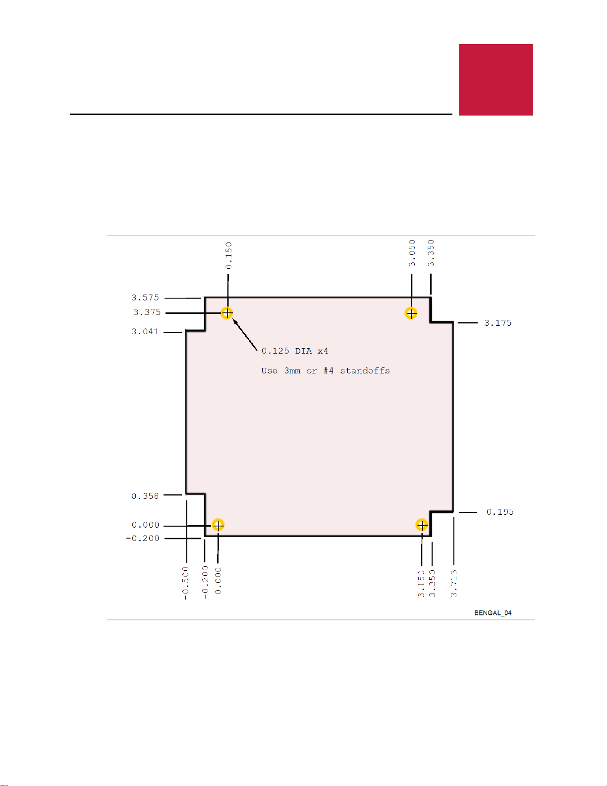
The Bengal complies with PC/104-Plus dimensional standards. Figure 4 shows the board’s
dimensions to help with pre-production planning and layout.
Physical Layout
Bengal (VL-EPMe-30) Reference Manual 8
Figure 4. Bengal Dimensions and Mounting Holes
(Not to scale. All dimensions in inches.)
Page 17
VL-CBR-5015 Dimensions
BENGAL_05
0.065
5.10
5.50
1.17
1.24
1.57
1.95
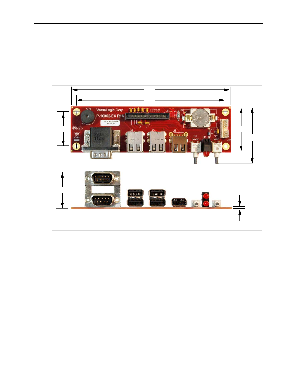
Figure 5 shows the dimensions and mounting holes for the VL-CBR-5015.
All dimensions are in inches
Illustration is not to scale
Physical Layout
Figure 5. VL-CBR-5015 Dimensions and Mounting Holes
Hardware Assembly
The Bengal provides both PCI and PCIe/104 OneBank connectors for adding expansion modules
to the bottom of the stack.
The entire assembly can sit on a tabletop or it can be secured to a base plate. When bolting the
unit down, make sure to secure all four standoffs to the mounting surface to prevent circuit board
flexing. Standoffs are secured to the top circuit board using four pan head screws. Standoffs and
screws are available as part number VL-HDW-105.
An extractor tool is available (part number VL-HDW-203) to separate the expansion modules from
the stack. Use caution when using the extractor tool not to damage any board components.
Bengal (VL-EPMe-30) Reference Manual 9
Page 18
External Connectors
Ref
Des.
Ref
Des.
A
J7
Ethernet Port 0
I J12
Reserved
B
J1
Ethernet Port 1
J J15
Reserved
C
J21
Digital I/O
K J5
VGA Connector
D
J18
User I/O
L J3
Mini DisplayPort1
E
J19
SPX Connector
M J24
CPU Fan
F
J8
External Battery Connector
N J22
Mini DisplayPort2
G
J14
PCIe Minicard (mSATA)
O J2
SATA Connector
H
J20
Power Connector
The User I/O connector (J18) includes signals for COM ports, USB, LEDs, power and reset
buttons, audio, and speaker.
The DisplayPort audio channel works only on the Mini DisplayPort1 connector (J3).
Bengal Connector Locations – Top Side
Physical Layout
Item
Description
Figure 6. Connector Locations (Top Side)
Item
Integrator’s Notes:
Bengal (VL-EPMe-30) Reference Manual 10
Description
Page 19

Bengal Connector Locations – Bottom Side
Ref
Des.
A
J11
PCI B J16
USB 3.0
C
J10
PCIe/104 OneBank
D
J9
DDR3 SO-DIMM
Physical Layout
Item
Figure 7. Connector Locations (Bottom)
Description
Bengal (VL-EPMe-30) Reference Manual 11
Page 20

Physical Layout
(Note)
Cable
FCI 10073599-008LF
20-inch SATA data,
power adapter
J3
Mini DisplayPort 1
— — —
32
J6
Factory Use Only
—
—
—
—
FCI 10073599-008LF
101LF crimp
pin for 28-32 gauge wire
J9
DDR3 SO-DIMM
— — —
20
PCIe/104
Down
mSATA
J15
—
Micro-B cable
COM ports, USB,
input
VL-CBR-1401
VL-CBR-1402
000 (pins)
Molex 501193-2000
pin/crimp
12-inch 1 mm 20-pin DIO
cable and paddleboard
J22
Mini DisplayPort 2
— — —
32
Provided with HDW-407
fan assembly (if used)
Fan power cable with 3pin connector
Bengal Connector Functions and Interface Cables
Table 1 provides information about the function, mating connectors, and transition cables for
Bengal connectors. Page numbers indicate where additional information is available.
Table 1: Connector Functions and Interface Cables
Connector
J1 Gigabit Ethernet 1
J2 SATA
J5
J7 Gigabit Ethernet 0
J8 Battery connector
J10
J11 PCI Stack Down
J12 Factory use only
J14
J16 Micro USB 3.0
Function Mating Connector
VGA
OneBank Stack
PCIe Minicard /
Factory use only
housing, FCI 10044403101LF crimp
Standard SATA
Molex 501330-0500
pin/crimp
housing, FCI 10044403-
Molex 501330-0200
mating connector housi ng
Molex 501334-0100
mating connector cri mp
— — — 21
AMP 1375799-1
—
— — — 36
USB 3.0 Micro-A
Transition
VL-CBR-0804
VL-CBR-0702;
VL-CBR-0401
VL-CBR-1204
VL-CBR-0804
— — 25
— — 21
— — —
— — —
VL-CBR-1015
Cable Description Page
12-inch 8-pin to RJ-45
Ethernet cable
latching; ATX to SATA
12-inch 12-pin to 15-pin
VGA adapter board and
cable
12-inch 8-pin to RJ-45
Ethernet cable
0.5 m USB 3.0 Micro-A t o
33
35
31
33
27
Bengal (VL-EPMe-30) Reference Manual 12
PLED, power LED,
push-button reset,
J18
J19 SPX FCI 89361-714LF
J20 Main power input
J21 Digital I/O
J24 CPU fan
Note: Connector locations J4, J13, J17, and J23 are not used.
power button,
audio jacks, PC
speaker, battery
Oupiin 1204-50G00B2A VL-CBR-5013A
Berg 69176-010
(housing) + Berg 47715-
or
VL-CBR-1008
VL-CBR-2005
—
12-inch 1.27 mm IDC 50pin to 50-pin on VL-CBR5015 paddleboard
2 mm 14-pin IDC, 2 or 4
SPX device cable
Interface from standard
ATX power supply
23
40
18
38
—
Page 21

VL-CBR-5015 Connector Locations
BENGAL_08
SP1
Speaker
J1
Paddleboard
Adapter
B1
Battery
J2
Auxiliary
I/O
S2
Reset
D1
Programmable
LED (Top)
Power LED
(Bottom)
S1
Power
J6
USB5
J5
USB1
(Top)
USB2
(Bottom)
J4
USB3
(Top)
USB4
(Bottom)
J3
COM1 (Top)
COM2 (Bottom)
USB ports 1-4 on the VL-CBR-5015 paddleboard (connectors J4 and J5) are all hubbed, so
which is directly connected to the Bay Trail SoC.
Physical Layout
Figure 8. VL-CBR-5015 Connectors
Integrator’s Note:
throughput may not be optimal. For higher throughput, use the USB 3.0 port or the 5th USB port
on the VL-CBR-5015 paddleboard (at connector J6, intended primarily for a USB Audio device)
Bengal (VL-EPMe-30) Reference Manual 13
Page 22

Physical Layout
Provides power to CMOS RAM and
RTC registers when main power is
off.
Samtec SHF-125-01-F-D-TH
Auxiliary I/O (I2C, GPIO, Ethernet
LED, LED power)
2 mm, 14-pin
keyed header
J3
COM1 (top), COM2 (bottom)
Kycon K42-E9P/P-A4N
Dual DB-9 male
J4
USB3 (top), USB4 (bottom)
USB Type A
USB Host
J5
USB1 (top), USB2 (bottom)
USB Type A
USB Host
J6
USB5
USB Type A
USB Host
Programmable LED (top)
Power LED (bottom)
S1
Power button
Pushbutton
–—
S2
Reset button
Pushbutton
–—
SP1
Speaker
Piezo speaker
–—
VL-CBR-5015 Connector Functions
Table 2: VL-CBR-5015 Functions
Reference Function PCB Connector Description
B1
J1 Paddleboard adapter
J2
D1
–— Back-up battery
• FCI 20021511-00050T1LF
• Oupiin 3216-A50G00SBA
•
FCI 98414-F06-14ULF
LED –—
1.27 mm, 50-pin
keyed header
Bengal (VL-EPMe-30) Reference Manual 14
Page 23

Physical Layout
1
5
1
5
1
5
1
5
0.95
2.37
BENGAL_09
2.95
V6 Jumper Block
J1
J2
J3
J4
J5
1
2
3
VL-CBR-2004B Dimensions and Connectors
The VL-CBR-2005 digital I/O adapter is comprised of the VL-CBR-2005A cable and the VL-CBR2004 I/O paddleboard. The paddleboard provides a screw terminal interface for all digital I/O
lines. Figure 9 shows the VL-CBR-2004 board’s dimensions, connectors, and jumper blocks. All
dimensions are in inches.
Figure 9. VL-CBR-2004 Dimensions, Connectors, Jumper Blocks, As-Shipped
Integrator’s Note:
The jumper blocks should remain in the as-shipped configuration shown in
Table 3 provides information about the function, mating connectors, and the transition cable to the
Bengal.
Table 3: Connector Functions and Interface Cables
Connector Function Mating Connector Transition Cable Cable Description
J1 Digital I/O 1-4 Bare wire, 18–30 AWG — —
J2 Digital I/O 5-8 Bare wire, 18–30 AWG — —
J3 Digital I/O 9-12 Bare wire, 18–30 AWG — —
J4 Digital I/O 13-16 Bare wire, 18–30 AWG — —
J5
Interface to Bengal
board
Molex 501189-2010
2x10 1 mm “pico-clasp”
receptacle
VL-CBR-2005A
Figure 9.
20 position screw
terminal, 12-inch latching
cable to VL-CBR-2004B
I/O board
Bengal (VL-EPMe-30) Reference Manual 15
Page 24

Jumper Blocks
V1
Jumper
Block
BENGAL_10
1 3
2 4
No jumper is required for RS-422. You may use a terminator at the receiver, but it is not required.
A jumper should be used for RS-485 only when the port is used as an endpoint.
Jumper block V1 is located on the bottom side of the board. The board is shipped with two
jumpers installed, but only one side of each jumper is placed on a pin of the V1 jumper block. In
this configuration, the jumpers do not connect any signals. They are placed this way in case you
need to configure the COM ports for RS-485 termination.
Physical Layout
Jumper
Block
V1[1-2]
V1[3-4]
Figure 10. As-Shipped Jumper Settings
Table 4: Jumper Summary
Description
COM1 Rx End-point Termination (see page 24)
In – RS-485 termination
Out – No termination, RS-232 (default)
Places terminating resistor across COM1 RS-485 TXRX+/TXRX- or RS-422 RX+/RXdifferential pair. Jumper must be out for RS-232 operation.
COM2 Rx End-point Termination (see page 24)
In – RS-485 termination
Out – No termination, RS-232 (default)
Places terminating resistor across COM2 RS-485 TXRX+/TXRX- or RS-422 RX+/RX-
differential pair. Jumper must be out for RS-232 operation.
Integrator’s Note:
Bengal (VL-EPMe-30) Reference Manual 16
Page 25

Configuration Switches
BENGAL_11
6 5 4 3 2
1
Off
On
SW1
Switch
Block
Position
quickly.
boot times could increase (by as much as 30 seconds in low temperature environments).
Figure 11 shows the as-shipped switch configuration with all switches in the Off position. The Off
position is toward the center of the board.
Physical Layout
SW1
Switch
Position 1
Position 2
Position 3
Position 4
Position 5
Position 6
Figure 11. Location of SW1 Configuration Switch Block
Table 5: Switch Setting Summary
Description
Clear CMOS RAM and Clears Real-Time Clock (see page 20)
Off – Normal operation (default)
– Clears battery backed up CMOS memory bytes 0xE-0x7F and clears battery backed
On
up RTC registers
No Battery Switch (see Integrator’s Note below)
– A battery is being used (default)
Off
– A battery is not being used
On
Reset BIOS to factory defaults (see page 20)
Off – Normal operation (default)
On – Resets BIOS to factory defaults when the board boots.
For factory use only. Always leave in the Off position.
SPI Flash Security – Not supported.
BIOS select
Off – Primary BIOS (default)
On – Backup BIOS
Integrator’s Note:
If a battery is installed (on the CBR-5015 paddleboard or externally using the J8 connector),
switch position 2 must be set to the Off position. If it is set to On, the battery will discharge
If you don’t use a battery, switch position 2 should be set to the ON position. Otherwise,
Bengal (VL-EPMe-30) Reference Manual 17
Page 26

To prevent severe and possibly irreparable damage to the system, it is critical that the
of the pinout shown in Figure 12.
Pin
Signal
Pin
Signal
Note: This input is only necessary for expansion modules plugged into either
that require this voltage.
4 4
2
4
6
8
10 1 3
5 7 9
J20
VL-CBR-1008
1
3 5 7
9 2 4 6 8
10
Some manufacturers include
a pin
corresponds to pin
power connector pinout
Power Supply
Power Connectors
Main power is applied to the Bengal through a 10-pin polarized connector (J20), with mating
connector Berg 69176-010 (housing) + Berg 47715-000 (pins). See Table 6 for connector pinout
and page 10 for location information.
CAUTION:
power connectors are wired correctly. Make sure to use all +5 VDC pins and all ground
pins to prevent excess voltage drop. The power connector is not fuse or diode
protected. Proper polarity must be followed, otherwise damage will occur. Some
manufacturers include a pin-1 indicator on the crimp housing that corresponds to pin-10
System Features
Table 6: J20 Main Power Connector Pinout
1 Ground 2 +5 VDC
3 Ground 4 +12 V
5 Ground 6 -12 V
7 +3.3 V
9 Ground 10 +5 VDC
the PC104 PCI connector (J11 ) or the PCIe/104 OneBank connector (J10)
Figure 12 shows the VersaLogic standard pin numbering for this type of 10-pin power connector
and the corresponding mating connector.
(Note) 8 +5 VDC
DC
-1 indicator that
-10 of the
DC
DC
(Note)
(Note)
Figure 12. J20 and VL-CBR-1008 Pin Numbering
Bengal (VL-EPMe-30) Reference Manual 18
Page 27

System Features
If the above link to the datasheet becomes inactive, search the internet for “Intel Bay Trail” or
“E3800” and follow the results to the Intel site and datasheet.
Power Requirements
The Bengal requires only +5 VDC (±5 %) for proper operation, as required by the PC/104-Plus
specification. Variable low-voltage supply circuits provide power to the CPU and other on-board
devices.
The exact power requirement of the VL-EPMe-30 depends on several factors, including memory
configuration, CPU clock rate, peripheral connections, and the type and number of expansion
modules and attached devices. For example, driving long RS-232 lines at high speed can
increase power demand.
Power Delivery Considerations
Using the VersaLogic approved power supply (VL-PS200-ATX) and power cable (VL-CBR-1008)
ensures high quality power delivery to the board. Customers who design their own power delivery
methods should take into consideration the guidelines below to ensure good power connections.
In addition, the specifications for typical operating current do not include any off-board power
usage that may be fed through the Bengal power connector. Expansion boards and USB devices
plugged into the board will source additional power through the Bengal power connector.
Do not use wire smaller than 22 AWG. Use high quality UL 1007 compliant stranded
wire.
CPU
The length of the wire should not exceed 18 inches.
Avoid using any additional connectors in the power delivery system.
The power and ground leads should be twisted together, or as close together as possible
to reduce lead inductance.
A separate conductor must be used for each of the power pins.
All power input pins and all ground pins must be independently connected between the
power source and the power connector.
Use a high quality power supply that can supply a stable vol tage while reacting to widely
varying current draws.
The Bengal uses one of three Intel 4th Generation Atom (formerly “Bay Trail”) system-on-chip
(SoC) processors:
E3845 (quad core)
E3826 (dual core)
E3815 (single core)
Each core contains a 512 KB L2 cache. These processors support Intel 64-bit instructions, AES
Instructions, Execute Disable Bit, and Virtualization Technology.
See the Intel Atom Processor E3800 Product Family Datasheet
the CPU.
Note:
Bengal (VL-EPMe-30) Reference Manual 19
for a complete description of
Page 28

System RAM
1.
Power off the Bengal and set SW1 switch position 3 to
2.
Power on the Bengal.
3.
After the system boots, power off the Bengal and set
4.
Power on the Bengal.
1.
Power off the Bengal.
2.
Set SW1 switch position 1 to the On position (toward
3.
Wait at least two seconds and set the switch back to
4.
Power on the Bengal.
The Bengal accepts one 204-pin SO-DIMM memory module (J9 connector) with the following
characteristics:
Size Up to 8 GB, 1066 MHz or 1333 MHz, CPU dependent
Voltage 1.35 V
Type DDR3L (VersaLogic VL-MM9 Series modules)
Resetting BIOS to Factory Defaults
Reset the BIOS to default settings using the following the instructions:
the On position (toward the outer edge of the board).
System Features
the switch back to the Off position (toward the center
of the board).
Clearing CMOS RAM and RTC Registers
Clear the CMOS RAM and RTC registers (which includes the date/time) using the following the
instructions:
the outer edge of the board).
the Off position (toward the center of the board).
Bengal (VL-EPMe-30) Reference Manual 20
Page 29

Real Time Clock (RTC)
There is no on-board battery. The Bengal board will operate without a battery, but to save the
date and time, use a VL-CBR-5015 paddleboard (which includes a battery).
V5
4.0 A
V3P3_ATX
3.0 A
V12_ATX
1.0 A
V12N_ATX
0.5 A
USB 2.0
None supported
SMB
1
PCIe x1
2
Power
+3.3 V, +5 V
ATX Control
No
The Bengal features a real-time clock/calendar (RTC) circuit. The RTC can be set using the
BIOS Setup utility.
The Bengal supplies RTC voltage in S5, S3, and S0 states, but requires an external +2.75 V to
+3.3 V battery connection to maintain RTC functionality and RTC CMOS RAM when the Bengal is
not powered. The battery connection can be made to either (but not both) of the following:
J8 battery connector
Pin 17 of the J18 connector
Integrator’s Note:
Expansion Bus
PCI
System Features
The Bengal provides a legacy stack-down PCI connector at location J11 on the bottom side of the
board. See the PCI sections of the PC/104-Plus Specification for a complete description of this
interface. The BIOS automatically allocates I/O, memory, and interrupt resources.
Table 7: PCI/104-Express† “B” Connector (PCI) Curren t Ratings
Signal Current Rating
PCIe/104† OneBank†
The Bengal provides a high-speed stack-down PCIe/104 OneBank connector at location J10 on
the bottom side of the board. See the PCI/104-Express
description of this interface. Table 8 lists the interfaces provided by the OneBank connector.
Table 8: PCIe/104† OneBank† Interfaces
Feature OneBank
†
& PCIe/104† Specification for a complete
Bengal (VL-EPMe-30) Reference Manual 21
Page 30

System Features
The PCIe/104 OneBank version of the interface does not implement the Bank 2 or Bank 3
connectors.
No attempt should be made to add SUMIT-based products to the OneBank connector. The
warranty.
V5
4.0 A
V3P3_ATX
3.0 A
Integrator’s Note:
CAUTION:
SUMIT interface is not mechanically or electrically compatible with the OneBank interface.
Attempting to use SUMIT expansion modules will damage the OneBank connector and void the
Table 9: PCI/104-Express† “A” Connector (PCIe/104†) Current Ratings
Signal Current Rating
Bengal (VL-EPMe-30) Reference Manual 22
Page 31

RXD1– (RS-422/485)
• CTS1 (RS-232)
RXD1+ (RS-422/485)
TXD1– (RS-422/485)
TXD1+ (RS-422/485)
RXD2– (RS-232)
RXD2+ (RS-422/485)
TXD2– (RS-422/485)
TXD2+ (RS-422/485)
5 5
User I/O Connector
Table 10 lists the pinout of the 50-pin User I/O connector (J18).
Pin Signal Pin Signal
1 Ground 2
Interfaces and Connectors
Table 10: J18 User I/O Connector Pinout
• RXD1 (RS-232)
•
3
•
• TXD1 (RS-232)
5
•
7 Ground 8
• CTS2 (RS-232)
9
•
• TXD2 (RS-232)
11
•
13 Ground 14 Aux I2C Clock
15 Aux I2C Data 16 Ground
17 Bat t ery i nput 18 GPIO2
19 Ground 20 GPIO1
21 +3.3 V power for LEDs 22 Ground
23 Ethernet 0 LED 24 Ethernet 1 LED
25 USB1 +5.0 V 26 USB1 Data +
27 USB1 Data – 28 USB2 +5.0 V
29 USB2 Data + 30 USB 2 Dat a –
31 USB 3 +5.0 V 32 USB3 Data +
33 USB3 Data – 34 USB4 +5.0 V
35 USB4 Data + 36 USB 4 Dat a –
37 +5 V (Protected) 38 Programmable LED
39 Speaker 40 Pushbutton reset
41 Power button 42 Ground
43 USB 5 +5.0 V 44 USB5 Data +
45 USB5 Data – 46 Ground
47 USB 5 +5.0 V 48 No connect
49 No connect 50 Ground
4 Ground
• RTS1 (RS-232)
6
•
• RXD2 (RS-232)
•
10 Ground
• RTS2 (RS-232)
12
•
Bengal (VL-EPMe-30) Reference Manual 23
Page 32

Interfaces and Connectors
2
SP1
AUX I2C Data
S2, J2 Pin 11
S1, J2 Pin 13
B1
J2 Pin 14
19 6 Ground
44
USB5 Data+
20 7 GPIO1
45
USB5 Data-
21 8 3.3 V Power for LEDs
46
Ground
22
12
Ground
47 USB5 +5.0 V
23 9 Ethernet 0 LED
48
Functional
NC
24
10
Ethernet 1 LED
49
NC
50 Ground
Table 11 shows signal routing of the J18 User I/O connector to the VL-CBR-5015 paddleboard.
Table 11: User I/O Connector Signal Routing to VL-CBR-5015 Paddleboard
J18
Pin
10 Ground Ground 35 USB4 Data +
11 TXD2 TxD2- 36 USB4 Data 12 RTS2 TxD2+ 37 +5.0 V (Protect ed)
13
14 1
15 3
16 4 Ground 41
17
18
CBR-5015
Connector
RS-232 RS-422/485 25
1
2 RXD1 RxD1- 27 USB1 Data 3 CTS1 RxD1+ 28
4 Ground Ground 29 USB2 Data +
5 TXD1 TxD1- 30 USB2 Data 6 RTS1 TxD1+ 31
7
8 RXD2 RxD2- 33 USB3 Data 9 CTS2 RxD2+ 34
J3 Top
COM1
J3 Bottom
COM2
2 Ground 38 D1 Programm abl e LED
J2
5 GPIO2 43
J2
Signal
Ground Ground 26 USB1 Data +
Ground Ground 32 USB3 Data +
C Clock
AUX I
Battery Input 42
J18
Pin
39
40
CBR-5015
Connector
J5 Top
USB 1
J5 Bottom
USB 2
J4 Top
USB 3
J4 Bottom
USB 4
J6
USB 5
Signal
USB1 +5.0 V
USB2 +5.0V
USB3 +5.0 V
USB4 +5.0V
Speaker
Pushbutton Reset
Power Button
Ground
USB5 +5.0 V
Not
Serial Ports
The Bengal features two on-board 16550-based serial communications channels located at
standard PC I/O addresses. The serial ports can be operated in RS-232 4-wire, RS-422, or RS485 modes. IRQ lines are chosen in the BIOS Setup utility. Each COM port can be independently
enabled, disabled, or assigned a different I/O base address in the BIOS Setup utility.
COM Port Configuration
Use the BIOS Setup utility to select between RS-232 and RS-422/485 operating modes.
Jumper block V1 configures the serial ports for RS-422/485 operation. See Jumper Summary for
details. The 120 Ω termination resistor should be enabled RS-485 endpoint stations; termination
is optional for RS-422. It should be disabled for all RS-232 modes and RS-485 intermediate
stations.
If RS-485 mode is used, the differential twisted pair (TxD+/RxD+ and TxD-/RxD-) is formed by
connecting plus-to-plus and minus-to-minus.
Bengal (VL-EPMe-30) Reference Manual 24
Page 33

Interfaces and Connectors
COM1
COM2
Top DB9
J3 Pin
Bottom DB9
J3 Pin
1 1 — — — 2 2
RXD*
RxD-
RxD-
3 3 TXD*
TxD-
TxD- 4 4 — — — 5
5
Ground
Ground
Ground 6 6 — — — 7 7 RTS
TxD+
TxD+ 8 8
CTS
RxD+
RxD+ 9 9 — —
—
RS-485 Mode Line Driver Control
The transmit line driver can be automatically turned on and off based on data availability in the
UART output FIFO. This mode can be enabled in the BIOS Setup utility. The transmit line driver
can be enabled in the BIOS Setup utility.
Serial Port Connectors
The pinouts of the DB9M connectors apply to the serial connectors on the VL-CBR-5015
paddleboard.
These connectors use IEC 61000-4-2-rated TVS components to help protect against ESD
damage.
Table 12: COM1-2 Pinout – VL-CBR-5015 Connector J3
RS-232 RS-422 RS-485
I2C
Pins 14 and 15 of I/O connector J18 connect to the first of the seven I2C ports on the Intel Atom
“Bay Trail” processor. The Bengal has a 3.3 V I
interface are included in the Bengal design. The 3.3 V power for this interface is the same as
used for the digital I/O interface. By default, this power is turned off when the processor is in a
sleep state.
GPIO
I/O connector J18 provides two general-purpose I/O signals:
These signals connect to the FPGA on the Bengal.
GPIO1 on pin 20
GPIO2 on pin 18
2
C interface. The required pullups for this
Bengal (VL-EPMe-30) Reference Manual 25
Page 34

Battery Connector
Pin
Signal
CAUTION: If you are using a CBR-5015 paddleboard with the Bengal board, do not
the CBR-5015 paddleboard.
Connector J8 can be used to connect an external battery to the Bengal board. A compatible
battery is available from VersaLogic, part number VL-CBR-0203.
Interfaces and Connectors
2 Battery
1 GND
Figure 13. Location and Pin Configuration of J8 Battery Connector
VL-CBR-0203 External Battery Module
The VL-CBR-0203 is an external battery module compatible with the Bengal board. For more
information, contact Sales@VersaLogic.com.
Figure 14. VL-CBR-0203 Latching Battery Module
connect an external battery using the J8 connector. Connecting two batteries to the
Bengal board will damage the batteries and may possibly damage the Bengal board and
Bengal (VL-EPMe-30) Reference Manual 26
Page 35

Ethernet Status LEDs
J16 Pin
Signal Name
Direction
Function
I/O connector J18 provides two Ethernet Activity LEDs:
Pin 23 (Ethernet 0)
Pin 24 (Ethernet 1)
USB Interfaces
The Bengal includes five USB 2.0 host ports and one USB 3.0 host port. The five USB 2.0 ports
are incorporated into the J18 I/O connector, with standard USB Type A connectors located on the
VL-CBR-5015 paddleboard. Connector J16 on the bottom side of the Bengal provides a USB 3.0
Micro-A (host) connector. Table 13 lists the pinout of the J16 connector.
1 +5V Out +5.0 volts
2 USB- I/O USB 2.0 differential pair negative
3 USB+ I/O USB 2.0 differential pair positive
4 ID In Not used (Note)
5 GND — Ground
6 MICA_SSTX- Out USB 3.0 transmit differential pair negative
7 MICA_SSTX+ Out USB 3.0 transmit differential pair positive
8 GND — Ground
9 MICA_SSRX- In USB 3.0 receive differential pair negative
10 MICA_SSRX+ In USB 3.0 receive differential pair positive
Note: This signal is typically used for On-The-Go (OTG) m ode. The Bengal does not support this mode.
Interfaces and Connectors
Table 13: USB 3.0 J16 Connector Pinout
This interface can operate using either the Atom processor’s EHCI controller or its xHCI controller.
To use the USB 3.0 Super Speed mode, the xHCI controller must be used. USB controller
selection is set in the BIOS. By default, EHCI is used. Some older operating systems (such as
MS-DOS) may not support xHCI.
The VersaLogic VL-CBR-1015 cable is a USB 3.0 Micro-A to Micro-B adapter. The VL-CBR-1015
cable can be used to connect the Bengal to any certified USB 3.0 hubs.
Bengal (VL-EPMe-30) Reference Manual 27
Page 36

LEDs
Programmable LED
Connector J18 includes an output signal for a programmable LED. Connect the cathode of the
LED to J18 pin 38; connect the anode to +5 V. An on-board 332 Ω resistor limits the current to
15 mA. A programmable LED is provided on the VL-CBR-5015 paddleboard. The programmable
LED is the top LED at position D1.
SATA/mSATA Acti vi ty LED
Figure 15 shows the location (D12) of the SATA/mSATA activity blue LED. This LED indicates
activity on either the SATA or the mSATA interface. Not all mSATA drives provide this disk
activity signal.
Power LEDs
Figure 15 shows the location (D11) of the dual green/yellow LED. This dual LED indicates the
following:
Interfaces and Connectors
The green LED illuminates when all power rails are within specified limits and indicates
that the board is in the S0 power state. If any power rail is not within specified limits, the
green LED will not illuminate. The green LED blinks at a slow rate when the processor is
in a sleep or hibernate mode indicating that the sustain rail power is still within specified
limits
The yellow LED is a fault indicator that illuminates if there is a problem with the processor
booting. (Software can also be used to turn on this LED to indicate a major software
failure.)
The power LED on the VL-CBR-5015 indicates that the paddleboard is being powered by the 5 V
supply (though it does not indicate that all S0 power supplies are within specified limits). The LED
is lit only when the board is in the S0 power state. If the board enters a Sleep or Hibernate mode,
the LED will not be lit.
Figure 15. Location of the D11 and D12 LEDs
Bengal (VL-EPMe-30) Reference Manual 28
Page 37

Power Button
All processor caches are flushed, and the CPUs stop executing instructions. Power to
may be powered down.
Hibernation or Suspend-to-Disk. All content of main memory is saved to non-volatile
memory, such as a hard drive, and is powered down.
Soft Off. Almost the same as G3 Mechanical Off, except that the power supply still
device.
Connector J18 includes an input for a power button. Shorting J18 pin 41 to ground causes the
board to enter an S5 power state (similar to the Windows Shutdown state). Shorting it again
returns the board to the S0 power state and reboots the board. The button can be configured in
Windows to enter an S3 power state (Sleep, Standby, or Suspend-to-RAM), an S4 power state
(Hibernate or Suspend-to-Disk), or an S5 power state (Shutdown or Soft-Off).
The input can be connected to ground using the normally open contacts of a pushbutton switch or
a relay, or with a switching transistor (open-collector or open-drain) capable of sinking 1 mA. The
input must be driven to a voltage between 0 V and 500 mV to be recognized by the Bengal. Do
not add an external pull-up resistor to this signal.
This connector uses IEC 61000-4-2-rated TVS components to help protect against ESD damage.
A power button is provided on the VL-CBR-5015 paddleboard (S1). Header J2 on the
paddleboard also provides a power button signal on pin 13 and ground on pin 14.
In configurations where a power button is not connected to the board, if the system is put into an
S5 state, power can be restored by turning off the power supply and turning it back on. This
behavior is set by default in the BIOS.
Interfaces and Connectors
Supported Power States
Table 14 lists the board’s supported power states.
Table 14: Supported Power States
Power state Description
S0 (G0) Working
S1 (G1-S1)
S3 (G1-S3) Commonly referred to as Standby, Sleep, or Suspend-to-RAM. RAM remains powered.
S4 (G1-S4)
S5 (G2)
G3 Mechanical off (ATX supply switch turned off).
the CPUs and RAM is maintained. Devices that do not indicate they must remain on
provides power, at a minimum, to the power button to allow return to S0. A full reboot is
required. No previous content is retained. Other components may remain powered so
the computer can "wake" on input from the keyboard, clock, modem, LAN, or USB
Bengal (VL-EPMe-30) Reference Manual 29
Page 38

Pushbutton Reset
Holding the reset button in when powering on the board prevents booting and requires a repower. Make sure the reset button is not being asserted low when powering on the board.
Connector J18 includes an input for a pushbutton reset switch. Shorting J18 pin 40 to ground
causes the Bengal to reboot.
The input can be connected to ground using the normally open contacts of a pushbutton switch or
a relay, or with a switching transistor (open-collector or open-drain) capable of sinking 1 mA. The
input must be driven to a voltage between 0 V and 500 mV to be recognized by the Bengal. Do
not add an external pull-up resistor to this signal.
This connector uses IEC 61000-4-2-rated TVS components to help protect against ESD damage.
A reset button is provided on the VL-CBR-5015 paddleboard (S2). Header J2 on the paddleboard
also provides a reset signal on pin 11 and ground on pin 14.
Note:
Speaker
Interfaces and Connectors
Connector J18 includes a speaker output signal at pin 39. The VL-CBR-5015 paddleboard
provides a Piezo-electric speaker (as shown in Figure 8).
Bengal (VL-EPMe-30) Reference Manual 30
Page 39

Video Interfaces
Pin
1
GND
Ground 6
2
RED
Red Video
1
3
GND
Ground 7
4
GREEN
Green Video
2 5
GND
Ground 8
6
BLUE
Blue Video
3 7
GND
Ground 10
8
HSYNC
Horizontal Sync
13
9
GND
Ground 5
10
VSYNC
Vertical Sync
14
11
SCL
DDC Serial Data Line Clock
15
12
SDA
DDC Serial Data Line
12
The Bengal incorporates the Intel Gen-7 graphics core with four Execution Units and Turbo Boost.
It supports two independent displays. It also supported formats including DirectX 11, OpenGL 3,
VP8, MPEG2, H.264, VC1, 2 HD streams (1080p@30fps), Flash and WMP support.
Analog and dual mini DisplayPort video interfaces support Extended Desktop, Clone, and Twin
display modes.
The optional VL-EPH-V6 video adapter card converts DisplayPort output to LVDS for flat panel
operation.
VGA Connector
An adapter cable, VL-CBR-1204, is available to translate VGA connector J5 into a standard 15-pin
D-Sub SVGA connector. The VGA port supports resolutions up to 2560 x 1600 at 60 Hz. This
connector is protected against ESD damage.
When the Bengal is booted, the BIOS tests for a video monitor attached to the VGA port. If a
monitor is not detected during this test, the VGA signals are disabled.
Interfaces and Connectors
Table 15: VGA Video Output Pinout
J5 Pin Signal name Function
Mini DB15
Bengal (VL-EPMe-30) Reference Manual 31
Page 40

Interfaces and Connectors
J3, J22 Pin
Signal Name
J3, J22 Pin
Signal Name
1
GND
2
HOT PLUG DETECT
3
ML_LANE0_P
4
CONFIG 1
5
ML_LANE0_N
6
CONFIG 2
7
GND
8
GND
9
ML_LANE1_P
10
ML_LANE3_P
11
ML_LANE1_N
12
ML_LANE3_N
13
GND
14
GND
15
ML_LANE2_P
16
AUX_CH_P
17
ML_LANE2_N
18
AUX_CH_N
19
RTN
20
DP_POWER
DisplayPort
Two DisplayPorts are provided using two 20-pin mini DisplayPort connectors at locations J3 and
J22. DisplayPort consists of three interfaces:
Main Link – transfers high-speed isochronous video and audio data.
Auxiliary channel – used for link management and device control; the EDID is read over
this interface.
Hot Plug Detect – indicates that a cable is plugged in.
DisplayPort1 (J3) is the DP++ port that presently supports audio signaling.
Table 16: mini DisplayPort Connector Pinout
Console Redirection
The Bengal board can be configured for remote access by redirecting the console to a serial
communications port. The BIOS Setup utility and some operating systems (such as MS-DOS) can
use this console for user interaction.
The default settings for the redirected console are 115.2 kbps, 8 data bits, 1 stop bit, no parity,
and no flow control.
Bengal (VL-EPMe-30) Reference Manual 32
Page 41

Ethernet
VL-CBR-0804
RJ-45 Pin
1
- Auto Switch (Tx or Rx)
BI_DD-
8
2
+ Auto Switch (Tx or Rx)
BI_DD+
7
3
- Auto Switch (Tx or Rx)
BI_DB-
6
4
+ Auto Switch (Tx or Rx)
BI_DB+
3
5
- Auto Switch (Tx or Rx)
BI_DC-
5
6
+ Auto Switch (Tx or Rx)
BI_DC+
4
7
- Auto Switch (Tx or Rx)
BI_DA-
2
8
+ Auto Switch (Tx or Rx)
BI_DA+
1
The Bengal features two on-board Intel I210-IT Gigabit Ethernet controllers. The controllers
provide a standard Ethernet interface for 1000Base-T, 100Base-TX, and 10Base-T applications.
Drivers are available to support a variety of operating systems. These interfaces are protected
against ESD damage.
Ethernet Connectors
Two Ethernet interfaces are provided at connector locations J7 (Ethernet 0) and J1 (Ethernet 1).
The I210-IT Ethernet controller auto-negotiates connection speed. VersaLogic cable VL-CBR0804 adapts the 8-pin Ethernet connector to an RJ-45 connector. Table 17 lists the pinout of the
J1 and J7 Ethernet connectors. Figure 16 is a side view of the board showing the Ethernet
connectors and their pin configurations.
Interfaces and Connectors
Table 17: Ethernet Connector Pinout (J1, J7)
J1, J7 Pin 10/100 Signal Name 10/100/1000 Signal Name
Figure 16. Side View of Board Showing Pin Numbers of the Ethernet Connectors
Bengal (VL-EPMe-30) Reference Manual 33
Page 42

Interfaces and Connectors
Port/LED
Color
State
Description
Ethernet Status LEDs
On-board status LEDs are provided at locations D5 (single yellow) and D4 (dual green/yellow) for
Ethernet 0, and D2 (single yellow) and D1 (dual green/yellow) for Ethernet 1. Table 18 lists the
states of the Ethernet status LEDs. Figure 17 shows the locations of the Ethernet status LEDs.
Table 18: Ethernet Status LEDs
• Ethernet 0 – LED D5
• Ethernet 1 – LED D2
• Ethernet 0 – LED D4
• Ethernet 1 – LED D1
Yellow
(Activity)
Green/Yellow
(Link Speed)
Figure 17. Location of Ethernet Status LEDs
On Cable connected (blinks with activity)
Off Cable not connected
Yellow 1 Gbps speed
Green 100 Mbps speed
Off 10 Mbps speed or cable not connected
Bengal (VL-EPMe-30) Reference Manual 34
Page 43

SATA Port
SATA Pin
Signal Name
Function
The Bengal provides one 3 GB/s SATA port (J2). The SATA connector is a standard 7-pin rightangle connector with latching capability.
Power to the SATA drive is provided by the ATX power supply. Note that the standard SATA drive
power connector is different from the typical 4-pin Molex connector used on IDE drives. Most
current ATX power supplies provide SATA connectors, and many SATA drives provide both types
of power connectors. If the power supply you are using does not provide SATA connectors,
adapters are available.
Interfaces and Connectors
Table 19: SATA Port Pinout
1 GND Ground
2 TX+ Transmit +
3 TX- Transmit 4 GND Ground
5 RX- Receive 6 RX+ Receive +
7 GND Ground
Bengal (VL-EPMe-30) Reference Manual 35
Page 44

PCIe Mini Card / mSATA
Pin
Signal Name
Function
Signal Name
Function
The socket at location J14 accepts a full-height PCI Express Mini Card or an mSATA module.
The PCIe Mini Card interface includes one PCIe x1 lane, one USB 2.0 channel, and the SMBus
interface. The socket is compatible with plug-in Wi-Fi modems, GPS receivers, Flash data
storage, and other cards for added flexibility. An Intel
Express Mini Card (VL-MPEe-W2) is available from VersaLogic. A Wi-Fi antenna (VL-CBRANT01) and a 12-inch Wi-Fi card to bulkhead RP-SMA transition cable (VL-CBR-0201) are also
available. For more information, contact Sales@VersaLogic.com.
The VL-MPEs-F1E series of mSATA modules provide flash storage of 4 GB, 16 GB, or 32 GB.
To secure a Mini Card or mSATA module to the on-board standoffs, use two M2.5 x 6mm pan
head Philips nylon screws. These screws are available in quantities of 10 in the VL-HDW-108
hardware kit from VersaLogic.
Table 20: PCIe Mini Card / mSATA Pinout
Interfaces and Connectors
†
Centrino† Advanced-N 6205 Wireless
J14
1 WAKE# Wake Reserved Not connected
2 3.3VAUX 3.3V auxiliary source +3.3V 3.3V source
3 NC Not connected Reserved Not connected
4 GND Ground GND Ground
5 NC Not connected Reserved Not connected
6 1.5V 1.5V power +1.5V 1.5V power
7 NC Not connected Reserved Not connected
8 NC Not connected Reserved Not connected
9 GND Ground GND Ground
10 NC Not connected Reserved Not connected
11 REFCLK- Reference clock input – Reserved Not connected
12 NC Not connected Reserved Not connected
13 REFCLK+ Reference clock input + Reserved Not connected
14 NC Not connected Reserved Not connected
15 GND Ground GND Ground
16 NC Not connected Reserved Not connected
17 NC Not connected Reserved Not connected
18 GND Ground GND Ground
19 NC Not connected Reserved Not connected
20 W_DISABLE# Wireless disable Reserved Not connected
21 GND Ground GND Ground
22 PERST# Card reset Reserved Not connected
23 PERn0 PCIe receive – +B Host receiver diff. pair +
24 3.3VAUX 3.3V auxiliary source +3.3V 3.3V source
25 PERp0 PCIe receive + -B Host receiver diff. pair –
26 GND Ground GND Ground
PCIe Mini Card
PCIe Mini Card
mSATA
mSATA
Bengal (VL-EPMe-30) Reference Manual 36
Page 45

Interfaces and Connectors
Pin
Signal Name
Function
Signal Name
Function
J14
27 GND Ground GND Ground
28 1.5V 1.5V power +1.5V 1.5V power
29 GND Ground GND Ground
30 SMB_CLK SMBus clock Two Wire I/F Two wire I/F clock
31 PETn0 PCIe transmit – -A Host transmitter diff. pair –
32 SMB_DATA SMBus data Two Wire I/F Two wire I/F data
33 PETp0 PCIe transmit + +A Host transmitter diff. pair +
34 GND Ground GND Ground
35 GND Ground GND Ground
36 USB_D- USB data – Reserved Not connected
37 GND Ground GND Ground
38 USB_D+ USB data + Reserved Not connected
39 3.3VAUX 3.3V auxiliary source +3.3V 3.3V source
40 GND Ground GND Ground
41 3.3VAUX 3.3V auxiliary source +3.3V 3.3V source
42 LED_WWAN# Wireless WAN LED Reserved Not connected
43 GND mSATA detect 1 GND/NC Ground/not connected 2
44 LED_WLAN# Wireless LAN LED Reserved Not connected
45 NC Not connected Vendor Not connected
46 LED_WPAN# Wireles s PAN LED Reserved Not connected
47 NC Not connected Vendor Not connected
48 1.5V 1.5V power +1.5V 1.5V power
49 Reserved Reserved DA/DSS Device activity 3
50 GND Ground GND Ground
51 Reserved Reserved GND Ground 4
52 3.3VAUX 3.3V auxiliary source +3.3V 3.3V source
PCIe Mini Card
PCIe Mini Card
mSATA
mSATA
Notes:
1. This pin is not grounded on the Bengal since it can be used to detect the presence of an mSATA
module versus a PCIe Mini Card. Grounding this pin is available as an option on custom
boards.
2. This pin is not grounded on the Bengal to make it available for mSATA module detection.
3. This signal drives the blue LED activity indicator at location D12 in the lower right corner of the
board (refer to
mSATA module.
4. Some PCIe modules use this signal as a second Mini Card wireless disable input. On the
Bengal, this signal is available for use for mSATA versus PCIe Mini Card detection. There is an
option in the BIOS Setup utility for setting the mSATA detection method.
Figure 15). This LED lights with mSATA disk activity, if supported by the
Bengal (VL-EPMe-30) Reference Manual 37
Page 46

Interfaces and Connectors
LED
Color
Status (when lit)
device.
The 3.3 V power to the Mini Card can be controlled by the FPGA. By default, the power is always
always turned off in sleep modes.
PCIe Mini Card LEDs
Two dual-colored PCIe Mini Card LEDs are provided on the Bengal at locations D8 and D9. Table
21 lists the states of the LEDs.
Table 21: PCIe Mini Card LED States
Green Activity on Wireless WAN (Note)
D8
Yellow Activity on Wireless LAN (Note)
Green Activity on Wireless PAN (Note)
D9
Note: These LEDs will illuminate when the associat ed device is installed
and capable of transmit t i ng. Their function is determined by the installed
Integrator’s Note:
on, but there is a register setting that turns this power off in sleep modes. The 1.5 V power is
Digital I/O
The 20-pin I/O connector (J21) incorporates 16 digital I/O (DIO) lines that are independently
configurable as an input or output. DIO inputs can be set for normal or inverted level. DIO
outputs can be set to be normal HIGH or LOW state. There are pull-up resistors to +3.3 V on all
DIO lines. The pull-ups implemented — in the FPGA — can range in value from 20 kΩ to 40 kΩ.
After reset, the DIO lines are set as inputs with pull-ups that will be detected as a HIGH state to
external equipment.
VersaLogic provides a set of application programming interface (API) calls for managing the DIO
lines. See the VersaAPI Support Page
Yellow
Illuminates when the 3.3 V power to the Mini
Card is on. It alerts users to not hot-plug the
Mini Card. By default, Mini Card power stays
on when the processor is in sleep modes.
for information.
Table 22 shows the function of each J21 pin and how they are routed to the paddleboard.
Bengal (VL-EPMe-30) Reference Manual 38
Page 47

Table 22: J21 I/O Connector Pinout
VL-CBR-2004B
Connector
VL-CBR-2004B
Pin
1
Digital I/O 1 5
2
Digital I/O 2 4
3
Digital I/O 3
J1
3
4
Digital I/O 4 1
5
Ground 2
6
Digital I/O 5 5
7
Digital I/O 6 4
8
Digital I/O 7
J2
2
9
Digital I/O 8 1
10
Ground 3
11
Digital I/O 9 (optional Timer Channel 5 Output)
5
12
Digital I/O 10 (optional Timer Channel 5 Output)
3
13
Digital I/O 11 (optional Timer Channel 3 Gate Input)
J3
2
14
Digital I/O 12 (optional Timer Channel 4 Gate Input)
1
15
Ground 4
16
Digital I/O 13 (optional Timer 3 Output)
4
17
Digital I/O 14 (optional Timer 3 Input)
3
18
Digital I/O 15 (optional Timer 4 Output)
J4
2
19
Digital I/O 16 (optional Timer 4 Input)
1
20
Ground 5
Do not connect the DIO signals to external +5 V devices; doing so will damage the FPGA and
void the warranty.
J21 Pin Signal
Interfaces and Connectors
FPGA registers control the mode on pins 11-14 and 16-19. By default, they are DIOs. There are
FPGA register settings to select the timer signals in 4-signal mode (pins 16-19) and 8-signal mode
(11-15 and 16-19).
DIO Guidelines
Consider the following guidelines when using the Bengal DIO lines.
Voltage
The Bengal DIO lines are 3.3 V Low-voltage TTL (LVTTL) compatible DIOs capable of
sourcing/sinking up to 4 mA of current. Level shifting or current limiting is necessary when
connecting signals with different voltage rails.
CAUTION:
Bengal (VL-EPMe-30) Reference Manual 39
Page 48

Interfaces and Connectors
Function
V5_0
+5 V (Protected)
SCLK
Serial Clock
Ground
Serial Data In
Ground
Serial Data Out
Ground
Chip Select 0
Chip Select 1
Chip Select 2
SS3#
Chip Select 3
GND
Ground
Power States
CPU power states will affect voltage rails driving DIO circuits as described below:
DIOs and their pull-up resistors will remain powered in all CPU power states (except when
power is turned off).
Power control during CPU power states on user devices connected to DIO lines is
dependent on the application design. These external devices would likely remain
powered unless a power-down mechanism is designed into the system.
Care must be taken when powered DIO signals are connected to un-powered DIO
signals. Significant voltage and current can be leaked from a powered system to an unpowered system causing unpredictable results. Current limiting and/or diode isolation can
help.
Cables
Cabling issues will affect the usable speed of DIO signals.
These are single-ended drivers/receivers.
Cabling crosstalk can be a problem with fast edge rates. The DIOs are slew-rate limited
and have 50 Ω source terminators to minimize crosstalk and reflections.
SPX Expansion Bus
Up to four serial peripheral expansion (SPX) devices can be attached to the Bengal at connector
J19 using a VL-CBR-1401 or VL-CBR-1402 cable. The SPX interface provides the standard
serial peripheral interface (SPI) signals: SCLK, MISO, and MOSI, as well as four chip selects,
SS0# – SS3#, and an interrupt input, SINT#.
The +5 V power provided to pins 1 and 14 of J19 is protected by a 1 A resettable fuse.
Pin
1
3
5
7
9
11
Signal/
GND
GND
GND
SS1#
Table 23: SPX Expansion Bus Pinout
Pin Signal/Function
2
4
6
8
10
12
MISO
MOSI
SS0#
SS2#
13
SINT#
Interrupt Input
14
V5_0
+5 V (Protected)
Bengal (VL-EPMe-30) Reference Manual 40
Page 49

Interfaces and Connectors
SPI is, in its simplest form, a three wire serial bus. One signal is a clock, driven only by the
permanent master device on-board. The others are Data In and Data Out with respect to the
master. The SPX implementation adds additional features, such as chip selects and an interrupt
input to the Master. The master device initiates all SPI transactions. A slave device responds
when its chip select is asserted and it receives clock pulses from the master.
The SPI clock rate can be software configured to operate at speeds between 1 MHz and 8 MHz.
Because this clock is divided from a 33 MHz PCI clock, the actual generated frequencies are not
discrete integer MHz frequencies. All four common SPI modes are supported through the use of
clock polarity and clock idle state controls.
VersaLogic SPX Expansion Modules
VersaLogic offers several SPX modules that provide a variety of standard functions, such as
analog input, digital I/O, CANbus controller, and others. These are small boards (1.2 x 3.78
inches) that can mount on the PC/104 stack, using standard standoffs, or up to two feet away
from the baseboard. For more information, contact VersaLogic at Info@VersaLogic.com.
Bengal (VL-EPMe-30) Reference Manual 41
Page 50

Interfaces and Connectors
Bit
Mnemonic
Description
SPI Clock Polarity – Sets the SCLK idle state.
1 = SCLK idles high
SPI Clock Phase –
1 = Data read on falling edge
1 = Manual
SS2
SS1
SS0
Slave Select
SPI Registers
A set of control and data registers are available for SPI transactions. The following tables
describe the SPI control registers (SPICONTROL and SPISTATUS) and data registers
(SPIDATA3-0).
SPICONTROL (READ/WRITE) C88h
D7 D6 D5 D4 D3 D2 D1 D0
CPOL CPHA SPILEN1 SPILEN0 MAN_SS SS2 SS1 SS0
Table 24: SPI Control Register 1 Bit Assignments
D7 CPOL
D6 CPHA
D5-D4 SPILEN(1:0)
D3 MAN_SS
D2-D0 SS(2:0)
0 = SCLK idles low
0 = Data read on rising edge
SPI Frame Length – Sets the SPI frame length. This selection works in
manual and auto slave select modes.
SPILEN1 SPILEN0 Frame Length
0
0
1
1
SPI Manual Slave Select Mode – This bit determines whether the slave
select lines are controlled through the user software or are automatically
controlled by a write operation to SPIDATA3 (CADh). If MAN_SS = 0, then
the slave select operates automatically; if MAN_SS = 1, then the slave select
line is controlled manually through SPICONTROL bits SS2, SS1, and SS0.
0 = Automatic, default
SPI Slave Select – These bits determine which slave select will be asserted.
The SSx# pin on the baseboard will be directly controlled by these bits when
MAN_SS = 1.
ADIOMODE = 0 (default mode)
0
0
0
0
1
1
1
1
Sets the SCLK edge on which valid data will be read.
0
1
0
1
0
0
1
1
0
0
1
1
0
1
0
1
0
1
0
1
None, port disabled
SPX Slave Select 0, J28 pin-8
SPX Slave Select 1, J28 pin-9
SPX Slave Select 2, J28 pin-10
SPX Slave Select 3, J28 pin-11
Not supported
Not supported
Not supported
8-bit
16-bit
24-bit
32-bit
Bengal (VL-EPMe-30) Reference Manual 42
Page 51

Interfaces and Connectors
Bit
Mnemonic
Description
be set to enable SPI IRQ functionality.
IRQSEL1
IRQSEL0
IRQ
1
1
IRQ10
SPI SCLK Frequency – These bits set the SPI clock frequency.
SPICLK1
SPICLK0
Frequency (MHz)
1
1
8.25
settings must be configured for the desired ISA IRQ.
1 = SPIDATA data is right-shifted (LSbit first)
cleared.
SPISTATUS (READ/WRITE) C89h
D7 D6 D5 D4 D3 D2 D1 D0
IRQSEL1 IRQSEL0 SPICLK1 SPICLK0 HW_IRQ_EN LSBIT_1ST HW_INT BUSY
Table 25: SPI Control Register 2 Bit Assignments
IRQ Select – These bits select which IRQ is asserted when a hardware
interrupt from a connected SPI device occurs. The HW_IRQ_EN bit must
D7-D6 IRQSEL(1:0)
D5-D4 SPICLK(1:0)
D3 HW_IRQ_EN
D2 LSBIT_1ST
D1 HW_INT
0
0
1
0
0
1
Hardware IRQ Enable – Enables or disables the use of the selected IRQ
(IRQSEL) by an SPI device.
0 = SPI IRQ disabled, default
1 = SPI IRQ enabled
Note: The selected IRQ is shared with PC/104 ISA bus devices. CMOS
SPI Shift Direction – Controls the SPI shift direction of the SPIDATA
registers. The direction can be shifted toward the least significant bit or the
most significant bit.
0 = SPIDATA data is left-shifted (MSbit first), default
SPI Device Interrupt State – This bit is a status flag that indicates when the
hardware SPX signal SINT# is asserted.
0 = Hardware interrupt on SINT# is de-asserted
1 = Interrupt is present on SINT#
This bit is read-only and is cleared when the SPI device’s interrupt is
0
1
0
0
1
0
IRQ3
IRQ4
IRQ5
1.03125
2.0625
4.125
SPI Busy Flag – This bit is a status flag that indicates when an SPI
transaction is underway.
D0 BUSY
0 = SPI bus idle
1 = SCLK is clocking data in and out of the SPIDATA registers
This bit is read-only.
Bengal (VL-EPMe-30) Reference Manual 43
Page 52

Interfaces and Connectors
SPIDATA0 (READ/WRITE) C8Ah
D7 D6 D5 D4 D3 D2 D1 D0
MSbit LSbit
SPIDATA1 (READ/WRITE) C8Bh
D7 D6 D5 D4 D3 D2 D1 D0
MSbit LSbit
SPIDATA2 (READ/WRITE) C8Ch
D7 D6 D5 D4 D3 D2 D1 D0
MSbit LSbit
SPIDATA3 (READ/WRITE) C8Dh
D7 D6 D5 D4 D3 D2 D1 D0
MSbit LSbit
SPIDATA3 contains the most significant byte (MSB) of the SPI data word. A write to this register
initiates the SPI clock and, if the MAN_SS bit = 0, also asserts a slave select to begin an SPI bus
transaction. Increasing frame sizes from 8-bit uses the lowest address for the least significant
byte of the SPI data word; for example, the LSB of a 24-bit frame would be SPIDATA1. Data is
sent according to the LSBIT_1ST setting. When LSBIT_1ST = 0, the MSbit of SPIDATA3 is sent
first, and received data will be shifted into the LSbit of the selected frame size set in the SPILEN
field. When LSBIT_1ST = 1, the LSbit of the selected frame size is sent first, and the received
data will be shifted into the MSbit of SPIDATA3.
Data returning from the SPI target will normally have its most significant data in the SPIDATA3
register. An exception occurs when LSBIT_1ST = 1 to indicate a right-shift transaction. In this
case, the most significant byte of an 8-bit transaction will be located in SPIDATA0, a 16-bit
transaction’s most significant byte will be located in SPIDATA1, and a 24-bit transaction’s most
significant byte will be located in SPIDATA2
.
Bengal (VL-EPMe-30) Reference Manual 44
Page 53

By itself, the heat plate is not a complete thermal solution. Integrators should either implement a
85 ºC.
The heat plate is permanently affixed to the Bengal and must not be removed. Removal of the
voids the product warranty and can damage the CPU.
6
Thermal Considerations
This chapter discusses the following topics related to thermal issues:
Selecting the correct thermal solution for your application (begins below)
EPMe-30 thermal characterization (begins on page 49)
Installing the passive (HDW-406 heat sink) and active (HDW-407 fan) thermal solutions
available from VersaLogic (begins on page 53)
Selecting the Correct Thermal Solution for Your Application
This section provides guidelines for the overall system thermal engineering effort.
Heat Plate
The heat plate supplied with the Bengal is the basis of the thermal solution. The heat plate draws
heat away from the CPU chip as well as other critical components such as the power supply /
management unit, the PCIe-to-PCI Bridge, and the Ethernet interfaces. Other components rely
on the ambient air temperature being maintained at or below the maximum specified 85 ºC.
The heat plate is designed with the assumption that the user’s thermal solution will maintain the
top surface of the heat plate at 90 ºC or less. If that temperature threshold is maintained, the
CPU (and the other noted components) will remain safely within their operating temperature limits.
CAUTION:
thermal solution using the accessories available from VersaLogic or develop their own thermal
solution that attaches to the heat plate, suitable for environments in which the EPMe-30 will be
used. As stated above, any thermal solution must be capable of keeping the top surface of the
heat place at or below 90 ºC and the air surrounding the components in the assembly at or below
heat plate voids the product warranty. Attempting to operate the Bengal without the heat plate
Bengal (VL-EPMe-30) Reference Manual 45
Page 54

Thermal Considerations
System-level Considerations
The EPMe-30 thermal solutions – either the HDW-406 heat sink alone or with the HDW-407 fan –
are part of the larger thermal system of the application. Other PC/104 boards stacked under the
Bengal and any other nearby heat sources (power supplies or other circuits), all contribute to how
the EPMe-30 will perform from a thermal standpoint.
The ambient air surrounding the EPMe-30 needs to be maintained at 85 ºC or below. This can
prove to be challenging depending on how and where the EPMe-30 is mounted in the end user
system. Standard methods for addressing this requirement include the following:
Provide a typical airflow of 100 linear feet per minute (LFM) / 0.5 linear meters per second
(as described in the section titled EPMe-30 Thermal Characterization, beginning on page
49) within the enclosure
Position the EPMe-30 board to allow for convective airflow
Lower the system level temperature requirement as needed
The decision as to which thermal solution to use can be based on several factors including (but
not limited to) the following:
Number of CPU cores in the SoC (single, dual, or quad)
CPU core program utilization
Temperature range within which the EPMe-30 will be operated
Air movement (or lack of air movement)
Video processing intensity
Memory access demands
High speed I/O usage (PCIe, USB 3.0, SATA usage)
Most of these factors involve the demands of the user application on the EPMe-30 and cannot be
isolated from the overall thermal performance. Due to the interaction of the user application, the
Bengal thermal solution, and the overall environment of the end system, thermal performance
cannot be rigidly defined.
Bengal (VL-EPMe-30) Reference Manual 46
Page 55

Thermal Considerations
Trip Point
Description
At this temperature, the CPU cores throttle back to a lower speed. This
reduces the power draw and the temperature.
sleep or other low-power state.
trip point and cannot be adjusted.
3. The default value in the BIOS Setup utility for this trip point is 110 ºC.
Operating System
Program Type
Description
CPU Thermal Trip Points
The CPU cores in the Bengal have their own thermal sensors. Coupled with these sensors are
specific reactions to four thermal trip points. Table 26 describes the four thermal trip points.
Table 26: CPU Thermal Trip Points
Active (Note 1) The fan is turned on when this temperature is reached
Passive (Note 2)
Critical (Note 3)
Maximum core temperature
Notes:
1. The default value in the BIOS Setup utility for this trip point is 55 ºC.
2. The default value in the BIOS Setup utility for this trip point is 105 ºC.
At this temperature, the operating system typically puts the board into a
The CPU turns itself off when this temperature is reached. This is a fixed
These trip points allow maximum CPU operational performance while maintaining the lowest CPU
temperature possible. The long-term reliability of any electronic component is degraded when it is
continually run near its maximum thermal limit. Ideally, the CPU core temperatures would be kept
well below 100 ºC with only brief excursions above.
CPU temperature monitoring programs are available to run under both Windows and Linux.
Table 27 lists some of these hardware monitoring programs.
Table 27: Temperature Monitoring Programs
Core Temperature http://www.alcpu.com/CoreTemp/
Windows
Linux lm-sensors http://en.wikipedia.org/wiki/Lm_sensors
Hardware Monitor http://www.cpuid.com/softwares/hwmonitor.html
Open Hardware Monitor http://openhardwaremonitor.org/
Bengal (VL-EPMe-30) Reference Manual 47
Page 56

Thermal Considerations
With Heat Sink
(HDW-406)
With Heat Sink + Fan
(HDW-406 + HDW-407)
VL-EPMe-30EAP
-40 ° to +85 °C
-40 ° to +85 °C
-40 ° to +85 °C
VL-EPMe-30EBP
-40 ° to +85 °C
-40 ° to +85 °C
-40 ° to +85 °C
VL-EPMe-30ECP
-40 ° to +85 °C
-40 ° to +85 °C
-40 ° to +85 °C
Thermal Specifications, Restrict i ons, and Condi t ions
Graphical test data is in the section titled EPMe-30 Thermal Characterization, beginning on page
49. Refer to that section for the details behind these specifications. These specifications are the
thermal limits for using the EPMe-30 with one of the defined thermal solutions.
Due to the unknown nature of the entire thermal system, or the performance requirement of the
application, VersaLogic cannot recommend a particular thermal solution. This information is
provided for user guidance in the design of their overall thermal system solution.
Table 28: Absolute Minimum and Maximum Air Temperatures
Board With Heat Plate
Overall Restrictions and Conditions
Ranges shown assume less than 90% CPU utilization.
Keep the maximum CPU core temperature below 100ºC.
The ambient air surrounding the EPMe-30 needs to be maintained at 85 ºC or below.
This includes the space between this CPU board and any board it is stacked on top of it.
Included is the space beneath an installed miniPCIe expansion board and the installed
SODIMM. A recommended overall air flow of 100 Linear Feet per Minute (LFM) / 0.5
Linear Meters per Second (LMS) addresses this requirement. If this air flow is not
provided, other means to keep the adjacent air at 85 ºC or below must be implemented.
Heat Plate Only Restrictions and Conditions:
The heat plate must be kept below 90 °C. This applies to a heat plate mounted directly to
another surface.
Heat Sink Only Considerations:
At 85°C air temperature and 90% CPU utilization, there will be little – if any – thermal
margin to a CPU core temperature of 100 °C or the passive trip point (see test data). If
this is the use case, consider adding a fan or other additional air flow.
Heat Sink with Fan Considerations:
The heat sink and fan combination cools the CPU when it is running in high temperature
environments, or when the application software is heavily utilizing the CPU or video
circuitry. The fan assists in cooling the heat sink and provides additional air movement
within the system.
Bengal (VL-EPMe-30) Reference Manual 48
Integrator’s Note:
The ambient air surrounding the EPMe-30 needs to be maintained at 85 ºC or below.
Page 57

EPMe-30 Thermal Characterization
EPMe-30 (Bengal) single/dual/quad core CPU with:
Three USB 2.0 ports in loopback configuration
Critical thermal trip point setting: 110 ºC
- Primarily used to read the CPU core temperature
Test environment
The EPMe-30 board underwent the following thermal characterization tests:
Test Scenario 1: Single core EPMe-30EAP + HDW-406 heat sink
Test Scenario 2: Dual core EPMe-30EBP + HDW-406 heat sink, with/without HDW-407 fan
Test Scenario 3: Quad core EPMe-30ECP + HDW-406 heat sink, with/without HDW-407
fan
Table 29 describes the thermal testing setup for the board.
Table 29: EPMe-30 Thermal Testing Setup
4 GB of DDR3 DRAM (VersaLogic part number VL-MM9-4EBN)
HDW-406 (passive heat sink)
Hardware configuration
BIOS
Operating system
Test software
HDW-407 (heat sink fan)
One attached DisplayPort device
Two RS-232 ports in loopback configuration
Two active Ethernet ports
ID string: Bengal_3.1.0.334.r1.101
Passive thermal trip point setting: 105 ºC
Microsoft Windows 8.1 Enterprise
Passmark BurnIn Test v7.1 b1017
- CPU utilization ~90%
Intel Thermal Analysis Tool (TAT) v5.0.1014
Thermal Considerations
The test results reflect the test environment within the temperature chamber used. This particular
chamber has an airflow of about 0.5 meters per second (~100 linear feet per minute). Thermal
performance can be greatly enhanced by increasing the overall airflow beyond 0.5 meters per
second.
The system power dissipation is primarily dependent on the application program; that is, its use of
computing or I/O resources. The stress levels used in this testing are considered to be at the top
of the range of a typical user’s needs.
Bengal (VL-EPMe-30) Reference Manual 49
Thermal chamber
Page 58

Thermal Considerations
60 70 75 80 85
60
65
70
75
80
85
90
95
100
105
110
115
71
82
87
92
98
EPMe-30EAP – Single Core Ther m al Characterization
Heat s ink only
Ambient Temperat ure °C
CPU Core Temperature °C
= Safe Operating Range
= Maximum Core Temperature Exceeded – Do not operate in this range
BENGAL_15
Test Results
Test Scenario 1: Single Core EPMe-30EAP + HDW-406 Heat Sink
At 90% CPU utilization, this single core unit operates within the CPU’s core temperature safe
operating range all the way up to +85 ºC using only a heat sink.
Figure 18. EPMe-30EAP CPU Core Temperature Relative to Ambient Temperature
Bengal (VL-EPMe-30) Reference Manual 50
Page 59

Thermal Considerations
60 70 75 80 85
60
65
70
75
80
85
90
95
100
105
110
115
75
86
91
95
101
69
80
86
90
95
EPMe-30EBP - Dual Core T hermal Ch ar ac t er ization
Heat s ink only
Heat s ink + Fan
Ambient Temperat ure °C
CPU Core Temperature °C
= Safe Operating Range
= Maximum Core Temperature Exceeded – Do not operate in this range
BENGAL_16
Test Scenario 2: Dual Core EPMe-30EBP + HDW-406 Heat Sink, with/without HDW-407 fan
As shown in Figure 19, running the test scenario with just the heat sink, the core temperature is
slightly above 100 ºC at maximum ambient temperature. This will be less in most applications
that require less than 90% CPU utilization. Adding the fan provides an additional 5-6 ºC of
margin. For long-term reliability, ensure the CPU cores are predominately running with their
temperatures below 100 ºC.
Figure 19. EPMe-30EBP CPU Core Temperature Relative to Ambient Temperature
Bengal (VL-EPMe-30) Reference Manual 51
Page 60

Thermal Considerations
60 70 75 80 85
60
65
70
75
80
85
90
95
100
105
110
115
77
88
94
100
105
69
80
86
91
97
EPMe-30ECP - Quad Core Th er m al Charact er ization
Heat s ink only
Heat s ink + Fan
Ambient Temperat ure °C
CPU Core Temperature °C
= Safe Operating Range
= Maximum Core Temperature Exceeded – Do not operate in this range
BENGAL_17
Test Scenario 3: Quad Core EPMe-30ECP + HDW-406 Heat Sink, with/without HDW-407 Fan
As shown below, the quad core version of the Bengal will typically require a heat sink + fan for
operation above 80 ºC, at >90% CPU utilization.
Figure 20. EPMe-30ECP CPU Core Temperature Relative to Ambient Temperature
Bengal (VL-EPMe-30) Reference Manual 52
Page 61

Installing the VersaLogic Thermal Solutions
The following thermal solution accessories are available from VersaLogic:
VL-HDW-401 Thermal Compound Paste - used to mount the heat sink to the heat plate
VL-HDW-406 Passive Heat Sink – mounts to standard product.
VL-HDW-407 Fan Assembly – mounts to HDW-406 Heat Sink.
Installing the Passive Heat Sink
Install the passive heat sink (VL-HDW-406) using these steps:
1. Apply the Arctic Silver
Apply the thermal compound to the heat plate using the method described on the Arctic
Silver website - http://www.arcticsilver.com/
2. Position the passive heat sink
Using Figure 21 as a guide, align the six mounting holes of the heat sink with the heat
plate.
†
Thermal Compound
Thermal Considerations
3. Secure the passive heat sink to the heat plate
Affix the passive heat sink to the heat plate using six M2.5 pan head screws.
Using a torque screwdriver, tighten the screws to 4.0 inch-pounds.
Figure 21. Installing the Passive Heat Sink
Bengal (VL-EPMe-30) Reference Manual 53
Page 62

Thermal Considerations
Installing the Heat Sink Fan
Install the heat sink fan (VL-HDW-407) using these steps:
1. Position the fan assembly
Using Figure 22 as a guide, align the mounting holes of the heat sink fan with the four
holes in the passive heat sink. Position the fan so that its power cable is on the side
nearest the J24 CPU fan connector. The CPU fan connector is located between the two
Mini DisplayPort connectors (see Figure 6.)
2. Secure the fan to the heat sink
Affix the heat sink fan using four M3 pan head screws.
Using a torque screwdriver, tighten the screws to 4.0 inch-pounds.
3. Connect power to the fan
Connect the fan’s power cable to the J24 CPU fan connector on the Bengal board.
Figure 22. Installing the Heat Sink Fan
Bengal (VL-EPMe-30) Reference Manual 54
Page 63

Processor
Ethernet Controller
PCI/104-Express
PCI/104-Express† & PCIe/104† Specification
PC/104-Plus
PC/104-Plus Specification
A
A ppendix A – References
Intel Atom E38xx (formerly “Bay Trail”)
System-on-Chip (SoC) Processor
Intel I210-IT Gigabit Ethernet Controller
Intel Atom Processor E3800 Product Family
Datasheet
Intel I210-IT Datasheet
Bengal (VL-EPMe-30) Reference Manual 55
 Loading...