

Versahaul VH-SR Quick Start Manual
mobility scooter safety ramp
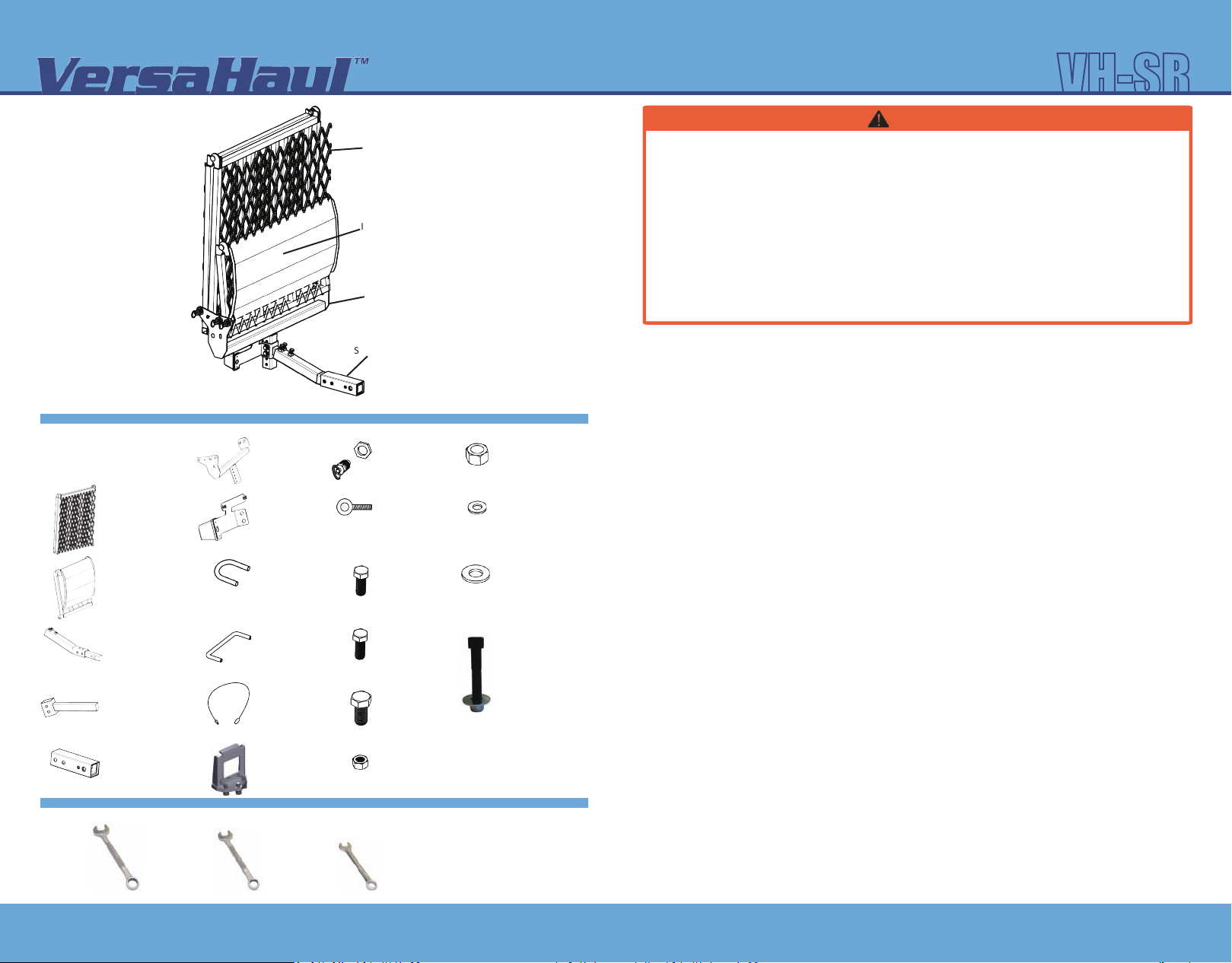
PARTS
NOTE: VersaHaul is aached
with your standard Hitch Pin
(not included).
VH042
(1) Small Inner Ramp
VH046
VH047
(1) Ramp Base
VH034
(1) License Plate
Holder w/Light
VH093
(2) Safety U-Bolt
www.versahaul.com
Outer Ramp
Inner Ramp
Ramp Base
Snger
Toward Vehicle
(3) Pull Pin & Nut
VH300
VH310
(1) Eyebolt(1) Large Outer Ramp
(3) Bolt
3
/8” x 3/4”
VH232
1
/2” Nut
(2)
VH242
5
/16” Washer
(2)
VH222
1
/2” Washer
(2)
VH245
VH-SR
WARNING
1. Read all instrucons for future reference.
2. Follow all warnings and instrucons marked on the
product.
3. Do not stand on the VersaHaul.
4. Do not ride any vehicle while loading onto the
VersaHaul.
5. Always store the VersaHaul in a safe place.
6. Never exceed vehicle tongue weight rangs.
7. Only use VersaHaul with Class 3 or 4 hitch. Most
Class 3 hitches limit the VersaHaul to 500 lbs. total
hauling capacity.
LIMITED WARRANTY
The Limited Warranty on the VersaHaul Carrier.
BNK, INC warrants the carrier and related components. This warranty applies to any part found to be defecve due to
material and/or workmanship when inspected at the factory of BNK, Inc., Winamac, IN. BNK Inc. will, at its opon,
repair or replace defecve parts to the original purchaser at no charge other than transportaon. Sale receipt as
proof of date of purchase is required, which will be returned. BNK, Inc. assumes no liabilty for labor charges made in
performance of this warranty.
The warranty periods are as follows from date of purchase:
CARRIER FOR 1 YEAR, VOID IF: frame is broken or bent due to abuse. example: (underside scraped abusively)
ALL WARRANTIES ARE VOID IF: the carrier has been rented, used under abnormal condions, or subjected to
abuse, misuse, neglect, or improper maintenance.
All warranes should be handled at point of purchase unless other arrangements are made.
BNK, Inc. is not liable for any damage claim or liability cliam, personal or otherwise resulng from operaon of this
carrier in any way. All transportaon charges for items returned for warranty evaluaon and/or replacement are to be
borne by the customer.
8. Improper use, storage or installaon of ramp could
result in death or serious injury.
9. Do not put any VersaHaul on a 5th wheel trailer or
any other kind of trailer.
10. VH-SR carrying capacity is limited to 300 lbs. max.
Your vehicle suspension and hitch may limit the
hauling capacity of the carrier. For more
informaon on vehicles and hauling capacies, visit
www.versahaul.com.
For one (1) year from the date of purchase, BNK, Inc. will repair or replace for the original purchaser, without charge,
any part or parts are manufactured by BNK, Inc. and found, upon examinaon at our factory in Winamac, to be
defecve in materials and/or workmanship.
All transportaon charges on parts submied for replacement under this warranty must be borne by the purchaser.
This warranty does not apply to parts not manufactured by BNK, Inc. Their manufacturer may warrant these items.
This warranty does not apply to any part which has been damaged by accident, alteraon, abuse, improper
adjustment, normal wear, or any other cause beyond our control.
Use of replacement parts other than genuine BNK, Inc. parts may impair the safety of your machine and void this
warranty.
IMPORTANT
THIS WARRANTY IS VOID UNLESS THE PRODUCT REGISTRATION CARD IS FILLED OUT COMPLETELY AND
RETURNED TO THE FACTORY AT WINAMAC, IN. WITHIN TEN (10) DAYS OF PURCHASE.
OUR WARRANTY COVERS OUR PRODUCT FOR ONE YEAR. WE ARE NOT ABLE TO EXCHANGE
USED VERSAHAUL CARRIERS FOR REFUNDS OR NEW CARRIERS.
TOOLS
(1) Angled Snger
VH027
(1) Adjustable Slider
VH035
(1) Snger Cover
VH023B
½" Wrench
(2) Ramp Handle
VH330
(1) Safety Lanyard
(1) An-Tilt
Lock Bracket
VH070
3
/8" Wrench
(2) Bolt
5
/16” x 21/2”
(2) Bolt
1
/2” x 21/2”
VH241
5
/16” Nut
(2)
VH223
5
⁄₁₆" Wrench
(1) Alternave Lock
Bracket Assembly
VH073
Includes:
7
⁄₁₆" x 2 3/4” Bolt
•(1)
VH235
7
•(1)
⁄₁₆" Lock Nut
VH236
7
•(1)
⁄₁₆" Washer
VH237
BNK,Inc. 9341 S. St Rd. 39 Winamac, IN 46996 Problems? Questions? Call us at (888) 818-9915
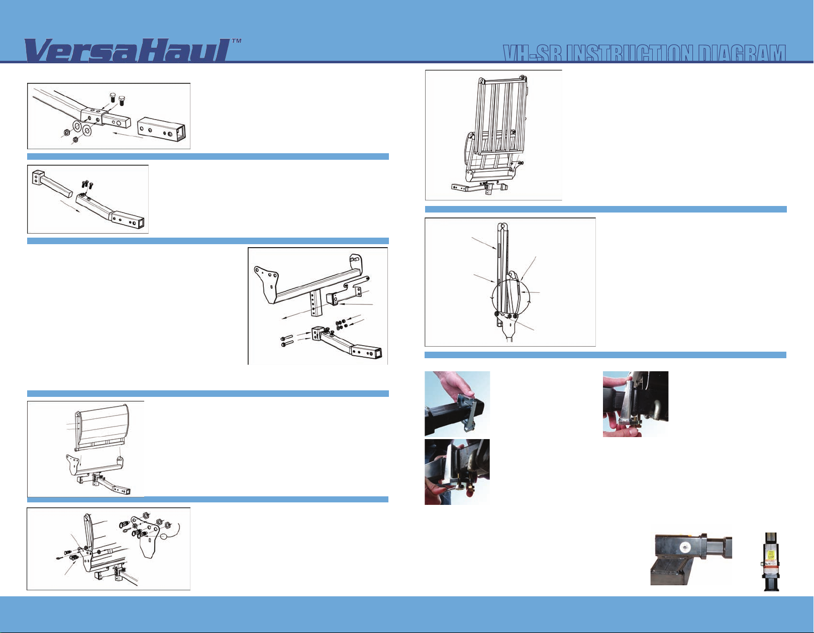
ASSEMBLING YOUR VERSAHAUL
1
/2” Snger Bolt
Angled Snger
Adjustable Slider
1
/2” Nut
1
/2” Washer
3
Lock Bolt
/8” x 3/4” Snger
Snger Cover
Step 2
Insert the adjustable slider into the snger and secure at the
desired length with the three
Make sure all three bolts are secure against the slider.
Step 1
Place the snger cover over the end of the angled
snger and align the holes. Secure the two pieces
together with the two
1
/2” x 2 1/2” bolts, washers,
and nuts.
3
/8” x 3/4” snger lock bolts.
Outer Ramp
mobility scooter safety ramp
VH-SR INSTRUCTION DIAGRAM
Step 6
Safety
Handle
Safety
Loop
2
1
Aach the large outer ramp to the ramp base using the
same method as in Step 5. Bolt on the handle and the
safety loop on the side of the ramp. The expanded metal
mesh ramp surface has been removed for illustrave
clarity.
Angled Snger
Step 3
Insert the ramp base into the adjustable slider and line
up the holes on both pieces. Make sure the ramp base
plate with holes is facing you if the snger is poinng off
to your right. Place the license plate cover over the holes
and secure the three pieces together at the desired
height with the two
5
/16” X 2 1/2” adjustable bolts, nuts,
and washers. License Plate Holder: Push the square
plasc grommets for mounng the license plate through
Ramp Base Plate
with Holes
5
/16” x 2 1/2” Bolt
Ramp Base
5
/16” Washer
5
/16” Nut
License
Plate
Holder
Snger
Light
the square holes in the rounded tab. Pull the wires for
the light through the large hole and fasten the light to
the holder with the screws provided with the light. Make sure the light is facing towards the
license plate.
Step 4
Safety Handle
& Loop
Placement
Inner Ramp
2
Aach the smaller inner ramp on the snger side. The small
ramp must go on first. Slide the round pin through the hook
on the right side of the ramp and lt the ramp unl the le
hook aaches over the le flat pin. Bolt on the handle and
1
the safety loop to the inner ramp.
Step 5
Hole for Eyebolt
Pull Pins and Nuts
Eyebolt
Loop of Safety Lanyard
goes around this pin
Closeup of Ramp
Base Plate
Once in place, screw in the le two pull pins to
lock both ramps in place. On the rightmost pull
Safety
pin, remove the nut and place the lanyard look
Lanyard
around the pin. The loop will have to go over the
threads on the pull pin. Screw the pin in place to
secure the lanyard and fasten all pull pins with
nuts. Screw in eye bolt to secure safety lanyard.
Step 7
Handle
Safety Loop
Safety Loop
Handle
Safety Lanyard
Eyebolt for securing
safety lanyard latch
Run the latch end of the safety lanyard through
the loops and secure to the eye bolt.
ATTACHING YOUR VERSAHAUL
Step 1 Step 2
Mount the three
included An-Tilt Lock Bracket.
Insert bracket to the main tube
as shown.
Step 3
Put the bracket flush against the hitch collar. Tighten the center bolt unl it fits snugly
against the receiver hitch underside. Tighten the two side bolts; then re-ghten the center
bolt. Make sure all bolts are ght enough such than no slack exists between the main tube
and the hitch. Note: Road vibraon may cause bolts to loosen over me. Test by rocking
the carrier from the sides. Minor deformaon is normal on the contact area between the
main tube and the an-lt bracket.
Alternative Instructions
If the An-Tilt Lock Bracket does not fit, use the An-Tilt Hitch Aachment Bolt. The An-Tilt Hitch Aachment
7
Bolt has a
/18” thread size, a 3/8“ Allen Head size, and a 5/8” outer
head size. Slide the Main Tube of the carrier into the hitch receiver.
Secure the Main Tube to the receiver with the An-Tilt Bolt, Washer
and Nut. The Bolt must be inserted into the
hole. Note: Do not put a washer at the bolt head, but rather at the
nut. The bolt head should be recessed into the receiver hole and be
pung pressure on the Main Tube of the Carrier inside the receiver.
3
/8” bolts to the
7
/16” hole, not the 5/8”
Insert main tube into vehicle’s
receiver hitch and install hitch pin
(not included).
Bolt Head Side View
Carrier Main Tube
Hitch
Top View
For more information on your VersaHaul, please visit www.versahaul.com Problems? Questions? Call us at (888) 818-9915
 Loading...