

Page 1

SRM
OPERATIONAL
MANUAL
MADE IN USA
Page 2

Page 3

TABLE OF CONTENTS
Page
FOR THE CLINICIAN ............................................................................................................................2
GENERAL INTRODUCTION .................................................................................................................3
SELECTING EXERCISE TIME .............................................................................................................3
CALORIE BURN RATE .........................................................................................................................3
HEART RATE TRAINING GUIDE .........................................................................................................4
CLIMBING USER’S GUIDE ..................................................................................................................5
STEPPER USER GUIDE ......................................................................................................................5
MODULE DISPLAY ...............................................................................................................................6
SELECTING AN OPPONENT ...............................................................................................................7
SELECTING A LANDMARK ..................................................................................................................7
USING HYDRAULICS TO CONTROL SPEED .....................................................................................7
PROGRAMMING HEART RATE ...........................................................................................................8
VERSACLIMBER SPECIFICATIONS ...................................................................................................8
UNPACKING INSTRUCTIONS .............................................................................................................8
TOOLS AND PARTS .............................................................................................................................9
ASSEMBLY INSTRUCTIONS ....................................................................................................... 10-14
APPLICATIONS FOR SPORTS REHAB ...................................................................................... 15-16
HOW TO SET UP ADJUSTABLE SEAT ....................................................................................... 17-19
STRENGTH INTERVAL TRAINING .............................................................................................. 20-21
MAINTENANCE INSTRUCTIONS ......................................................................................................22
ASSEMBLY FOR HIGH-TRI AND HIGH-FIVE ...................................................................................23
PREVENTATIVE MAINTENANCE SCHEDULE .................................................................................24
WARRANTY/CONTACT INFO ............................................................................................................25
- WARNING NOTICE -
In order to maintain highest safety level of equipment, a regular examination is required for damage
and wear. A visual inspection of connectors, cables, chains, pulleys etc. is required on a regular basis.
Replace defective components immediately and/or keep equipment out of use until repair is made.
*These statements have not been evaluated by the FDA. These products are not intended to diagnose,
treat, or cure any disease. Benefits listed are based on research that may or may not be independent of
Heart Rate Inc. products.
Heart Rate Inc. All Rights Reserved © 2016. Pat NO 5,679,100 & 5,492,515 Proudly Made in USA since 1981.
NOTE
FDA STATEMENT
Page 4

The SportsRehab (SRM) VersaClimber:
An Arsenal of Uses for the Clinician
Sportsmedicine and rehab specialists deal with diverse populations. These segments can range from the
athlete, the cardiac patient, the obese, and the amputee or wheelchair patient. The Rehab VersaClimber is an
exceptional closed chain tool for all of these populations.
REHAB FOR THE ORTHOPEDICALLY IMPAIRED
Three phases of closed chain rehab are available for the orthopedically impaired.
Phase 1 is for patients who need to eliminate one or more extremities from the exercise. The
patient exercises in a non-weight bearing seated position while supporting the stationary lower
injured limb with the leg isolator or not using the limb in the case of an injured upper body
extremity. Seated pushing and pulling with the arms and/or legs in any combination elicits a nonweight bearing conditioning response.
Phase 2 involves all four or any combination of the extremities while the person’s body weight
is partially supported by the seat. Orthopedic loading allows involved or weakened extremities
to be safely exercised either actively by continuous active motion or passively by continuous
passive motion. Partial weight bearing may be elicited in the legs and/or lower back in the
standing position by supporting the upper body with the arms when stepping.
Phase 3 is for patients that can bear full weight in the climbing position. The seat may remain
in place while climbing to partially support body weight or allow for seated rest intervals due
to fatigue.
A great application of the VersaClimber is integration into a full body treatment plan. Injuries
that prevent walking or running do not have to limit climbing. The patient does not have to
counteract impacting, gravitational or mechanically produced forces. Acute and chronic leg,
knee, arm, chest, shoulder and back injuries can be safely exercised on the VersaClimber.
CONTROLLED RANGE OF MOTION (ROM)
ROM can be controlled for upper and lower limbs on one or both sides of the body in two inch increments while
seated, stepping, or climbing. For example, one leg can be free to take a 1 inch through a 20 inch step while the
injured leg is restricted to zero degrees of deflection at the knee and hip joints. Patients with pathology involving
the total immobilization of one or more limbs can be exercised effectively and safely. ROM can be gradually
increased along with weight bearing for applications such as a knee injury post-op all the way through the rehab
process to full functional ROM and weight bearing. For injuries requiring a limited ROM of plantar and dorsiflexion, a locking pin in the foot pedal can be utilized.
VersaClimber features integrated Polar compatible heart rate monitoring providing clinicians the ability to
precisely control exercise and accommodate even the most dysfunctional or de-conditioned patients. Low-level
Work performed is quantified in feet per minute. Hydraulic resistance is selected on the control panel. Step
height and rate are individualized for the patient.
Individuals in wheelchairs, cardiac patients, the obese, diabetics, and those with orthopedic injuries may
not be able to exercise effectively on treadmills, bikes, ellipticals, and steppers. The Rehab VersaClimber
accommodates this entire gamut of the population. No other exercise modality offers such a vast arsenal of
applications along with the ability to precisely prescribe and control exercise for each individual condition. Every
clinic should have at least one SportsRehab SRM VersaClimber.
*These statements have not been evaluated by the FDA. These products are not intended to diagnose, treat, or cure any disease. Benefits listed are based on research that
may or may not be independent of Heart Rate Inc. products.
CONTROLLED WORK INTENSITY
. no i t i sop de t aes eh t n i r ebmi l Cas r eV eh t no es i c r exe nac y t i capac l ano i t cnu f TEM 2 a h t i w s t ne i t ap ca i d r ac
CONCLUSION
Page 2
Page 5

First time users: You might have a tendency to
climb too fast and to take too long a step. Until
users become thoroughly familiar with the Versa
Climber, it is important to take short, slow steps.
microcomputer monitors and displays climbing
performance, heart rate, calories, distance, time
and gives audible instructions and motivational
messages during the exercise. The machine is
oriented at a 75-degree climb angle.
BEFORE EXERCISING ON THE VERSACLIMBER,
READ THIS OPERATION MANUAL THOROUGHLY.
INSTRUCT OTHERS HOW TO USE THE MACHINE IN
ACCORDANCE WITH THE PROCEDURES OUTLINED
IN THIS MANUAL. ADDITIONAL MANUALS ARE
AVAILABLE UPON REQUEST FROM HEART RATE, INC.
BEFORE BEGINNING THIS OR ANY OTHER EXERCISE
PROGRAM, CONSULT YOUR PHYSICIAN. THIS IS
ESPECIALLY IMPORTANT FOR THOSE INDIVIDUALS
OVER THE AGE OF 30 AND THOSE WHO HAVE KNOWN
HEALTH PROBLEMS. HRI ASSUMES NO
RESPONSIBILITY FOR PERSONAL INJURY OR
PROPERTY DAMAGE SUSTAINED BY OR THROUGH
THE USE OF THE VERSACLIMBER
GENERAL INTRODUCTION
The VersaClimber, introduced in 1981, was the
first climbing exercise machine on the market;
and to this day remains the leader as a true total
body conditioning unit. This full body climbing
exercise machine provides an alternating arm
and leg action against gravity with variable force,
stroke length and speed. All the major muscles
of the arms, chest, shoulders, back, hips, but and
legs are used while climbing. The VersaClimber
has been proven worldwide and is a widely
accepted total body exerciser that is used by
health clubs, sports medicine facilities, military,
fire departments, corporate gyms and wherever
groups of people gather to exercise.
To climb, the person stands in a vertically erect
position with both feet level on pedals while
grasping two handgrips set at about shoulder
height. To initiate climbing motion, step down on
one foot pedal while pushing up on the hand grip.
When the foot and hand move vertically downward,
the other foot and hand move vertically upward
and then alternate synchronously. A cyclic action
of the arms and legs
is performed that simulates
motion of climbing an endless ladder for any
selected step height, time, rate and distance. A
NOTE:
Don’ t Climb Too Fast. Beginners
Should Take a 4 -6 inch step at a Gentle Pace
First time users of the VersaClimber have a
tendency to climb too fast and to take too long a
step. Until users become thoroughly familiar with
the VersaClimber, it is important to take short, slow
steps. To maintain a shock and trauma free motion,
it is mandatory not to “bottom out” or impact the
pedals at the end of each stroke.
SELECTING EXERCISE TIME
If you are not already warmed up, a warm up period
of at least 5 to 10 minutes should be included in
each VersaClimber workout. Taking a short step at
a slow climbing speed during the warm up period is
the key to a great workout. The first time user can
easily climb for 15 to 20 minutes by including a slow
5 minute warm up and a 3 to 5 minute cool down
period. With repetitive use it is possible to build up
to longer climbs at higher speeds.
Many individuals enjoy 60 minutes or more of
uninterrupted climbing. After each workout, note
exercise time, climbing speed and height climbed
for establishing a goal for
future sessions. Use heart
rate and perceived exertion to determine if you are at
a comfortable exercise level. Remember that work
intensity and calorie burn rate is based on climbing
speed. If the exercise is too hard, slow down.
CALORIE BURN RATE
Full body climbing ranks highest in calories
burned even though climbing speed is slower
than other activities. First time users often try to
maintain the speed they use in other activities and
tend to over exert themselves. It is important to
remember that because VersaClimbing is a total
body climb against gravity, it is not necessary to
climb at a high rate of speed, as shown on the
next page.
Page 3
Page 6

T R A I N I N G
Z O N E
Maximum Heart Rate
85% of Maximum
AGE
45
40
35
30 25 20
HOW TO FIND YOUR
85% of Maximum Heart Rate
TARGET HEART RATE?
Heart rate is the best indicator of exercise intensity. Use your heart rate and level of perceived
exertion (how you feel) as a guide to determine if you have selected the proper “LEVEL OF
CONDITIONING”. The following HEART RATE TRAINING ZONE CHART may be used to
assist you in selecting your appropriate heart rate training zone.
HEART RATE TRAINING GUIDE
1. Find your age at the bottom of the chart.
2. Beginners follow the column to 70% of your
maximum heart rate.
3. Advanced follow the column to 85% of your
maximum heart rate.
4. Exercise at your appropriate heart rate.
200
195
100%
85%
70%
155
132
109
160
136
112
165
140
116
170
145
119
175
149
123
180
153
126
190
185
166
162
157
137
133
130
170
140
NOTE:
TO MAINTAIN TRAUMA FREE MOTION, IT IS MANDATORY THAT YOU DO NOT, UNDER ANY
CIRCUMSTANCES, “BOTTOM OUT” AT THE END OF EACH STROKE. ALSO, DO NOT HIT THE
STEP HEIGHT LIMITERS WHEN THEY ARE IN USE.
*These statements have not been evaluated by the FDA. These products are not intended to diagnose, treat, or cure any disease. Benefits listed are based on research that
may or may not be independent of Heart Rate Inc. products.
Page 4
Page 7

CALORIES ACTIVITY
(For a 15 0 lb person)
SPEED Per Hour
Walking 3.0 mph 228
Bicycling 9.4 mph 384
Swimming 2.0 mph 486
Running 7.5 mph 792
Stepping 1.9 mph 864
Climbing 0.9 mph 972
STEPPING USER GUIDE
USE THE VERSACLIMBER AS A STEPPING
MACHINE OR A CLIMBING MACHINE.
The side handrails not only provide support while
getting on and off the VersaClimber but they
offer the option of Stair Stepping. By holding the
handrails to the side of the body and stepping with
the legs only, the gluts, quads, hamstrings, calves
and shins can achieve a complete lower body
aerobic and strength exercise.
Burned
height. Adjust handles if necessary by depressing
the pin at the end of the handgrip. Remove
the handgrip and reinsert it fully into another
position and release the pin.
NOTE:
WHEN GRASPING THE HAND RAILS OR
HAND GRIPS, KEEP FINGERS AND THUMBS
ON THE FOAM PADDING OF THE HANDRAILS
OR RUBBER GRIPS OF THE HANDLES. DO
NOT GRASP OR EXTEND ANY PORTION OF
THE HAND BEYOND THE FLANGES OF THE
MOVING HAND GRIPS. DO
NOT HOLD ONTO
THE VERTICAL POST.
Push quick start on the module and follow verbal
user instructions. Time, Rate, Distance, Step
Height and other information is displayed. See
page 6 for detailed display functions including
Heart Rate and Calories.
The SRM provides a step height of 1-20 inches.
By shifting the hands from the stationary
handrails to the moving handgrips, the machine
automatically converts from a stepping machine
into a total body-climbing machine or back to a
stepping machine simply by changing hand position.
CLIMBING USER GUIDE
Hold handrails for support and step up on the
pedals until both feet are level. With both feet at
the same level, position handgrips at about chin
Begin climbing by taking a step stroke length of
approximately 5 inches at a speed of 20 feet per
minute for approximately 5 minutes. After 5
minutes the step height and climbing speed can
be gradually increased if desired.
To maintain a shock and trauma free motion, it
is strongly suggested that you do not, under any
circumstances, “bottom out” at the end of each
stroke.
Page 5
Page 8

IMMEDIATELY DISCONTINUE THIS OR ANY
EXERCISE IF THERE IS ANY DISCOMFORT,
SHORTNESS OF BREATH OR DIZZINESS.
MODULE DISPLAY
6. LOCK SELECTION
Press this button to enter user selected values into
the computer.
7. YELLOW LOCK SELECTION ARROWS
These buttons are used to raise or lower the
number in the display.
The control module consists of 17 push buttons with
associated back lit text descriptors, a 32 character
LCD display and a voice message system which
provides verbal instructions for new users. The text
descriptors are back lit descriptions of what function
or activity is currently associated to each button.
Here is a brief discussion of the functions provided
8. “Upper” Left SELECT button.
Press this button to switch the display between
ELAPSED TIME and TIME REMAINING in the
workout period. The remaining time display stops
at zero while the elapsed time continues counting
up to 99 hours:59 minutes:59 seconds.
by each instruction.
9. “Center” SELECT button.
1. QUICK START
When pressed, it clears the display of any previous
Press this button to switch between TOTAL
CALORIES and CALORIES PER HOUR.
information and verbally guides the first time user
through a 15 minute workout.
10. “Upper” right SELECT button.
If the machine is not running in one of the specialty
2. SELECT AN OPPONENT
Press this button repeatedly to select one of six
virtual opponents to race against. This a speed race.
modes (Opponent, Landmark, Heart Rate Control
or Race Your Neighbor) this button has no function
as both STROKE LENGTH and DISTANCE PER
MINUTE will be displayed continuously. When any
3. SELECT A LANDMARK
Press this button repeatedly to select one of six
Landmark goals. This is a distance challenge that
of the specialty modes are selected, this button will
switch the display between STROKE LENGTH and
DISTANCE PER MINUTE
you climb at your own desired speed.
11. “Lower left” SELECT button. Press this button
4. ENTER WEIGHT
to switch between metric and imperial display units.
Press this button to enter your weight which is used
to calculate caloric burn rate. Use the yellow LOCK
SELECTION arrows to raise or lower the number
in the display until it matches your weight within
plus or minus five pounds (or two kilograms). Then
press the LOCK SELECTION button to enter your
12. “Lower right” SELECT button.
Press this button to switch between OPPONENT’S
TOTAL DISTANCE and OPPONENT’S DISTANCE
PER MINUTE. This button is only active when
virtual opponent mode is selected.
weight into the computer.
13. VOLUME CONTROL
5. ENTER TIME
Press this button to increase or decrease the
Press this button to sequentially play each of the
voice instructions.
default workout period of 15 minutes. Use the
yellow LOCK SELECTION arrows to raise or lower
the number in the display until the desired time
is displayed. Then press the LOCK SELECTION
14. YELLOW VOLUME CONTROL ARROWS
Use these buttons to raise or lower the voice
message volume level.
button to enter your time into the computer.
*These statements have not been evaluated by the FDA. These products are not intended to diagnose, treat, or cure any disease. Benefits listed are based on research that
may or may not be independent of Heart Rate Inc. products.
Page 6
Page 9

15. SPECIALTY MODES
Press this button to select HEART RATE
CONTROL MODE or RACE YOUR NEIGHBOR
(an optional feature that will be available in the
future).
SELECTING EXERCISE TIME
If you are not already warmed up, a warm up
period of at least 5 to 10 minutes should be
included in each VersaClimber workout. Taking
a short step at a slow climbing speed during the
warm up period is the key to a great workout. The
first time user can easily climb for 15 to 20 minutes
by including a slow 5 minute warm up and a 3 to
5 minute cool down period. With repetitive use it
is possible to build up to longer climbs at higher
speeds.
Many individuals enjoy 60 minutes or more of
uninterrupted climbing. After each workout, note
exercise time, climbing speed and height climbed
for establishing a goal for future sessions. Use
heart rate and perceived exertion to determine
if you are at a comfortable exercise level.
Remember that work intensity and calorie burn
rate is based on climbing speed. If the exercise
is too hard, slow down.
LEVEL OF CONDITIONING
CLIMBING FOR 15 MINUTES
SPEED DISTANCE
FEET/MIN FEET
1. BEGINNER 35 525
2. INTERMEDIATE 65 975
3. COMPETITOR 95 1425
4. CHAMPION 120 1800
5. ELIMINATOR 160 2400
6. OLYMPIAN 200 3000
USING HYDRAULICS TO CONTROL SPEED
Beginners and individuals who are deconditioned
may use the hydraulics to control their climbing
speed, rather than working against the resistance.
The hydraulic control knob is located at the bottom
of the control console. Clockwise rotation of the
control knob, (to the
right), slows the rate
of motion (easier).
Counterclockwise
rotation of the
control knob, (to
the left), increases
the rate of motion
(harder). The rate
of motion, (slower/
faster), may be
changed without
stopping any time during exercise. Start with
the speed control knob fully rotated clockwise
and gradually increase the climb rate to the
desired speed by turning the control knob in the
counterclockwise direction. Climb at the speed
set by the resistance.
Climbing uses many more muscles than jogging,
pedaling , stepping or elliptical exercises and is
therefore performed at a slower cyclic rate and
speed. Speed in “Feet Per Minute” is an accurate
guide for the amount of work being done.
A reasonable starting rate for a person in good
condition would be about 80 to 110 feet per
minute. After a few minutes of exercise, heart rate
should be checked and the climb rate increased or
decreased appropriately to bring the user to their
target heart rate zone.
SELECTING A LANDMARK
There are 6 landmarks from 554 feet to 9731 feet
high to choose from.
SELECTING AN OPPONENT
The opponent you select will climb at the average
speed listed above. If you are not able to keep
up with the opponent you selected, slow down
and finish the 15 minute race. Select a slower
opponent for the next workout.
LANDMARK HEIGHT
1. Washington Monument 554
2. Eiffel Tower 984
3. Moscow Tower 1,762
4. El Capitan 3,297
5. Vesuvius 3,900
6. Mount Olympus 9,731
Page 7
Page 10

Select a landmark based on the total distance
climbed during previous workouts.
EQUIPMENT: (single unit)
A. Vertical mainframe with control console attached
VERSACLIMBER SPECIFICATIONS
PHYSICAL SIZE
Height 7 feet, 10 inches
Footprint 43 inches x 50 inches
Weight 165 pounds (70 kg)
FUNCTIONAL FEATURES
Pedal Step Height 0 to 20”
Arm Stroke Length 0 to 20”
Overall Climb Rate
Ability Of Person Climbing
Hydraulic Climb Rate Control 6-107 m/min
Hydraulic Force Control 0 To 500 lbs
Climb Angle 75 Degrees
Vertical Lift Factor (% slope) 96.6 Percent
USER ACCOMMODATIONS
Level of Physical Fitness Novice To Elite
Climber’s Height 4’ 2” to 6’ 7”
Climber’s Weight 65 lbs to 350 lbs
Age and Sex Any
MODULE FUNCTIONS
Exercise Time 0 to 99.9 Hours
Exercise Rate 0 to 351 FT/min
Exercise Distance 0 to 10,000 FT
Step Height 0 to 20 inches
Race against opponent 35 to 200 FT/min
Climb a Landmark (Distance) 554 to 9731FT
Heart Rate Display 30 to 235 (BPM)
Calorie burn rate 0-2000
Display Units Imperial and Metric
Audio Volume Control
Power Transformer 110 Volt AC
B. Two foot pedals. Four hex head bolts, 3/8” x 1
1/2” long
C. Two quick disconnect handles
D. (OPTIONAL) One pair of handle extenders, one
pair of hand rail spacer, four screws, 1/4” x 4” long
E. One front curved tubing base
F. One back straight tubing base. Two hex head
bolts 3/8” x 3 3/4” long. Two 3/8” lock nuts
G. One (small) brace, post to back base. Two 3/8”
lock nuts. One (long) brace with adjustable settings.
One 2.5” bolt, two washers, one 3/8” nut, isolator
brace, and four isolator shafts
H. Two side handrails. One 3.2” hand rail spacer.
Three hex head bolts 3/8 x 4.25” long for side hand
rails and three 3/8” lock nuts
I. One plastic Pump Cover. Four black Phillips pan
head screws, No. 6 x 3/8” long.
J. One transformer. 110 volt AC Adapter
K. One set of run handles
L. One polar strap
UNPACKING INSTRUCTIONS
1. Remove the shipping container’s top cover.
Then remove the wooden cross support that holds
the mainframe down and the two bolts at the end
of the container with two 9/16” wrenches. Using two
people, carefully remove the vertical mainframe
from the container and lay the machine on the floor
with pump supported on the wooden cross support
(see photo on page 11). Avoid lifting the machine
by or setting the machine on any potion of the black
plastic housing or plastic oil accumulator.
2. The following items are packaged in the container.
Page 8
Page 11

TOOLS REQUIRED FOR ASSEMBLY
OF A SINGLE UNIT:
A. One Phillips screw driver
B. Two 9/16” wrenches
C. 3/4” open wrench or crescent wrench
D. Two able bodied persons are required
for assembly
PARTS FOR ASSEMBLY
OF A SINGLE UNIT:
Lower Limb Isolator Shafts
Lower Limb Isolator Brace
Straight
Handles
Clevis Pins (locking Pedal)
Pedal Assembly
Running Handles
H1 Polar Chest Strap
Leg Stabilizer Tie
Adjustable Seat
Page 9
Page 12
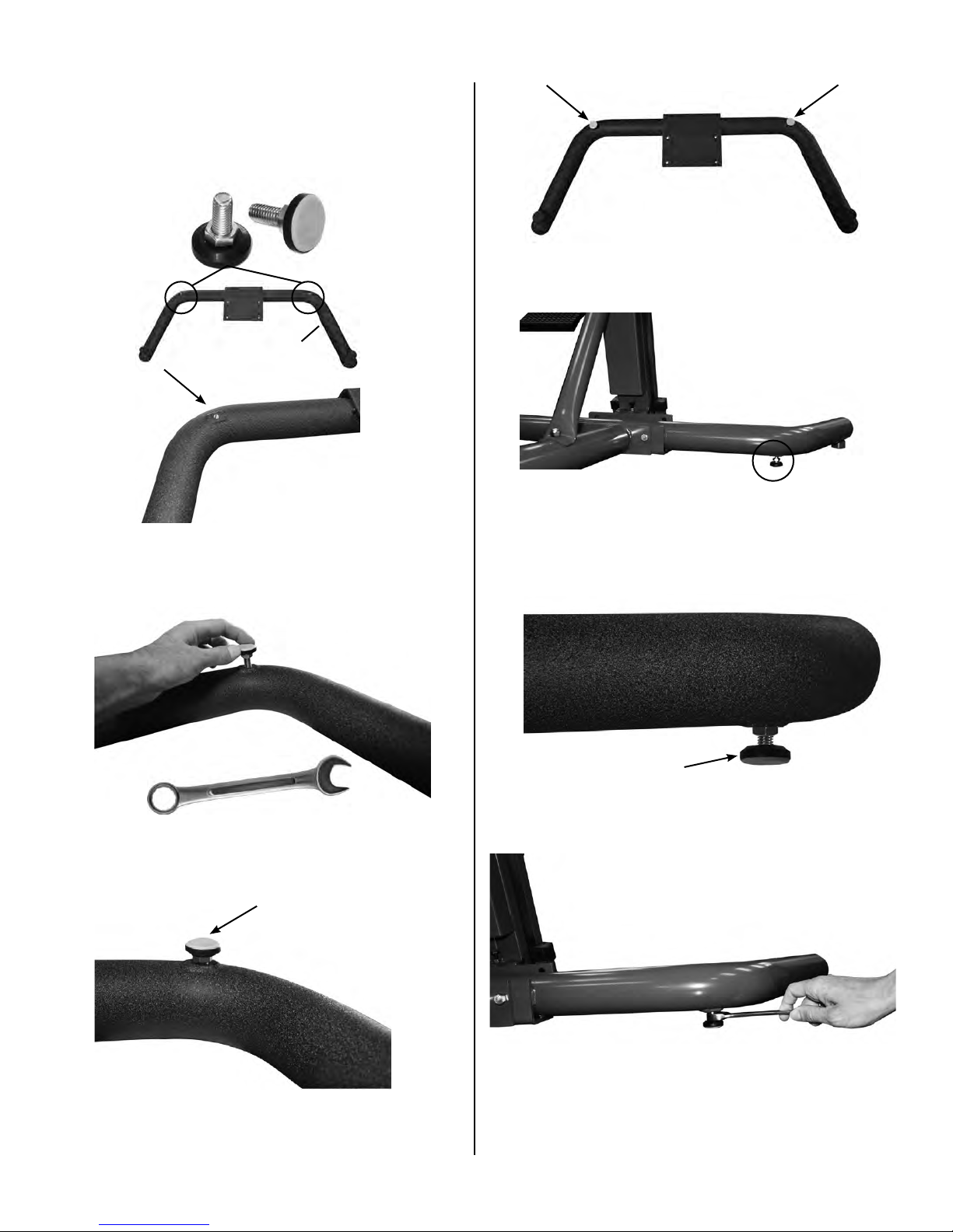
FRONT U BASE STABILIZER INSTRUCTIONS
(When attaching the front curved floor base)
Two Stabilizer Knobs for U Base.
Front
Locate the threaded inserts on the underside of
the front U base at the sections that curve.
Front base with stabilizer knobs attached.
Front base with stabilizer attached, when your
VersaClimber is completely assembled and
placed where it will be used, you can now adjust
the stabilizer knobs down.
Required Tool: 9/16” Wrench
Screw in stabilizers in both threaded holes on
front base.
Make sure stabilizers
are screwed all the way
down before assembling
VersaClimber.
Make sure to screw the stabilizer all the way
down into the threaded hole, as seen above.
Page 10
Screw down knobs until pads are touching the
floor or just resting on floor.
Once both knobs are set into position, spin the
hex nut up until secured at the bottom of the front
base tube then tighten firmly with a 9/16” open
wrench, to lock stabilizer in place.
Page 13
ASSEMBLY INSTRUCTIONS
– WARNING NOTICE –
In order to maintain highest safety level of equipment, a regular examination is required for
damage and wear. A visual inspection of connectors, cables, chains, pulleys etc. is required on
a regular basis.
NOTE:
Replace defective components immediately and / or keep equipment out of
use until repair is made.
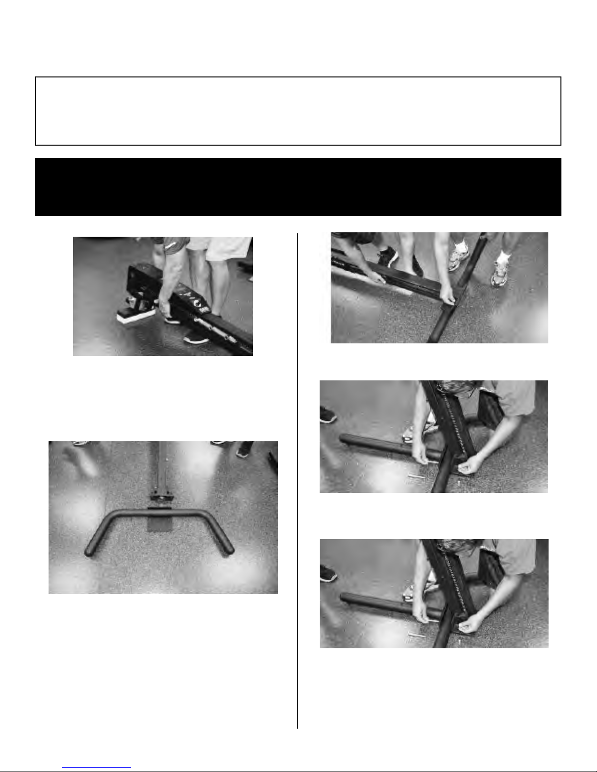
Protect the oil reservoir and the black plastic
computer housing by supporting the Versa
Climber hydraulic pump on wooden cross support
from wooden crate.
Attach the front curved tubular floor brace to the
post. Using four hex head bolts, 3/8” x 5/8” long
screw down until firmly tight.
Screw in (4) self tightening base bolts.
Using two people lift and hold VersaClimber in
upright position.
Attach back tubular floor brace to post with two
hex head bolts, 3/8”x 3 3/4” long. (2) 3/8” lock nuts.
DO NOT TIGHTEN FULLY AT THIS TIME. After
tubular brace is in place, TIGHTEN the two 3 3/4”
long base bolts with two 9/16” wrenches.
Page 11
Page 14

Then go back and TIGHTEN FULLY the TOP
lock nut on the tubular brace with 9/16” wrench.
Next, tighten the BOTTOM lock nut on the back
brace to complete post assembly with 9/16” wrench.
Side Hand Rails
Attach side handrails with (3) hex head bolts
4.25“ long and (3) 3/8” lock nuts.
Insert 3.2” long spacer and fully tighten ALL
three bolts and nuts with two 9/16” wrenches.
Place the bottom of the leg isolator under the
base as shown.
Join left and right hand rails.
Loosely attach two 3/8” lock nuts nearest to the
inside center of machine.
Next place the top of the leg isolator in the
bracket as shown above and secure with 3/8 nut,
washers and 2.5” bolt with two 9/16” wrenches.
Place leg isolator brace into position.
Page 12
Page 15

Slide isolator tie under back base as shown
in picture.
Apply 3/8-16 x 2 ½” hex head bolt through post,
Apply lock nut and tighten with 2 9/16” wrench.
Attach foot pedals with “ L” pointing up, using (2)
3/8” x 1 1/2” long hex head bolts.
Securely TIGHTEN.
.e m ar f nia m eht fo edis rehto eht tuo dna ,ecarb
Securely TIGHTEN foot pedals with 9/16” wrench.
Thread isolator shaft into isolator brace, screwing
in clockwise. Make sure isolator shaft sits evenly
on both sides of the brace.
With a 3/4” wrench, tighten on the pedal shaft.
Pin in foot pedals.
Page 13
Page 16

Install straight handgrips by depressing pin
with thumb and insert.
Install running handgrips by depressing pin
with thumb and insert.
Apply seat bracket to post in desired position.
Insert pull pin through frame and seat bracket.
– WARNING NOTICE –
In order to maintain highest safety level of equipment, a regular examination is required for
damage and wear. A visual inspection of connectors, cables, chains, pulleys etc. is required on
a regular basis.
Replace defective components immediately and / or keep equipment out of
NOTE:
use until repair is made.
Page 14
Page 17

APPLICATIONS FOR
THE SPORT REHAB VERSACLIMBER
NEW EXERCISE MODALITY FOR REHABILITATION AND CONDITIONING
The Sport Rehab Model (SRM) VersaClimber® is a total body, closed chain, rehabilitation exercise machine. It
utilizes one of the most natural and intensity selective muscular activities to which the body can be subjected.
Total body vertical climbing exercise and rehabilitation routines have been developed to provide a continuous
arm and leg action in a seated or standing position, using a wide selection of stroke lengths, stroke rates, and
resistance levels.
PHASE 1 PHASE 2
PHASE 3
NON WEIGHT BEARING, PARTIAL WEIGHT BEARING AND
FULL WEIGHT BEARING ACTIVITY PROVIDES 3 LEVELS OF REHABILITATION FOR THE
ORTHOPEDICALLY IMPAIRED
For the orthopedic impaired patient or athlete, three levels of closed chain VersaClimber rehabilitation are
available for use during all phases of patient rehab. The three levels consist of non-weight bearing, partial weight
bearing and full weight bearing exercises. Phase 1 is for patients who need to eliminate one or more extremities
from the exercise to be performed. The patient exercises in a non-weight bearing seated
position, while supporting the stationary lower injured limb with the leg isolator, or not
using the limb in the case of an upper body extremity. While seated, pushing and pulling
with the arms and / or legs in any combination elicits a non-weight bearing conditioning
response to exercise. Phase 2 allows a partial weight bearing activity by also utilizing the
seat. Exercise at this level involves all four or any combination of the extremities while
the person’s body weight is partially supported by the seat. The reduced orthopedic
loading allows for involved or weakened extremities to be safely exercised either actively
by Continuous Active Motion (CAM) or passively by Continuous Passive Motion (CPM).
Partial weight bearing may be elicited in the legs and/or lower back in the standing
position by supporting the upper body with the arms when stepping. Phase 3 is for patients that can bear full
weight in the stepping or climbing position. The seat may remain in place while stepping or climbing to partially
support body weight or to allow for seated rest intervals for fatigued patients.
One of the greatest areas of orthopedic application of the VersaClimber arises when it is integrated into a full
body treatment plan. Leg and extremity injuries that prevent walking or running do not have to limit climbing.
The patient does not have to counteract impacting, gravitational or mechanically produced forces. All continuous active and passive movements are smooth, impact free, rhythmic and symmetrical thereby decreasing the
incidence of repeated assault to the affected limb or extremities via orthopedic overload. Acute and chronic
leg, knee, arm, chest, shoulder and back injuries can be safely exercised on the SRM VersaClimber without
risk of exacerbation of the injury site.
*These statements have not been evaluated by the FDA. These products are not intended to diagnose, treat, or cure any disease. Benefits listed are based on research that
may or may not be independet of Heart Rate Inc. products.
Page 15
Page 18

AMBULATORY PATIENTS CAN CLIMB
By utilizing the lower limb isolator, patients with pathology involving the total immobilization of one or
more limbs can be exercised at pre-injury levels effectively and safely. Exercise on the VersaClimber
is recommended for any injury that requires a zero or controlled range of flexion of the hip, knee or
ankle joints, or the controlled contraction of any muscle or stretching of any ligament during flexion
of the hip, knee, or ankle. This is facilitated through the use of orthopedic travel limiters built into the
VersaClimber at two inch increments to control the angle of deflection on one or both lower extremities.
By placing the heal of the injured leg on the foot pedal, it is possible to climb normally without aggravation
of the toe, ball of foot, ankle, achilles or calf injuries. As a result, those patients who traditionally were
unable to walk, run or exercise as a part of the rehabilitative regimen, can now vigorously maintain
muscular and cardiovascular fitness, increase functional capacity and overall strength, thus facilitating
a rapid return to activity or sport.
UPPER BODY INJURIES
The arms, chest, shoulders and back can be totally or partially immobilized while pedaling, stepping
or climbing by placing one or both hands on the stationary hand rails. If upper body limb motion is
desirable without active muscle contraction, the injured arm can be placed on the moving hand grip
and subjected to CPM. A full range of CAM can be achieved with the remaining healthy limbs even if
the upper body injury requires complete removal from the activity.
CONTROLLED RANGE OF MOTION
The range of motion can be controlled for upper and lower limbs, on one or both sides of the body,
while seated, stepping or climbing. The range of motion limiters built into the VersaClimber, are
adjustable in 2 inch increments of motion. This provides a full range of angles of deflection of the knee
and hip joint from zero degrees to the maximum deflection attained at a 20 inch step. To effectively
exercise a patient on the VersaClimber utilizing the limiters, place the foot of the injured leg on the
bottom or lower pedal. Then place the uninjured foot on the higher pedal. Have the patient step up onto
the VersaClimber, grasping the stationary hand rails for support. When the feet are level, adjust the
moving hand grips to chin height. Then set the range of motion limiters to zero inches of motion, for no
deflection of the injured leg, by screwing the limiter into the appropriate hole. The patient is now ready
to climb. One leg will be free to take a 1 inch through a 20 inch step as desired, while the injured leg is
restricted to zero degrees of deflection at the knee and hip joint. Although the afflicted limb is moving
up and down, it is not subjected to any trauma, muscle contraction or exacerbation. The arms and
uninjured leg are being utilized in an alternating push-pull motion that is specific to the VersaClimber,
thus facilitating balanced concentric/eccentric contractions to the anterior and posterior musculature.
Exercise at relatively slow repetition rates can illicit low to maximal heart rates and a strengthening of
major muscle groups in the trunk and the three healthy flexing extremities.
Similarly, the range of motion of the shoulder and elbow joint can be totally isolated or controlled in 2
inch increments of motion with the range of motion limiters.
For injuries requiring a limited range of plantar and dorsi-flexion, a locking pin in the foot pedal limits
the range of motion of the ankle to 15
full flexion of the ankle.
*These statements have not been evaluated by the FDA. These products are not intended to diagnose, treat, or cure any disease. Benefits listed are based on research that
may or may not be independent of Heart Rate Inc. products.
o
while pedaling, stepping or climbing. Removal of the pin allows
Page 16
Page 19

Seat set up height depends on preferred ROM of the involved joints to be performed.
SETTING
Mounting seat bracket assembly to post.
Placing pull pin and connecting seat bracket
assembly to post. Choose a seat height for appropriate non-involved limb rom. Average starting
point is #4 & #5 on bracket.
UP SEAT AND LOWER LIMB ISOLATOR
Patient is seated and safely on climber, foot is
placed into adjustable leg isolator shaft and
safely secured with velcro on strap.
Patient is seated and holding the hand rails.
With adjustable wrench, position the isolator shaft
to comfortably accommodate one or both feet.
Practitioner locates the correct position for isolated patient involved leg lenght.
Patient is in seated
position with leg in
isolator. Patient is doing
a lower body workout
with hands on hand rail
assembly.
Patient is seated and safely on climber,
foot is placed, isolated and supported.
Full weight bearing.
Patient is up right
in climbing position
with seat bracket
assembly for
support if needed.
Page 17
Page 20

WORK INTENSITY IS CONTROLLED USING
HEART RATE MONITORING DURING EXERCISE
The VersaClimber features an integrated Polar compatible heart rate monitoring system. This
computerized biofeedback heart rate control allows clinicians to accommodate even the most
dysfunctional and or de-conditioned patients. According to the American College of Sports Medicine
standard conversion of VO2 max., low level cardiac patients with a 2 MET level functional capacity can
begin exercising on the VersaClimber by pedaling in the seated position.
Obese patients and others such as diabetics may not be able to perform some of the simplest,
common exercises. Others may not be able to exercise on bikes, treadmills, steppers, etc. because of
body weight, orthopedic or girth restrictions. [Heart Rate Monitor] option allows a variety of patients to
exercise on the VersaClimber at their appropriate, prudent target heart rate which is programmed into
the computer by utilizing the heart rate control mode. This mode of operation will monitor and modify
the workout intensity at 30 second intervals, to keep the heart rate at predetermined levels.
SELECTABLE RANGE OF MOTION, STEP RATES
AND RESISTANCE TO MOTION
For the average population, the step height and step rate is determined by the person climbing. The
hydraulic resistance to motion of the arms and the legs is selected on the control panel. By shifting
body weight from one leg to the other, a step height and step rate can be selected that suits the fitness
level of the person climbing. Step heights can be selected simply by stepping at any height desired.
The step rate can also be easily selected by stepping fast or stepping at a decreased rate. Rates can
be as slow as 1 step in 3 seconds, up to as fast as the person is capable of moving, without machine
restrictions. Because of the wide range of controlled flexion and extension of the extremities, the
VersaClimber can be used effectively at any level of physical fitness from sedentary de-conditioned
cardiac patients to elite world class athletes.
REHABILITATION OF PHYSICALLY IMPAIRED
PATIENTS ON THE VERSACLIMBER
SEATED POSITION ON THE VERSACLIMBER PROVIDES CONTROLLED LEG EXERCISE FOR
SPINAL CORD INJURED, STROKE, AND NEUROLOGICALLY IMPAIRED PATIENTS.
The addition of a new padded seat to the VersaClimber allows accessibility by spinal cord injured
patients/athletes, cardiac, neurologically impaired, and amputees. The seat affixed to the VersaClimber
frame is vertically and horizontally adjustable for maximum comfort. The addition of the seat will not
prevent or hinder normal total body climbing movement, nor detract from any of the program options
available on the VersaClimber. The adjustable seat is an important tool for those clinics, hospitals,
physical therapy centers, or gyms requiring more dynamic full body exercise for their disabled or low
functioning patients.
*These statements have not been evaluated by the FDA. These products are not intended to diagnose, treat, or cure any disease. Benefits listed are based on research that
may or may not be independent of Heart Rate Inc. products.
Page 18
Page 21
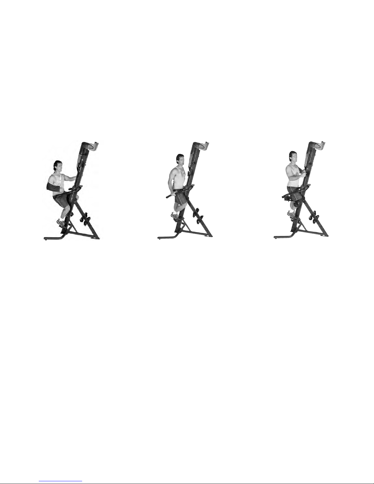
SEATED POSITION ON THE VERSACLIMBER ALLOWS PATIENTS TO MOVE THEIR
LEGS BY PUSHING OR PULLING WITH THEIR ARMS, MOVE THEIR ARMS BY PUSHING
OR PULLING WITH THEIR LEGS OR ANY COMBINATION IN BETWEEN.
Amputees and Spinal Cord injured patients may exercise by using the seat to support either their entire body
weight or any portion that they cannot support with their legs. While seated, pushing and pulling with the
arms causes a continuous passive motion (CPM). Those patients with some lower extremity capability can
also push or pull with their legs to the extent that the injury allows. Range of motion travel stops are built into
all orthopedic models. The travel stops limit the range of motion on one or both sides of the body in 2 inch
increments. Patients with braces, casts, or limitations of body movement can use the limit stops under normal
clinical supervision. They can exercise in a safe non-traumatic seated or standing posture without many of the
contraindications inherent with traditional exercise modalities.
PHASE 1 PHASE 2 PHASE 3
CARDIAC, SPINAL CORD INJURY, AND DECONDITIONED PATIENTS CAN EXERCISE
SAFELY USING ARMS AND LEGS AT LOW INTENSITY.
The seat, along with the Heart Rate Control (HRC)option presents the clinician with a variety of applications
to accommodate even the most disabled or dysfunctional patient. Wheelchair patients that are capable of
sitting erect in their chair and use their arms effectively, are capable with supervision, of exercising on the
VersaClimber. Utilizing non weight bearing, seated upright posture, the patient is capable of facilitating a more
efficient balanced workout utilizing the cross crawl or asynchronous movement available on the VersaClimber.
The patient can control the CPM of injured limbs by the controlled active motion (CAM) of their healthy limbs.
The supportive rails will allow some patients with transfer difficulties the ability to move safely up and onto the
VersaClimber while others will need assistance. The use of the seat will enable deconditioned cardiac patients
(phase II, and III) the ability to exercise arms only, legs only, or combinations of both without exceeding the
appropriate heart rate range. The HRC option allows the patient to exercise in the appropriate prudent target
heart rate which is programmed into the VersaClimber. This mode of operation will monitor and modify the
workout rate in feet per minute, at 30 second intervals to adjust to changes in heart rate. The clinician can use
the new seat, HRC option, and travel stops for a wide variety of patients.
*These statements have not been evaluated by the FDA. These products are not intended to diagnose, treat, or cure any disease. Benefits listed are based on research that
may or may not be independent of Heart Rate Inc. products.
Page 19
Page 22

– WARNING NOTICE –
In order to maintain highest safety level of equipment, a regular examination is required for
damage and wear. A visual inspection of connectors, cables, chains, pulleys etc. is required on
a regular basis.
NOTE:
Replace defective components immediately
and / or keep equipment out of use until
repair is made.
STRENGTH INTERVAL TRAINING
Strength intervals are achieved in a similar manner
to aerobic interval training, except the intervals
are performed at a slow rate of motion. First, turn
the hydraulic control knob located at the bottom
of the console in the clockwise direction, to
approximately 75% of the user’s capability. Begin
climbing, exerting a maximum effort by pushing
and pulling with arms and legs in the upward
and downward direction for 5 to 10 seconds or
until muscles are almost fatigued and anaerobic
threshold is met (not to exceed 85% of your
predicted maximal heart rate). Be sure to use the
foot straps to maximize the vertical lift. Hands
may be in the forward or reverse grip position
depending on the desired muscle groups to be
worked. Recover from the interval by setting the
hydraulic control to a minimum (counter-clockwise
direction) and taking short, slow, 2 to 4 inch
strokes until breathing is controlled and muscles
have recovered. As previously mentioned, as
you become better conditioned, the rest period
between each interval will become shorter.
you walk or run, it is common sense to stop walking
or stop running. If the injury hurts while climbing,
do it easier or do it slower. If it continues to hurt...
stop! Consult with your doctor about any injury
prior to engaging in an exercise program. Some
leg, knee, arm, chest, shoulder and back injuries
can be safely exercised on the VersaClimber
by limiting the range of motion or isolating the
motion of the injured body part on one or both
sides of the body. The smooth, rhythmic, impact
free motion will decrease the likeliness of further
assault to the injured limb while maintaining or
increasing cardiovascular and muscular fitness.
The VersaClimber eliminates all pounding trauma
and provides biofeedback information to the user
to monitor step heights and step rates. It is ideal
for controlled upper and lower body activity for
fitness maintenance during the recovery phase
of minor injuries.
LEG INJURIES
The VersaClimber eliminates pounding and
jarring of the joints and can therefore be used to
exercise such injuries as hamstring pulls, knee
injuries, shin splints, achilles pulls, turf toe, leg
bruises and sprains. By controlling the rate of
climb, the range of motion, and/or by repositioning
the foot or feet on the pedal(s), specific areas of
the leg and foot may be exercised passively.
1. Warm-up 10-15 minutes on the VersaClimber
before beginning interval workouts.
2. Always stay within your target heart rate.
3. Continue climbing during the recovery periods.
USING THE VERSACLIMBER WITH
MINOR INJURIES
MOST MINOR INJURIES THAT PREVENT RUNNING,
DO NOT PREVENT CLIMBING
You must always use common sense when
exercising. If you have an injury that hurts when
*These statements have not been evaluated by the FDA. These products are not intended to diagnose, treat, or cure any disease. Benefits listed are based on research that
may or may not be independent of Heart Rate Inc. products.
IMMOBILIZATION OF THE
LOWER BODY
If the lower body must be completely immobilized
due to injury, you can still strengthen your upper
body and maintain cardiovascular fitness by doing
an arms only workout on the VersaClimber. Stand
on the base plate with one foot on each side of the
post. Select or reposition the hand grips so that
when one arm is outstretched it is fully extended.
Alternate the pushing and pulling motion of the
arms while the lower body remains still.
Page 20
Page 23

UPPER BODY INJURIES
The arms, chest and shoulders can be totally or
partially immobilized while climbing by placing
one or both hands on the stationary hand rails.
If upper body limb motion is desirable without
active muscle contraction, the injured arm can
be placed on the moving hand grip and moved
passively, without pushing or pulling.
BACK INJURIES
Exercise that causes back or neck discomfort is
frequently the result of either vertical compression
loading of the vertebrae or a shearing or bending
of the spinal column and back muscles. By
keeping the back straight while climbing, with
the hydraulic control knob set to a minimum, the
discomfort of the injury is minimized. The vertebrae
are kept in line rather than being sheared, bent
or compressed like with many other conventional
exercises. To perform strength workouts, lift with
the legs and pull with the arms. These forces
tend to elongate the body and stretch the spinal
column and provide an otherwise unattainable
high level full body workout, without neck or back
discomfort. If the lower back injury is such that
it cannot be moved at all, you can still exercise
the upper body by doing an upper body workout
only. If the injury is in the cervical or thoracic
areas, (lower or upper spine) one can utilize the
VersaClimber by grasping onto the stationary
hand rails and simply using the legs only.
SEATED EXERCISES
The (optional) seat provides an easy sit down
routine for beginners and a safe exercise for
those who require a non-weight bearing type of
activity. Push and pull with any combination of
healthy arms and legs to assist the movement
of the injured limb or limbs. It is also possible to
completely isolate one or both arms or one or
both legs while in the non-weight bearing seated
position. Set the hydraulic speed control and
range of motion limiters to accommodate the
injury. The heart rate control mode can also be
used to regulate work intensity of the seated arm
and leg exercise.
FOR ZERO RANGE OF MOTION
IN KNEE
The VersaClimber can be used for aerobic and
strength training by a person in a brace or a thigh
to ankle weight bearing cast that can not bend at
the knee. Workouts to maximal heart rates and
maximal forces can be performed with one totally
immobile leg while it may be necessary to walk up
to and away from the machine using a crutch or
cane. To exercise, set the range of motion limiter
on the same side as the injured leg, so the range
of motion in the injured joint is limited. Place the
injured leg on the lower foot pedal and keep it
straight at all times. Do not bend at the hip, knee
or ankle when mounting the VersaClimber. Step
on the high foot pedal with the good leg and while
holding the hand rails, move until both feet are at
the same level. Lower the injured leg to the floor
and the good leg will raise to the initial position.
Repeat the motion allowing the injured leg to
be moved just short of the stop, set to limit the
range of motion of the injured leg. The good leg
maintains a full range of motion. If the injured leg
can be flexed at the knee, set the limiter to allow
flexion to the extent that the injury will allow. This
will gradually increase flexibility of the limb and
work the local muscle groups.
FOR ZERO RANGE OF MOTION
IN ANKLE
For shin splints, achilles tendon pulls, ankle
sprains, turf toe and calf pulls, stand on the foot
pedal with the heel of the injured foot contacting
the pedal. Standing on the heel eliminates both
flexion and muscular loading of the ankle, achilles
and calf. By pulling with the arm on the injured
leg side, further weight bearing loads can be
removed from the injured leg. Stand on the foot
pedal with the ball of the foot to accentuate ankle
and calf muscle usage. Stand on the foot pedal
with heel of the foot to accentuate the quad
muscle usage.
*These statements have not been evaluated by the FDA. These products are not intended to diagnose, treat, or cure any disease. Benefits listed are based on research that
may or may not be independent of Heart Rate Inc. products.
Page 21
Page 24

– WARNING NOTICE –
In order to maintain highest safety level of equipment, a regular examination is required for
damage and wear. A visual inspection of connectors, cables, chains, pulleys etc. is required on
a regular basis.
NOTE:
Replace defective components immediately
and / or keep equipment out of use until
repair is made.
MAINTENANCE INSTRUCTIONS
MECHANICAL DESCRIPTION - The VersaClimber
consists of a mainframe made of two rectangular
tubes that are welded together. The mainframe is
supported by a base plate and bracket that are bolted
to it. A shaft and sprocket is located at the top of
the mainframe. The shaft ends are supported with
ball bearings. One end of the shaft is coupled to a
digital shaft encoder that is used to transmit climb
rate and distance data to the micro-computer. Two
rectangular bars that carry the handle grips and foot
pedals are located inside the two rectangular tubes.
These bars also carry rollers and slide bearings.
They are attached to a roller chain that passes over
the top and bottom sprockets and connect the bars
together. While the VersaClimber is in use, the bars
travel vertically up and down inside the rectangular
tubing whenever the person climbing exerts sufficient
upward or downward forces on the foot pedals or
handles. There are rubber shock mounts located
under the foot pedal shafts to absorb any shock if the
twenty-inch stroke is exceeded. The digital encoder
and micro-computer electronics are enclosed in a
black plastic housing mounted on the upper portion
of the machine.
THE HYDRAULIC SYSTEM
The hydraulic system consists of a heavy duty,
reversible gear pump. A flow control valve is connected
between the input and the output ports with copper
tubing and heavy duty high pressure tube fittings. A
clear oil filled reservoir is located on top of the pump,
at the very top of the unit.
The hydraulic resistance is developed in a permanent
closed loop system filled with 80/90 gear oil that does
not require changing. The oil is maintained in the system
with one static seal and one rotating shaft seal. The
rotating shaft seal is rated for continuous duty at
operational pressures. If a large amount of slack (more
than 1/2” travel) develops when reversing the stepping
motion, this indicates a possible loss of oil from the
system. Visually check the fittings and the shaft seal for
oil leaks. Tighten any leaking fitting and then fill the
reservoir with light weight hydraulic jack oil up to 3/4” full,
from the top.
ROLLER AND SLIDE BEARINGS
There are rollers and slide bearings made from high
pressure application moly-disulfide filled nylon on each
oscillating bar. The roller bearings are held on with 3/8”
shafts and press-on grip rings. The slide bearings are
held in place with two 3/8” pins. The slide bearings have
lubrication points. This bearing material is expected to
be maintenance free for years. The bearings are lightly
lubricated at the factory and the wear life and smooth
operation of the machine can be assured by lubricating
every two months or sooner if required. Lubricate with
any good quality synthetic lubricant, Super Lube w/PTFE.
First wipe any excess oil,
lint, dirt, etc. from all internal
accessible surfaces of the
rectangular tubing. Move
the bars up and down to
allow access to clean the
two foot pedal slots and the two hand grip slots. Use
paint thinner to remove the oil and lint residue. When
clean, wipe or spray a synthetic lubricant on all four
internal surfaces of the rectangular tubing.
NOTE:
The oil in the pump reservoir always darkens in
color and most of the time, turns black in color. This
is normal.
Page 22
Page 25

ASSEMBLY INSTRUCTIONS
FOR HIGH-TRI AND HIGH-FIVE
Protect the oil reservoir and the
black plastic computer housing by
supp
orting the VersaClimber
hydraulic pump on a block of
wood or other spacer, (see page
10).
Lay the VersaClimber post on the floor prior to
assembling hand rails or foot pedals.
Attach the circular plate to the top of one VersaClimber
with 4 hex head bolts, 3/8” x 1” long and 4 3/8” lock
nuts (Do not fully tighten).
Attach second VersaClimber to the circular plate in a
similar fashion. Do not fully tighten nuts.
Lift assembly of two VersaClimbers upright. Place
third VersaClimber into position and tighten bolts
to circular plate loosely.
Connect the bases of the VersaClimbers together with
the tubular floor ties using two hex head bolts 3/8” x
11/4” long and two lock nuts per machine.
To complete High-Tri or High-Five configuration
securely tighten all bolts at the base of the machines
and then in the circular plate at the top of machines.
Attach foot pedals with “L” shaped bracket pointing
up, using two 3/8” x 11/2” long hex head bolts.
FULLY TIGHTEN.
Attach handrails with three hex head bolts 3/8” x 31/2”
long and one 3” long spacer.
(Optional) Attach each handle spacer and handle
extender with two 1/4” screws x 4” long.
Install handgrips by depressing pin with thumb and
insert.
MAINTENANCE INSTRUCTIONS
MECHANICAL DESCRIPTION - The VersaClimber
consists of a mainframe made of two rectangular tubes
that are welded together. The mainframe is supported by
a base plate and bracket that are bolted to it. A shaft and
sprocket is located at the top of the mainframe. The
shaft ends are supported with ball bearings. One end
of the shaft is coupled to a digital shaft encoder that
is used to transmit climb rate and distance data to the
micro-computer.
WARNING NOTICE
In order to maintain highest safety level of
equipment, a regular examination is required
for damage and wear. This requires a visual
inspection of connectors, cables, chains,
sprockets, pedals, handles etc. on a regular basis.
NOTICE
Replace defective components immediately
and/or keep equipment out of use until
repair is made.
Two rectangular bars that carry the handle grips and
foot pedals are located inside the two rectangular tubes.
These bars also carry rollers and slide bearings. They
are attached to a roller chain that passes over the top
and bottom sprockets and connect the bars together.
While the VersaClimber is in use, the bars travel
vertically up and down inside the rectangular tubing
whenever the person climbing exerts sufficient upward
or downward forces on the foot pedals or handles.
There are rubber shock mounts located under the foot
pedal shafts to absorb any shock if the twenty-inch
stroke is exceeded. The digital encoder and microcomputer electronics are enclosed in a black plastic
housing mounted on the upper portion of the machine.
THE HYDRAULIC SYSTEM
The hydraulic system consists of a heavy duty, reversible
gear pump. A flow control valve is connected between the
input and the output ports with copper tubing and heavy
duty high pressure tube fittings. A clear oil fill reservoir is
located on top of the pump, at the very top of the unit.
NOTE:
The oil in the pump reservoir always darkens in
color and most of the time, turns black in color.
This is normal.
The hydraulic resistance is developed in a permanent
closed loop system filled with hydraulic oil that does
not require changing. The oil is maintained in the
system with one static seal and one rotating shaft
seal. The rotating shaft seal is rated for continuous
duty at operational pressures. If a large amount of
slack (more than 1/2” travel) develops when reversing
the stepping motion, this indicates a possible loss of
oil from the system. Visually check the fittings and the
shaft seal for oil leaks. Tighten any leaking fitting and
then fill the reservoir with oil up to 1/2” from the top.
Page 23
Page 26

PREVENTATIVE MAINTENANCE
SCHEDULE
Daily:
1) Wipe down the main post, base and side rails witha
rag and non-solvent, non-ammonia cleaning solution.
Weekly:
1) Hand check quick-release handle bushings, which
the handles lock into, on both sides to make sure they
are tight. Check pedal bolt tightness.
2) Check oil level in top reservoir, it should be at
least 3/4 full--this should never dip below.
(Excludes SMA models)
a smooth running fluid motion. Available in most
hardware and auto parts stores. Or call Service
Department at Heart Rate Inc, 1-800-237-2271 x226
directly
3) Check to make sure the pedals are spinning freely,
if not spray pedal shafts with Super Lube Professional
High Performance Spray Lubricant with PTFE
Quarterly:
1) Wipe off the top & bottom chains and put a very
light coat of light grease on chain. (see photo on next
page.) We reccomend replacing pedal shart every 3
years.
this is normal. Oil never has to be changed.
A) If oil level is low, fill using 80/90 gear oil. Max
fill to the beginning of the threads at the top
of reservior. There should be room for air -
DO NOT FILL TO THE TOP.
B) If you notice the oil has turned dark or black,
Monthly:
Check bottom chain tightness; with the pedals even
1)
you should be able to push the chain in about 1/4 inch.
If the chain pushes in more than this, then the chain
is loose and will need to be tightened. (See below.)
*To tighten the chain on the SM VersaClimber, follow
the rectangular tube down the back side of the main
post until it ends. In the gap at the end of the tube you
will find a hex head bolt that’s threaded through a hex
head nut. The hex head nut is tightened down against
a flat bar, so you’ll need a 7/16” open end wrench to
loosen it. Loosen the nut away from the flat bar about
2 turns. With the same 7/16” wrench tighten the hex
bolt deeper into the flat bar which will in turn push
down the bottom sprocket block and tighten the chain.
Tighten the chain until the slack is out, but don’t over
tighten, you should be able to push the chain in at the
side of the machine with your finger about 1/4”. When
finished tighten the hex nut back down against the
flat bar. Also, if you experience any restricted motion
while climbing, the chain
may have been overtightened. If so, go back
through this procedure
and loosen the screw
1/2 turn, re-tighten nut.
Make sure the climbing
motion is smooth and
un-restricted.
2) Spray internal tracks with Super Lube Professional
High Performance Spray Lubricant with PTFE (Item
#31110 on can or visit super-lube.com) to maintain
WARNING NOTICE
In order to maintain highest safety level of
equipment, a regular examination is required
for damage and wear. This requires a visual
inspection of connectors, cables, chains,
sprockets, pedals, handles etc. on a regular basis.
NOTICE
Replace defective components immediately
and/or keep equipment out of use until
repair is made.
SYMPTOM:
OIL LEAK FROM HYDRAULIC
ADJUSTMENT KNOB
An oil leak from the hydraulic knob (brass knob)
indicates either a loose connection or a malfunction
in the needle valve. Tighten the nut on the needle
valve if it is loose. If leak persists the valve must be
replaced. Do not remove the defective valve until you
receive the new one.Detailed installation instructions
will be included with the replacement valve
SYMPTOM:
OIL LEAK FROM RESERVOIR
ON TOP OF HYDRAULIC MOTOR
If oil leaks from the top seal between the black plastic
cap and the plastic bowl, tighten cap by hand. If oil
leaks from the threads at the base of the accumulator,
tighten by turning clockwise with a wrench. If reservoir
is physically damaged and a replacement is required,
do not remove the reservoir until you receive a new
one. The replacement reservoir will include detailed
installation instructions.
DO NOT USE THE MACHINE UNLESS THE
RESERVOIR IS AT LEAST 3/4 FULL OF OIL.
Page 24
Page 27

VERSA CLIMBER THREE-YEAR
LIMITED WARRANTY
1. Heart Rate Inc. (H.R.I.) warrants to the original purchaser that the SRM is free from defects in material and
workmanship under normal use and proper maintenance with a three year limited warranty subject to the terms and
conditions hereafter set forth. Except for the above warranty, it is expressly agreed that NO WARRANTY OF
MERCHANTABILITY OR FITNESS FOR A PARTICULAR PURPOSE or of a particular use nor any warranty of any kind
whatsoever express, implied or statutory is made by H.R.I.
2. This warranty does not cover any damage caused misuse, tampering, negligence, accidents, abnormal conditions,
lack of adequate maintenance or unauthorized service or alterations to the product.
3. Liability of H.R.I. is limited to either repair or replacement of the defective part or the replacement of the machine at the
option of H.R.I. on an exchange basis, with the customer bearing all costs of shipping and handling to and from the factory.
4. Length of Warranty, Parts.
ITEM PARTS REPLACEMENT:
3 YEAR
FRAME, HAND RAILS, BASE SUPPORT 3 YEARS
HYDRAULIC MOTOR 3 YEARS
2 YEAR
FOOT PEDALS 2 YEARS
HANDLES 2 YEARS
CHAINS AND SPROCKETS 2 YEARS
ROLLERS AND SLIDES 2 YEARS
1 YEAR
ELECTRONICS 1 YEAR
HAND GRIP 1 YEAR
FOOT PEDAL STRAPS 1 YEAR
HANDRAIL FOAM COVERS 1 YEAR
5. Length of Warranty, labor
During the first year, all labor is covered by the warranty. All labor repairs for warranty and non-warranty
parts will be performed at the factory. The cost of shipping to and from the factory is the responsibility of the
warranty.
6. This warranty does not cover paint deterioration, discoloration, chipping or rust.
7. After all of the foregoing conditions have been complied with, if H.R.I. shall thereupon attempt repairs and /or
replacements which shall for any reason fail, H.R.I. shall be allowed to continue to attempt to remedy any defects for so
long a period of time as, In H.R.I. sole judgment, such attempt is justified.
8. The foregoing shall be buyer’s sole and exclusive remedy, whether based on tort or otherwise, and H.R.I. shall not be
liable for any injuries to persons or property. In no event shall H.R.I. be liable for incidental or consequential damages
for commercial losses or for any other loss or damages except as above set forth.
9. This warranty is expressly in lieu of all other warranties, express or implied, and of all other obligations or liabilities on
the part of H.R.I. No person, firm or corporation is authorized to assume any other liability on behalf of H.R.I.
Page 25
Page 28

CLOSING COMMENTS
This instruction manual, like any instruction manual, is not and cannot be 100% complete. Please
contact us if you have any questions or comments after thoroughly reading this manual. We always
appreciate re c ei ving inputs from users.
VersaClimber USA
1411 E. Wilshire Ave.
Santa Ana, CA 92705
1.800.237.2271
ph: (714) 850.9716 fx: (714) 755.5749
Page 26
www.versaclimber.com
 Loading...