

versa E1 Series, E Series, V Series, SPA15 Series, VSMA3 Series Service & Operating Manual
...Page 1
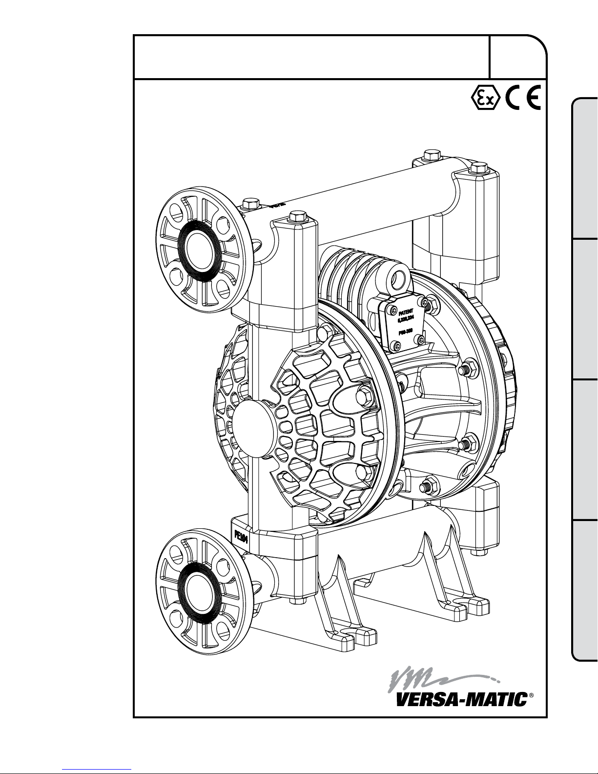
1" Elima-Matic Bolted Non-Metallic – ATEX
with Metallic Center Sections
E1 Non-Metallic Pumps
• Conductive Polypropylene
Original Instructions
E1
1: PUMP SPECS2: INSTAL & OP3: EXP VIEW4: WARRANTY
Service & Operating Manual
Versa-Matic
800 North Main Street, Mansfield, OH 44902 USA • Phone: (419) 526-7296 • www.versamatic.com
VERSA-MATIC
®
• Warren Rupp, Inc. • A Unit of IDEX Corporation
© Copyright 2014 Warren Rupp, Inc. All rights reserved
Page 2
Safety Information
IMPORTANT
Read the safety warnings and instructions in this manual
before pump installation and start-up. Failure to comply with
the recommendations stated in this manual could damage the
pump and void factory warranty.
When the pump is used for materials that tend to settle out
or solidify, the pump should be ushed after each use to
prevent damage. In freezing temperatures the pump should be
completely drained between uses.
CAUTION
Before pump operation, inspect all fasteners for loosening
caused by gasket creep. Retighten loose fasteners to prevent
leakage. Follow recommended torques stated in this manual.
Nonmetallic pumps and plastic components are not UV
stabilized. Ultraviolet radiation can damage these parts and
negatively affect material properties. Do not expose to UV light
for extended periods of time.
WARNING
Pump not designed, tested or certied to be powered by
compressed natural gas. Powering the pump with natural
gas will void the warranty.
WARNING
When used for toxic or aggressive uids, the pump should
always be ushed clean prior to disassembly.
Before maintenance or repair, shut off the compressed air line,
bleed the pressure, and disconnect the air line from the pump.
Be certain that approved eye protection and protective clothing
are worn at all times. Failure to follow these recommendations
may result in serious injury or death.
Airborne particles and loud noise hazards. Wear eye and ear
protection.
In the event of diaphragm rupture, pumped material may enter
the air end of the pump, and be discharged into the atmosphere.
If pumping a product that is hazardous or toxic, the air exhaust
must be piped to an appropriate area for safe containment.
Take action to prevent static sparking. Fire or explosion can
result, especially when handling ammable liquids. The pump,
piping, valves, containers and other miscellaneous equipment
must be properly grounded.
This pump is pressurized internally with air pressure during
operation. Make certain that all fasteners are in good condition
and are reinstalled properly during reassembly.
kg
Use safe practices when lifting
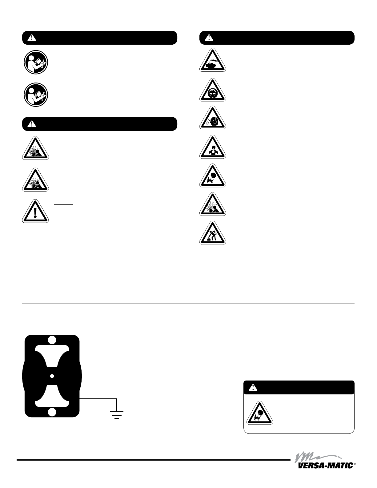
Grounding the Pump
To be fully groundable, the pumps must be ATEX Compliant. Refer to the nomenclature page for ordering information.
Optional 8 foot long (244 centimeters) Ground Strap is available for easy ground connection.
To reduce the risk of static electrical sparking, this pump must be grounded. Check the local
electrical code for detailed grounding instruction and the type of equipment required.
Refer to nomenclature page for ordering information.
WARNING
Take action to prevent static sparking.
Fire or explosion can result, especially
when handling ammable liquids. The
pump, piping, valves, containers or
other miscellaneous equipment must
be grounded.
ww w. ve rs am ati c. co m
e1nmdlCsmATEX-rev0614
Page 3
Table of Contents
SECTION 1: PUMP SPECIFICATIONS ................1
• Nomenclature
• Performance
• Materials
• Dimensional Drawings
SECTION 2: INSTALLATION & OPERATION ......5
• Principle of Pump Operation
• Typical Installation Guide
• Troubleshooting
SECTION 3: EXPLODED VIEW ...........................8
• Composite Drawings
• Parts List
• Materials Code
1: PUMP SPECS2: INSTAL & OP3: EXP VIEW4: WARRANTY
SECTION 4: WARRANTY & CERTIFICATES ....10
• Warranty
• EC Declaration of Conformity - Machinery
• EC Declaration of Conformity - ATEX
e1nmdlCsmATEX-rev0614
ww w. ve rs am ati c. co m
Page 4
Explanation of Pump Nomenclature
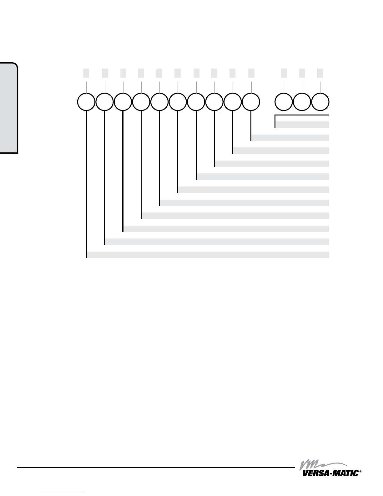
VERSA-MATIC® MODEL IDENTIFICATION CODES
Your Serial #: (ll in from pump nameplate) _____________________________________
1: PUMP SPECS
Your Model #:
(ll in from pump
nameplate)
__ __ __ __ __ __ __ __ __ __ __ __ __
Model #:
X X X X X X X X X X
Construction Design
Valve Seat Material/Valve Seat O-ring Material
Valve Ball Material
Diaphragm Series
Diaphragm Material
Non-Wetted Parts
Wetted Parts
Pump Size
-
X X X
Options (if applicable)
Revision Level
Model
Model Pump Size Wetted Parts Non-Wetted Parts Diaphragm Material
E Elima-Matic 6 1/4" A Aluminum A Aluminum 1 Neoprene
U Ultra-Matic 8 3/8" C Cast Iron S Stainless Steel 2 Nitrile (Nitrile)
V V-Series 5 1/2" S Stainless Steel P Polypropylene 3 FKM (Fluorocarbon)
RE AirVantage 7 3/4" H Alloy C G Groundable Acetal 4 EPDM
1 1" P Polypropylene Z PTFE-coated Aluminum 5 PTFE
4 1-1/4" or 1-1/2" K Kynar J Nickel-plated Aluminum 6 Santoprene XL
2 2" G Groundable Acetal C Cast Iron 7 Hytrel
3 3" B Aluminum (screen mount) Q Epoxy-Coated Aluminum 9 Geolast
Diaphragm Series Valve Ball Material Valve Seat/Valve Seat O-Ring Material Construction Design
R Rugged 1 Neoprene 1 Neoprene 9 Bolted
D Dome 2 Nitrile 2 Nitrile 0 Clamped
X Thermo-Matic 3 (FKM) Fluorocarbon 3 (FKM) Fluorocarbon
T Tef-Matic (2-piece) 4 EPDM 4 EPDM
B Versa-Tuff (1-piece) 5 PTFE 5 PTFE
F FUSION (one-piece 6 Santoprene XL 6 Santoprene XL
integrated plate) 7 Hytrel 7 Hytrel
8 Polyurethane 8 Polyurethane
9 Geolast 9 Geolast
A Acetal A Aluminum w/ PTFE O-Rings
S Stainless Steel S Stainless Steel w/ PTFE O-Rings
C Carbon Steel w/ PTFE O-Rings
H Alloy C w/ PTFE O-Rings
T PTFE Encapsulated Silicone O-Rings
1 • Model E1 Non-Metallic Bolted
ww w. ve rs am ati c. co m
e1nmdlCsmATEX-rev0614
Page 5
Materials
Material Prole:
CAUTION! Operating temperature limitations are as follows:
Conductive Acetal: Tough, impact resistant, ductile. Good
abrasion resistance and low friction surface. Generally inert, with
good chemical resistance except for strong acids and oxidizing
agents.
EPDM: Shows very good water and chemical resistance. Has
poor resistance to oils and solvents, but is fair in ketones and
alcohols.
FKM: (Fluorocarbon) Shows good resistance to a wide range
of oils and sovents; especially all aliphatic, aromatic and
halogenated hydrocarbons, acids, animal and vegetable oils.
Hot water or hot aqueous solutions (over 70°F) will attack FKM.
Hytrel®: Good on acids, bases, amines and glycols at room
temperatures only.
Neoprene: All purpose. Resistance to vegetable oils. Generally
not affected by moderate chemicals, fats, greases and many
oils and solvents. Generally attacked by strong oxidizing acids,
ketones, esters and nitro hydrocarbons and chlorinated aromatic
hydrocarbons.
Nitrile: General purpose, oil-resistant. Shows good solvent, oil,
water and hydraulic uid resistance. Should not be used with
highly polar solvents like acetone and MEK, ozone, chlorinated
hydrocarbons and nitro hydrocarbons.
Nylon: 6/6 High strength and toughness over a wide
temperature range. Moderate to good resistance to fuels, oils
and chemicals.
Operating
Temperatures:
Max. Min.
190°F
88°C
280°F
138°C
350°F
177°C
220°F
104°C
200°F
93°C
190°F
88°C
180°F
82°C
-20°F
-29°C
-40°F
-40°C
-40°F
-40°C
-20°F
-29°C
-10°F
-23°C
-10°F
-23°C
32°F
0°C
Polypropylene: A thermoplastic polymer. Moderate tensile
and ex strength. Resists stong acids and alkali. Attacked by
chlorine, fuming nitric acid and other strong oxidizing agents.
PVDF: (Polyvinylidene Fluoride) A durable uoroplastic with
excellent chemical resistance. Excellent for UV applications.
High tensile strength and impact resistance.
Santoprene®: Injection molded thermoplastic elastomer with
no fabric layer. Long mechanical ex life. Excellent abrasion
resistance.
UHMW PE: A thermoplastic that is highly resistant to a broad
range of chemicals. Exhibits outstanding abrasion and impact
resistance, along with environmental stress-cracking resistance.
Urethane: Shows good resistance to abrasives. Has poor
resistance to most solvents and oils.
Virgin PTFE: (PFA/TFE) Chemically inert, virtually impervious.
Very few chemicals are known to chemically react with PTFE;
molten alkali metals, turbulent liquid or gaseous uorine and
a few uoro-chemicals such as chlorine triuoride or oxygen
diuoride which readily liberate free uorine at elevated
temperatures.
Maximum and Minimum Temperatures are the limits for which these materials can be operated.
Temperatures coupled with pressure affect the longevity of diaphragm pump components.
Maximum life should not be expected at the extreme limits of the temperature ranges.
180°F
82°C
250°F
121°C
275°F
135°C
180°F
82°C
150°F
66°C
220°F
104°C
32°F
0°C
0°F
-18°C
-40°F
-40°C
-35°F
-37°C
32°F
0°C
-35°F
-37°C
Metals:
Alloy C: Equal to ASTM494 CW-12M-1 specication for nickel and nickel alloy.
Stainless Steel: Equal to or exceeding ASTM specication A743 CF-8M for corrosion
resistant iron chromium, iron chromium nickel and nickel based alloy castings for
general applicaitons. Commonly referred to as 316 Stainless Steel in the pump industry.
For specic applications, always consult the Chemical Resistance Chart.
1: PUMP SPECS
AFTERMARKET PARTS
RIGHT PART, RIGHT NOW
Pumper Parts is your single source for parts that
t Air-Operated Double Diaphragm (AODD) pumps
• Wilden
• ARO
• Yamada
Designed to perform equal to or greater
than original equipment manufacture.
Pumper Parts and its products are not affiliated with any of the original equipment manufacturers referenced herein. All original equipment manufacturers’ names, colors, pictures, descriptions and part numbers are used for identification
purposes only. Pumper Parts® is a registered trade name of IDEX Corporation. All other trademarks, registered trademarks and product names are the property of their respective owners. Yamada® is a registered trademark of
Yamada Corporation. ARO® is a registered trade name of Ingersoll-Rand Company. Wilden® is a registered trade name of Wilden Pump and Engineering Company, a Dover Resources Company.
®
®
®
Phone: (419) 526-7296
info@pum perparts.com
www.pumperparts.com
e1nmdlCsmATEX-rev0614
ww w. ve rs am ati c. co m
Model E1 Non-Metallic Bolted • 2
Page 6
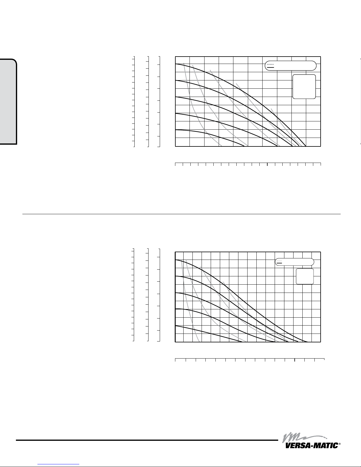
Performance
E1 1" Bolted Plastic
Rubber and TPE Fitted
Flow Rate
Adjustable to ......0-45 gpm (170.3 LPM)
Port Size
Suction .........1" 150# ANSI/DIN Flange
Discharge.......1" 150# ANSI/DIN Flange
Air Inlet ......................3/8" NPT
Air Exhaust ..................1/2" NPT
Suction Lift
Dry ........................15' (4.5 m)
Wet........................31' (9.4 m)
Max Solid Size (Diameter)
1: PUMP SPECS
........................1/8" (3.2 mm)
Max Noise Level .............88 dB(A)
Shipping Weights
Conductive Polypropylene ...21 lbs (9.5 kg)
75
240
70
220
65
60
200
55
180
50
160
45
140
40
120
35
30
100
25
80
20
60
15
40
10
20
5
0
0
Meters Feet
100
7
6
80
5
60
4
3
40
2
Discharge Head in PSI
20
1
0
0
BAR
0 10 20 30 40 50
0 20 40 60 80 100 120 140 160 180
Displacement Per Stroke, 0
5
10
20
30
40
Capacity in U.S. Gallons Per Minute
.11 Gal. (0.42 L)
AIR CONSUMPTION IN SCFM
AIR PRESSURE IN PSI
SCFM M3/HR
5 8.5
10 17
20 34
30 51
40 68
Capacity in Liters Per Minute
NOTE: Performance based on the following: elastomeric tted pump, ooded suction, water at
ambient conditions. The use of other materials and varying hydraulic conditions may result in
deviations in excess of 5%.
E1 1" Bolted Plastic
PTFE Fitted
Flow Rate
Adjustable to ......0-35 gpm (132.5 LPM)
Port Size
Suction .........1" 150# ANSI/DIN Flange
Discharge.......1" 150# ANSI/DIN Flange
Air Inlet ......................3/8" NPT
Air Exhaust ..................1/2" NPT
Suction Lift
Dry .........................5' (2.1 m)
Wet........................30' (9.4 m)
Max Solid Size (Diameter)
........................1/8" (3.2 mm)
Max Noise Level .............93 dB(A)
Shipping Weights
Conductive Polypropylene ...21 lbs (9.5 kg)
75
240
70
220
65
200
60
55
180
50
160
45
140
40
120
35
100
30
25
80
20
60
15
40
10
20
5
0
0
Meters Feet
7
6
5
4
3
2
1
0
BAR
5 10
100
80
60
40
Discharge Head in PSI
20
0
0 5 10 15 20 25 30 35 40
Displacement Per Stroke,
20
30
.05 Gal. (0.19 L)
AIR CONSUMPTION IN SCFM
AIR PRESSURE IN PSI
SCFM M3/HR
5 8.5
10 17
20 34
30 51
Capacity in U.S. Gallons Per Minute
0 20 40 60 80 100 120 140
Capacity in Liters Per Minute
NOTE: Performance based on the following: elastomeric tted pump, ooded suction, water at
ambient conditions. The use of other materials and varying hydraulic conditions may result in
deviations in excess of 5%.
3 • Model E1 Non-Metallic Bolted
ww w. ve rs am ati c. co m
e1nmdlCsmATEX-rev0614
Page 7
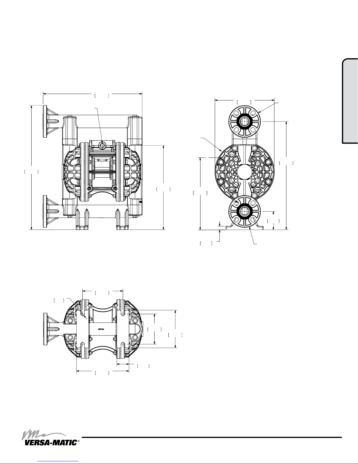
Dimensional Drawings
13.52
343.41
11.48
291.47
16.94
430.15
3/8" NPT
AIR INLET
16.94
430.15
3/8" NPT
AIR INLET
14.75
374.65
9.81
249.22
8.13
206.38
1" ANSI 150# / DIN 325
DISCHARGE FLANGE
1/2" NPT
AIR EXHAUST
E1 Non-Metallic Bolted
Dimensions in inches (mm dimensions in brackets)
The dimensions on this drawing are for reference only. A certied drawing can be requested if physical dimensions are needed.
13.52
343.41
3/8" NPT
AIR INLET
1/2" NPT
AIR EXHAUST
16.94
430.15
8.13
206.38
1" ANSI 150# / DIN 325
DISCHARGE FLANGE
14.75
374.65
1: PUMP SPECS
R
6.35
.25
5.50
139.70
7.16
181.86
4.12
104.65
1.66
42.16
11.48
291.47
5.13
130.30
9.81
249.22
.49
12.45
2.50
63.50
1" ANSI 150# / DIN 325
SUCTION FLANGE
e1nmdlCsmATEX-rev0614
ww w. ve rs am ati c. co m
Model E1 Non-Metallic Bolted • 4
Page 8
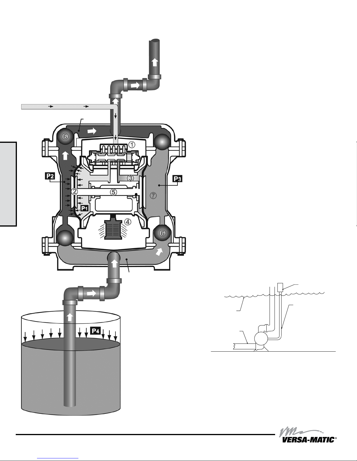
Principle of Pump Operation
SAFE AIR
EXHAUST
DISPOSAL
AREA
MUFFLER
Air-Operated Double Diaphragm (AODD) pumps are powered
by compressed air or nitrogen.
2: INSTAL & OP
Discharge
Stroke
Air Line
Discharged
Fluid
Suction
Stroke
The main directional (air) control valve
compressed air to an air chamber, exerting uniform pressure
over the inner surface of the diaphragm
the exhausting air
is directed through the air valve assembly(s) to an exhaust
port
.
④
As inner chamber pressure
pressure
together creating discharge on one side and suction on the
opposite side. The discharged and primed liquid’s directions
are controlled by the check valves (ball or ap)
The pump primes as a result of the suction stroke. The
suction stroke lowers the chamber pressure
the chamber volume. This results in a pressure differential
necessary for atmospheric pressure
through the suction piping and across the suction side check
valve and into the outer uid chamber
Suction (side) stroking also initiates the reciprocating
(shifting, stroking or cycling) action of the pump. The suction
diaphragm’s movement is mechanically pulled through its
stroke. The diaphragm’s inner plate makes contact with an
actuator plunger aligned to shift the pilot signaling valve.
Once actuated, the pilot valve sends a pressure signal to the
opposite end of the main directional air valve, redirecting the
compressed air to the opposite inner chamber.
(P2), the rod
from behind the opposite diaphragm
③
(P1) exceeds liquid chamber
connected diaphragms shift
⑤
distributes
①
. At the same time,
②
orientation.
⑥
(P3) increasing
(P4) to push the uid
.
⑦
5 • Model E1 Non-Metallic Bolted
Primed
Fluid
SUBMERGED ILLUSTRATION
MUFFLER
LIQUID
LEVEL
SUCTION
LINE
Pump can be submerged if the pump materials of construction
are compatible with the liquid being pumped. The air exhaust
must be piped above the liquid level. When the pumped product
source is at a higher level than the pump (ooded suction
condition), pipe the exhaust higher than the product source to
prevent siphoning spills.
ww w. ve rs am ati c. co m
1" DIAMETER AIR
EXHAUST PIPING
e1nmdlCsmATEX-rev0614
Page 9
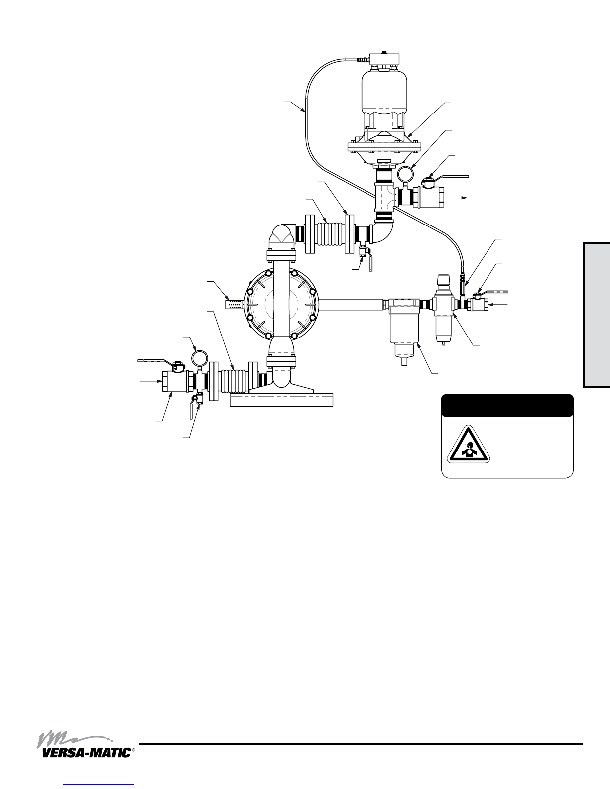
Recommended Installation Guide
Available Accessories:
1. Surge Suppressor
2. Filter/Regulator
3. Air Dryer
Unregulated Air
Supply to Surge
Suppressor
1
Surge Suppressor
Pressure Gauge
Shut-Off Valve
Note: Surge Suppressor and
Piping must be supported after
the exible connection.
(Optional Piped Exhaust)
Flexible Connector
Vacuum
Gauge
Suction
Shut-Off Valve
Drain Port
Muffler
Pipe Connection
(Style Optional)
Flexible Connector
Drain Port
Discharge
Check
Valve
Shut-Off
Valve
2
Air Inlet
3
Filter Regulator
P/N: 020.V107.000
Air Dryer
2: INSTAL & OP
CAUTION
The air exhaust should
be piped to an area
for safe disposition
of the product being
pumped, in the event of
a diaphragm failure.
Installation And Start-Up
Locate the pump as close to the product being pumped as possible. Keep the suction line length and number of ttings to a minimum. Do not reduce the suction line
diameter.
Air Supply
Connect the pump air inlet to an air supply with sufcient capacity and pressure to achieve desired performance. A pressure regulating valve should be installed to
insure air supply pressure does not exceed recommended limits.
Air Valve Lubrication
The air distribution system is designed to operate WITHOUT lubrication. This is the standard mode of operation. If lubrication is desired, install an air line lubricator
set to deliver one drop of SAE 10 non-detergent oil for every 20 SCFM (9.4 liters/sec.) of air the pump consumes. Consult the Performance Curve to determine air
consumption.
Air Line Moisture
Water in the compressed air supply may cause icing or freezing of the exhaust air, causing the pump to cycle erratically or stop operating. Water in the air supply can
be reduced by using a point-of-use air dryer.
Air Inlet And Priming
To start the pump, slightly open the air shut-off valve. After the pump primes, the air valve can be opened to increase air ow as desired. If opening the valve
increases cycling rate, but does not increase the rate of ow, cavitation has occurred. The valve should be closed slightly to obtain the most efcient air ow to pump
ow ratio.
e1nmdlCsmATEX-rev0614
ww w. ve rs am ati c. co m
Model E1 Non-Metallic Bolted • 6
Page 10
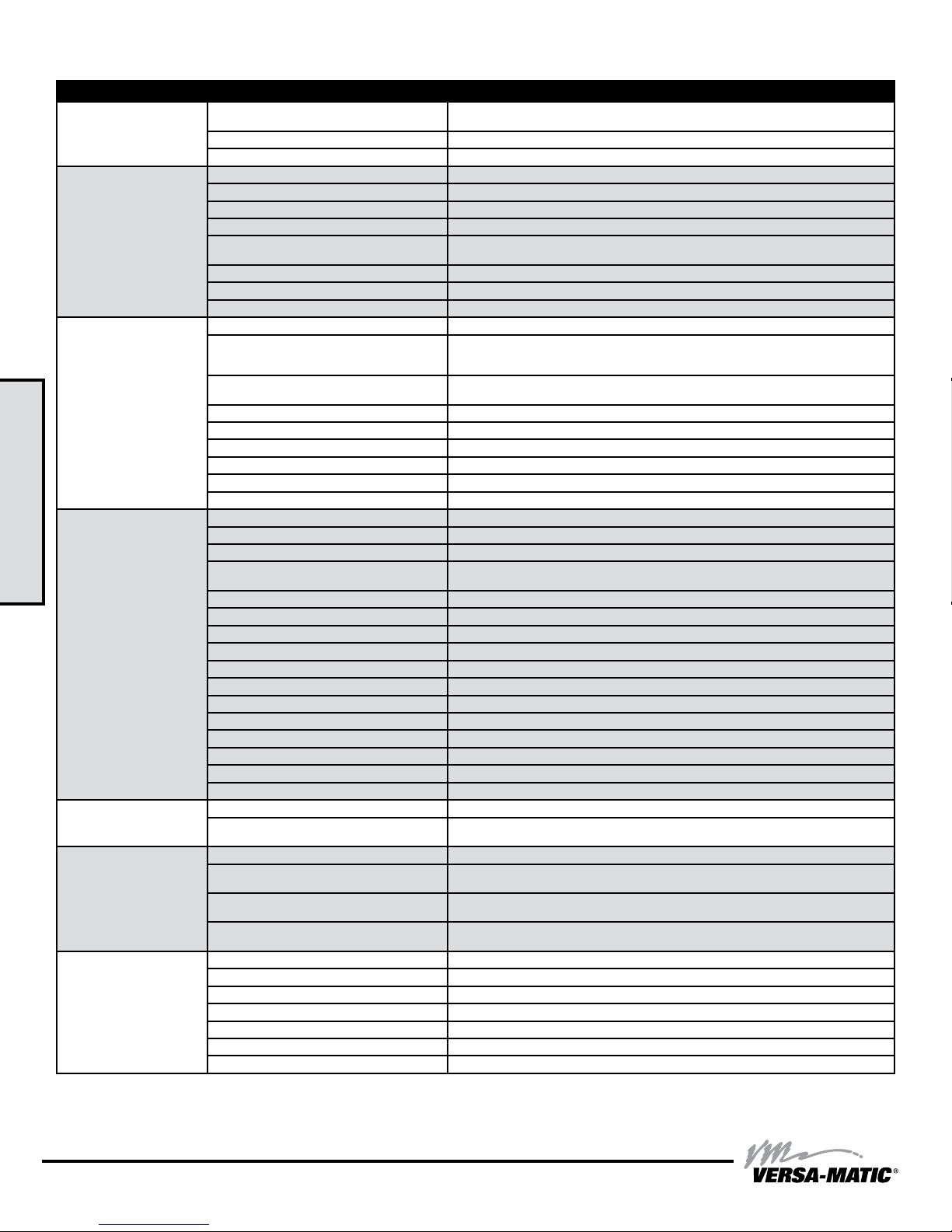
Troubleshooting Guide
Symptom: Potential Cause(s): Recommendation(s):
Pump Cycles Once
Pump Will Not Operate
/ Cycle
Pump Cycles and Will
Not Prime or No Flow
Pump Cycles Running
2: INSTAL & OP
Sluggish/Stalling,
Flow Unsatisfactory
Product Leaking
Through Exhaust
Premature Diaphragm
Failure
Unbalanced Cycling
Deadhead (system pressure meets or exceeds air
supply pressure).
Air valve or intermediate gaskets installed incorrectly. Install gaskets with holes properly aligned.
Bent or missing actuator plunger. Remove pilot valve and inspect actuator plungers.
Pump is over lubricated. Set lubricator on lowest possible setting or remove. Units are designed for lube free operation.
Lack of air (line size, PSI, CFM). Check the air line size and length, compressor capacity (HP vs. cfm required).
Check air distribution system. Disassemble and inspect main air distribution valve, pilot valve and pilot valve actuators.
Discharge line is blocked or clogged manifolds. Check for inadvertently closed discharge line valves. Clean discharge manifolds/piping.
Deadhead (system pressure meets or exceeds air
supply pressure).
Blocked air exhaust mufer. Remove mufer screen, clean or de-ice, and re-install.
Pumped uid in air exhaust mufer. Disassemble pump chambers. Inspect for diaphragm rupture or loose diaphragm plate assembly.
Pump chamber is blocked. Disassemble and inspect wetted chambers. Remove or ush any obstructions.
Cavitation on suction side. Check suction condition (move pump closer to product).
Check valve obstructed. Valve ball(s) not seating
properly or sticking.
Valve ball(s) missing (pushed into chamber or
manifold).
Valve ball(s)/seat(s) damaged or attacked by product. Check Chemical Resistance Guide for compatibility.
Check valve and/or seat is worn or needs adjusting. Inspect check valves and seats for wear and proper setting. Replace if necessary.
Suction line is blocked. Remove or ush obstruction. Check and clear all suction screens or strainers.
Excessive suction lift. For lifts exceeding 20’ of liquid, lling the chambers with liquid will prime the pump in most cases.
Suction side air leakage or air in product. Visually inspect all suction-side gaskets and pipe connections.
Pumped uid in air exhaust mufer. Disassemble pump chambers. Inspect for diaphragm rupture or loose diaphragm plate assembly.
Over lubrication. Set lubricator on lowest possible setting or remove. Units are designed for lube free operation.
Icing. Remove mufer screen, de-ice, and re-install. Install a point of use air drier.
Clogged manifolds. Clean manifolds to allow proper air ow
Deadhead (system pressure meets or exceeds air
supply pressure).
Cavitation on suction side. Check suction (move pump closer to product).
Lack of air (line size, PSI, CFM). Check the air line size, length, compressor capacity.
Excessive suction lift. For lifts exceeding 20’ of liquid, lling the chambers with liquid will prime the pump in most cases.
Air supply pressure or volume exceeds system hd. Decrease inlet air (press. and vol.) to the pump. Pump is cavitating the uid by fast cycling.
Undersized suction line. Meet or exceed pump connections.
Restrictive or undersized air line. Install a larger air line and connection.
Suction side air leakage or air in product. Visually inspect all suction-side gaskets and pipe connections.
Suction line is blocked. Remove or ush obstruction. Check and clear all suction screens or strainers.
Pumped uid in air exhaust mufer. Disassemble pump chambers. Inspect for diaphragm rupture or loose diaphragm plate assembly.
Check valve obstructed. Disassemble the wet end of the pump and manually dislodge obstruction in the check valve pocket.
Check valve and/or seat is worn or needs adjusting. Inspect check valves and seats for wear and proper setting. Replace if necessary.
Entrained air or vapor lock in chamber(s). Purge chambers through tapped chamber vent plugs. Purging the chambers of air can be dangerous.
Diaphragm failure, or diaphragm plates loose. Replace diaphragms, check for damage and ensure diaphragm plates are tight.
Diaphragm stretched around center hole or bolt holes. Check for excessive inlet pressure or air pressure. Consult Chemical Resistance Chart for compatibility
Cavitation. Enlarge pipe diameter on suction side of pump.
Excessive ooded suction pressure. Move pump closer to product. Raise pump/place pump on top of tank to reduce inlet pressure.
Misapplication (chemical/physical incompatibility). Consult Chemical Resistance Chart for compatibility with products, cleaners, temperature limitations
Incorrect diaphragm plates or plates on backwards,
installed incorrectly or worn.
Excessive suction lift. For lifts exceeding 20’ of liquid, lling the chambers with liquid will prime the pump in most cases.
Undersized suction line. Meet or exceed pump connections.
Pumped uid in air exhaust mufer. Disassemble pump chambers. Inspect for diaphragm rupture or loose diaphragm plate assembly.
Suction side air leakage or air in product. Visually inspect all suction-side gaskets and pipe connections.
Check valve obstructed. Disassemble the wet end of the pump and manually dislodge obstruction in the check valve pocket.
Check valve and/or seat is worn or needs adjusting. Inspect check valves and seats for wear and proper setting. Replace if necessary.
Entrained air or vapor lock in chamber(s). Purge chambers through tapped chamber vent plugs.
Increase the inlet air pressure to the pump. Pump is designed for 1:1 pressure ratio at zero ow.
(Does not apply to high pressure 2:1 units).
Increase the inlet air pressure to the pump. Pump is designed for 1:1 pressure ratio at zero ow.
(Does not apply to high pressure 2:1 units).
Disassemble the wet end of the pump and manually dislodge obstruction in the check valve pocket.
Clean out around valve ball cage and valve seat area. Replace valve ball or valve seat if damaged.
Use heavier valve ball material.
Worn valve ball or valve seat. Worn ngers in valve ball cage (replace part). Check Chemical
Resistance Guide for compatibility.
Increase the inlet air pressure to the pump. Pump is designed for 1:1 pressure ratio at zero ow.
(Does not apply to high pressure 2:1 units).
with products, cleaners, temperature limitations and lubrication.
Install Back pressure device (Tech bulletin 41r). Add accumulation tank or pulsation dampener.
and lubrication.
Check Operating Manual to check for correct part and installation. Ensure outer plates have not been
worn to a sharp edge.
For additional troubleshooting tips contact After Sales Support at [email protected] or 419-524-8388
7 • Model E1 Non-Metallic Bolted
ww w. ve rs am ati c. co m
e1nmdlCsmATEX-rev0614
Page 11
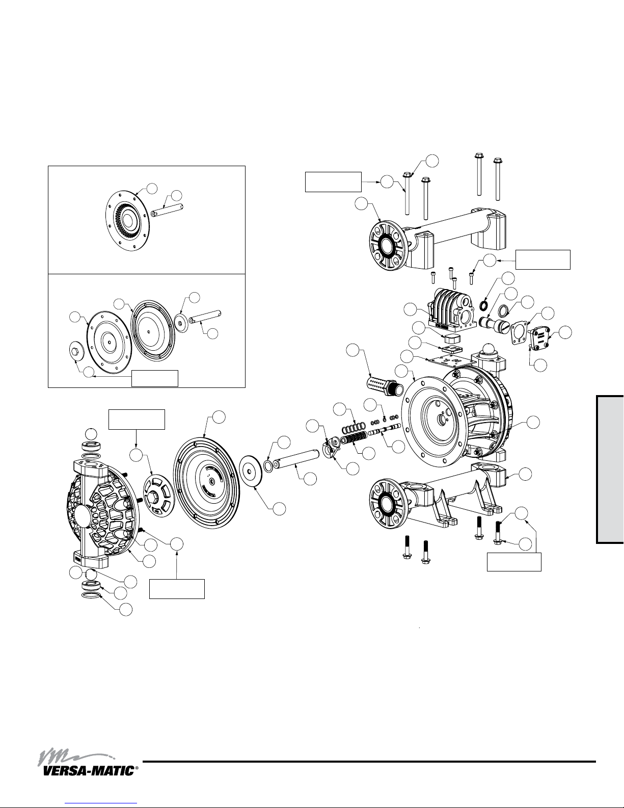
Composite Repair Parts Drawing
1
2
3
4
5
6
7
8
9
10
11
12
13
14
15
16
10
17
18
19
20
22
23
24
25
25
26
27
28
29
30
31
32
33
34
29
29
10
37
40
38
41
38
40
41
39
OPTIONAL CP MANIFOLD ASSEMBLY
35
36
Torque Setting:
120 in-lbs.
Torque Setting:
180 in-lbs.
Torque Setting:
120 in-lbs.
Torque Setting:
180 in-lbs.
Torque Setting:
40 in-lbs.
FUSION DIAPHRAGM ASY
20
19
35
Torque Setting:
120 in-lbs.
29
32
31
36
20
23
25
PTFE TWO-PIECE DIAPHRAGM ASY
21
Torque Setting:
180 in-lbs.
Torque Setting:
180 in-lbs.
23
28
29
27
25
26
Torque Setting:
180 in-lbs.
24
10
Torque Setting:
40 in-lbs.
4
22
1
19
17
7
8
9
11
13
20
15
10
18
14
16
12
19
22
2
Torque Setting:
120 in-lbs.
3
6
5
10
30
33
3: EXP VIEW
34
29
e1nmdlCsmATEX-rev0614
ww w. ve rs am ati c. co m
Model E1 Non-Metallic Bolted • 8
Page 12
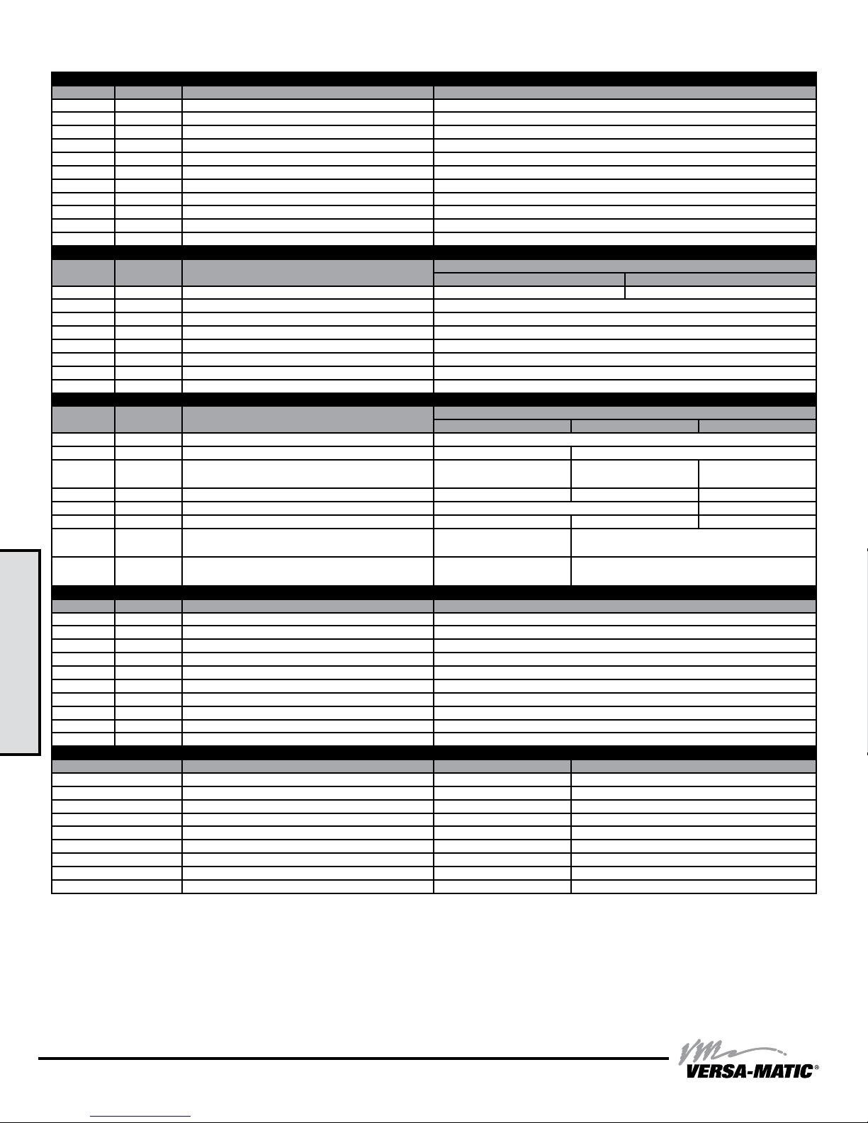
Composite Repair Parts List
Item # Qty. Description Part Number
- 1 Air Valve Assembly (includes items 1-10) 031.V006.156
1 1 Valve Body P98-102UB
2 1 Valve Spool Assembly (Includes items 3&4) P98-105UB ASY
3 1 Large Valve Spool U-Cup P98-105B
4 1 Small Valve Spool U-Cup P98-105A
5 2 Metal End Cap P98-300
6 2 End Cap Gasket (for metal) P98-110
7 1 CT Air Diverter P98-105CT
8 1 Air Diverter Plate P98-106
9 1 Air Valve Gasket P98-111UB
10 12 Mounting Screws (8 included on Air Valve Assembly) S1001
Item # Qty. Description
11 1 Center Section 114.V001.157 114.V001.332
12 1 Pilot Spool ASY (includes item 13) 775.V005.000
13 7 Pilot Spool O-Rings 560.023.358
14 1 Pilot Valve Sleeve ASY (includes item 15) 755.V004.000
15 6 Pilot Valve Sleeve O-Rings 560.101.358
16 2 Shaft/Pilot Retainer 670.V002.554
10 4 Retainer Screw S1001
17 1 Mufer VTM-4A
Item # Qty. Description
18 2 Main Shaft O-Ring P50-403
19 1 Main Shaft 685.V001.120 P50-108
20 2 Diaphragm
21 2 Back-Up Diaphragm N/A V183TB N/A
22 2 Inner Diaphragm Plate V181C N/A
23 2 Outer Diaphragm Plate PE113 PV181TO N/A
24 4 Valve Seat O-Ring
25 4 Valve Ball
Item # Qty. Description Part Number
26 4 Valve Seat PE108
27 2 Water Chamber PE104-ATEX
28 16 Water Chamber Bolt SV187A
29 16 Water Chamber Washer SV189C
3: EXP VIEW
30 16 Water Chamber Nut SV185B
31 1 Discharge Manifold PE120-ATEX
32 4 Discharge Manifold Bolt E120A
33 1 Suction Manifold PE120F-ATEX
34 4 Suction Manifold Bolt E120B
29 8 Manifold Washer SV189C
Material Diaphragm P/N Valve Ball P/N O-Ring P/N
Neoprene V183N-1 V191N N/A
Buna Nitrile V183BN-1 V191BN V90BN
Viton V183VT-1 V191VT V90VT
Nordel V183ND-1 V191ND V90ND
Santoprene V183TPEXL-1 V191TPEXL V190XL
Hytrel V183TPEFG V191TPEFG N/A
Geolast V183G V191G N/A
Acetal N/A V191A N/A
Stainless Steel N/A V191SS N/A
Air Valve Assembly
Center Section Assembly
Aluminum Nickel Plated
Diaphragm Assembly / Elastomers
TPE/RUBBER PTFE 2-Piece PTFE Fusion
"V183xx-1
(See Below Material Chart)"
"V90xx
(See Below Material Chart)"
"V191xx
(See Below Material Chart)"
Wet End Assembly
Elastomer Material Specications
Part Number
Part Number
V183TF-1 V183F
SV190TF
V191TF
9 • Model E1 Non-Metallic Bolted
ww w. ve rs am ati c. co m
e1nmdlCsmATEX-rev0614
Page 13
Written Warranty
5 - YEAR Limited Product Warranty
Quality System ISO9001 Certied • Environmental Management Systems ISO14001 Certied
Versa-Matic warrants to the original end-use purchaser that no product sold by
Versa-Matic that bears a Versa-Matic brand shall fail under normal use and service due to a defect in material
or workmanship within ve years from the date of shipment from Versa-Matic’s factory.
~ See complete warranty at http://www.versamatic.com/pdfs/VM%20Product%20Warranty.pdf ~
DECLARATION OF CONFORMITY
DECLARATION DE CONFORMITE • DECLARACION DE CONFORMIDAD • ERKLÄRUNG BEZÜGLICH EINHALTUNG DER VORSCHRIFTEN
MANUFACTURED BY:
FABRIQUE PAR:
FABRICADA POR:
HERGESTELLT VON:
FABBRICATO DA:
VERVAARDIGD DOOR:
TILLVERKAD AV:
FABRIKANT:
VALMISTAJA:
PRODUSENT:
FABRICANTE:
DICHIARAZIONE DI CONFORMITÀ • CONFORMITEITSVERKLARING • DEKLARATION OM ÖVERENSSTÄMMELSE
EF-OVERENSSTEMMELSESERKLÆRING • VAATIMUSTENMUKAISUUSVAKUUTUS • SAMSVARSERKLÄRING
DECLARAÇAO DE CONFORMIDADE
VERSA-MATIC
Warren Rupp, Inc.
A Unit of IDEX Corporation
800 North Main Street
P.O. Box 1568
Mansfield, OH 44901-1568 USA
Tel: 419-526-7296
Fax: 419-526-7289
®
PUMP MODEL SERIES: E SERIES, V SERIES, VT SERIES, VSMA3, SPA15,
RE SERIES AND U2 SERIES
This product complies with the following European Community Directives:
Ce produit est conforme aux directives de la Communauté européenne suivantes:
Este producto cumple con las siguientes Directrices de la Comunidad Europea:
Dieses produkt erfüllt die folgenden Vorschriften der Europäischen Gemeinschaft:
Questo prodotto è conforme alle seguenti direttive CEE:
Dir produkt voldoet aan de volgende EG-richtlijnen:
Denna produkt överensstämmer med följande EU direktiv:
Versa-Matic, Inc., erklærer herved som fabrikant, at ovennævnte produkt er i overensstemmelse med bestemmelserne i Direkktive:
Tämä tuote täyttää seuraavien EC Direktiivien vaatimukstet:
Dette produkt oppfyller kravene til følgende EC Direktiver:
Este produto está de acordo com as seguintes Directivas comunitárias:
2006/42/EC
on Machinery, according
to Annex VIII
This product has used the following harmonized standards to verify conformance: EN809:1998+
Ce materiel est fabriqué selon les normes harmonisées suivantes, afin d’ en garantir la conformité:
Este producto cumple con las siquientes directrices de la comunidad europa:
Dieses produkt ist nach folgenden harmonisierten standards gefertigtworden, die übereinstimmung wird bestätigt:
Questo prodotto ha utilizzato i seguenti standards per verificare la conformita´:
De volgende geharmoniseerde normen werden gehanteerd om de conformiteit van dit produkt te garanderen:
För denna produkt har följande harmoniserande standarder använts för att bekräfta överensstämmelse:
Harmoniserede standarder, der er benyttet:
Tässä tuotteessa on sovellettu seuraavia yhdenmukaistettuja standardeja:
Dette produkt er produsert i overenstemmelse med fløgende harmoniserte standarder:
Este produto utilizou os seguintes padrões harmonizados para varificar conformidade:
AUTHORIZED / APPROVED BY:
Approuve par:
Aprobado por:
Genehmigt von:
approvato da:
Goedgekeurd door:
Underskrift:
Valtuutettuna:
Bemyndiget av:
Autorizado Por:
04/19/2012 REV 07 VMQR 044FM
e1nmdlCsmATEX-rev0614
ww w. ve rs am ati c. co m
Dave Roseberry
Engineering Manager
A1:2009
DATE: August 10, 2011
FECHA:
DATUM:
DATA:
DATO:
PÄIVÄYS:
Model E1 Non-Metallic Bolted • 10
Page 14
EC DECLARATION OF CONFORMITY
in accordance with ANNEX VIII of Directive 94/9/EC - Equipment for use in Potentially Explosive Atmospheres
Date of Issue: 10 May 2014
Technical File No.: 203104000-1410/MER
Quality System Registration No: ISO 9001-2000
Directive: 94/9/EC 23 March 1994 Annex VIII
Conforming Apparatus: Air-Operated Conductive Polypropylene and
Conductive Acetal Double Diaphragm Pumps
for use in Potentially Explosive Atmospheres
Hazardous Location Applied: 1. II 3/2GD c T6*
T6uidsupto80°C
*Whenpumpingnon-conductiveuidstheinternalsurfacesthat
contacttheuidarerestrictedtoExII3GDcT5.Theexternal
surfacesofthepumparestillExII2GDcT5.
Pumps marked with equipment Category II 3/2 G
(internal 3 G / external 2 G), 2D, when used with
non-conductiveuids.ThepumpsareCategoryII2G
whenusedforconductiveuids.
Manufacture: Warren Rupp, Inc., A Unit of IDEX Corporation
800NorthMainStreet,P.O.Box1568
Manseld,OH44901-1568
USA.
OnFileWith: DEKRACerticationB.V.(0344)
Meander1051
6825MJArnhem
The Netherlands
Harmonized Standards Applied: EN 13463-1:2009 Non-Electrical Equipment
PotentiallyExplosiveAtmospheres-Part1Basic
Methods and Requirements
EN13463-5:2011Non-ElectricalEquipmentfor
PotentiallyExplosiveAtmospheres-Part5
Protection by Constructional Safety
Equipments: 1. Elima-Matic Series with any of the following
materials of construction are rated to II 3/2GD c T6:
Conductive Polypropylene and Conductive Acetal
uidhousingswithAluminumorStainlessSteel
air center sections
We hereby certify that the equipment described above conforms with the protection requirements of Council Directive
94/9/EC of 23 March 1994 Annex VIII on the approximation of the laws of the Member States Concerning Equipment
and Protective Systems Intended for use in Potentially Explosive Atmospheres
DATE/OF REVISION/TITLE: Dave Roseberry
29 May 2014 Engineering Manager
VM_DofC_ATEX_Non-Metallic_V_rev0514
 Loading...