

versa INSERTO DOMINO XXS, INSERTO DOMINO USS, INSERTO SEAT DOMINO Series, INSERTO DOMINO US, INSERTO DOMINO UUS Product Technical Specification
...Page 1
www.versainserto.com
PRODUCT TECHNICAL SHEET
INSERTO SEAT DOMINO
This Technical Sheet is to be intended as an integral section of the Inserto Seat Range Instruction Manual.
Before use, it is essential for the professional operator to explain all procedures for a correct commissioning and
a proper maintenance.
1. Commissioning
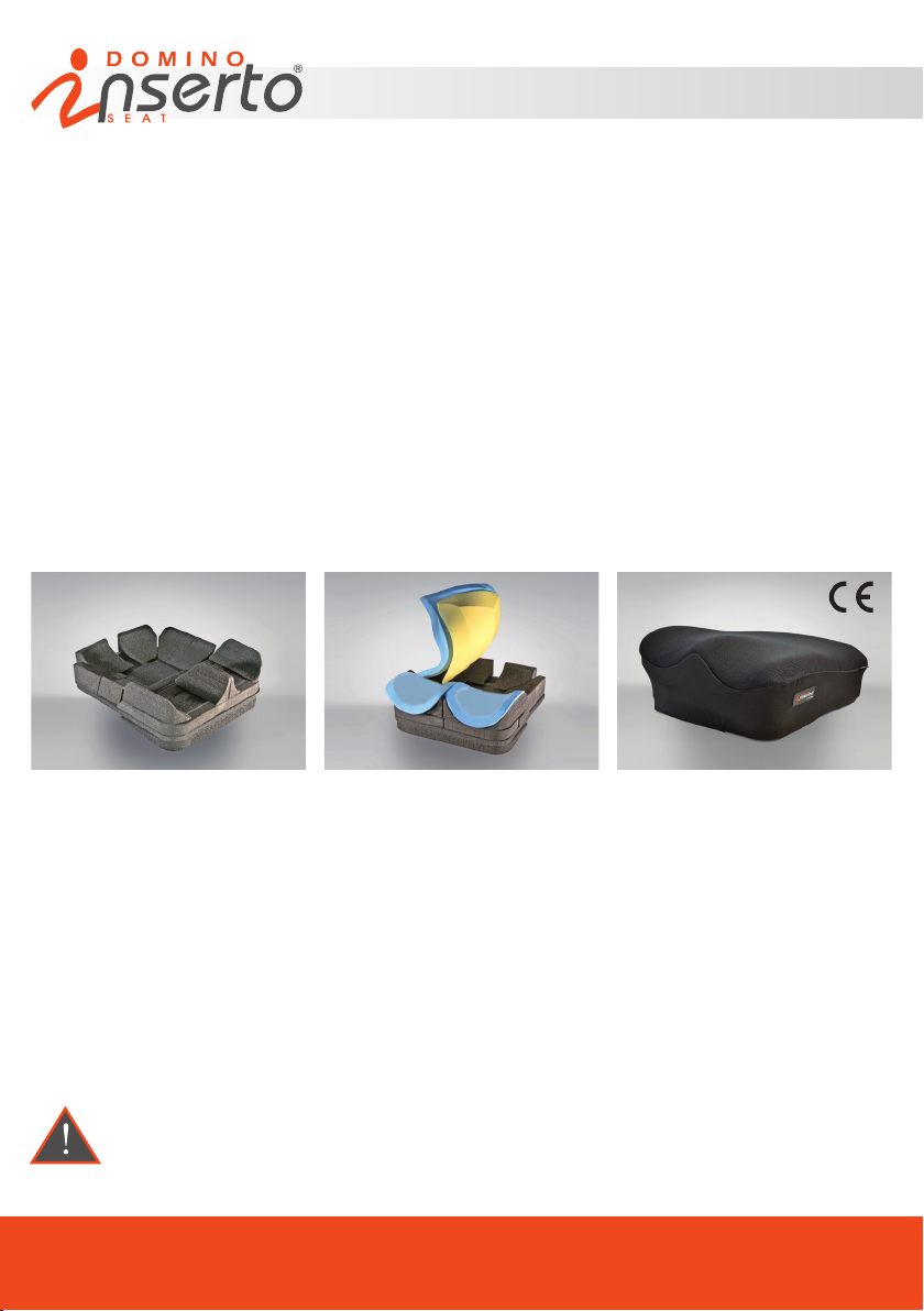
The pelvis positioning system Inserto Seat Domino of Inserto seat Range comes in a form of a kit:
1) A structural kit composed by a at base of construction and 17 closed cells polyethylene inserts, modular
and congurable, useful to individually support or correct the posture of the pelvis during the life time use;
2) A kit of padding (Free Shapes) composed as follows:
- in the posterior part by two overlapped pads: one superior pad made of an open celled foam with low spring
back action to enhance the maximum comfort and the best adaptation as to the body shapes weather to the
structural kit and an inferior pad of anti-decubitus memory foam for the highest protection from decubitus sores.
- in the anterior part by two independent pads (RH side and LH side) made of an open celled foam with low
spring back action to allow a natural position of the thighs.
3) A cover, air-exchange and incontinent at the same time, made of three layers of different materials, latex
free, not ammable and at a low risk of skin irritation, commonly used in medical devices applications.
The pelvis positioning system Inserto Domino is recommended preferably, but not exhaustively, for users with
limited mobility, affected by severe deformities and having very high necessity of a postural containment, in
particular:
- Those who have leg length discrepancies, wind-swept, pelvic obliquity, pelvis rotation, anterior and posterior
pelvis tilt,adduction and abduction of the legs, of severe entities;
- Those who need to stabilise the ischium;
- Those who need trocantheric coccygeal-sacral suspension;
- Those having high risk to develop decubitus sores;
- Those who need to balance and contain legs/pelvis/rachis/ relationship system.
The pelvis positioning system Inserto Domino can be combined, by means of an adhesive gripping tape, to any
supporting base and/or wheelchair, provided that the structure will host the positioning system is solid enough
to safely support the user during the use.
Once the modications have been completed, such as removals, for the preparation and conguration
as per prescription of the seat individually customised to the perfect reconstruction of the anatomic
shape, the seat itself cannot be used by other users.
Page
PRODUCT TECHNICAL SHEET
01
Page 2
www.versainserto.com
PRODUCT TECHNICAL SHEET
The Positioning System Inserto Seat Domino, in its design integrit and numerical and dimensional completeness
of the supplied components (structural kit, padding kit, cover) can be easily adapted to sizes/morphology/
deformities of the user. This kind of operations make the commissioning referable to a serial manufacturing
device.
Alternatively
The commissioning of the Positioning System Inserto Seat Domino, deprived or modied, even partially, of
its design integrity of numerical and dimensional completeness of the supplied components, built as per written
prescription of a professional operator in function of the anatomy/morphology/deformities of the user, through
the measurement detection and direct trials, can be referable to a custom-made device.
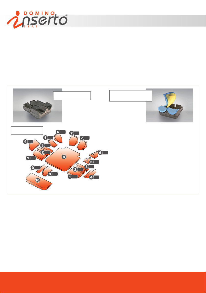
Pic.3 Pre-assembled Kit
+ padding Kit
01) Anterior insert for thighs position
02) Medial anterior insert for thighs position
03) Trapezoidal posterior insert for thighs position
04) Adductor insert
L
05) Medial hip guide insert
06) Pelvis guide insert
07) Buttock guide insert
08) Flat base of construction
09) Abductor insert
10) Leveling insert
Pic. 2 kit of inserts
R
R
R
Pic.1 Pre-assembled
structural kit
R
R
R
R
L
Inserto Domino
17 MODULAR CONFIGURABLE INSERTS
R
L
L
L
L
L
L
The structural kit of Inserto Domino is composed by a at base of construction and numerous inserts that can be
customised, shaped, modied as needed (Pic.1) and (Pic.2). Each element of the structural kit is supplied with
male/female hooks and loops tape that strongly x the inserts to the at base of construction. The preparation of
the pelvis positioning system shape, based on the prescription and the user’s anatomy and morphology, is done
through the detection of measurement and direct trials, therefore it has to be carried out as follows in order to
ensure a proper commissioning.
SUGGESTIONS RELATED TO SOME OPERATIONS
Positioning the gripping Tape
If it is necessary to replace or add the gripping hook and loops tape on one or more inserts of the structural kit,
please use the extra tape supplied in the packaging.
Page
PRODUCT TECHNICAL SHEET
02
Page 3

www.versainserto.com
PRODUCT TECHNICAL SHEET
In order to do so: remove the adhesive lm and stick the tape rmly on the insert to attach. Therefore, check
for the correct placement. If it is correct remove the tape, taking care to heat the adhesive part for few seconds
by using an industrial hot hair dryer at temperature of around 100° (212°F), then reposition the tape denitely.
Be careful not to damage the materials during this operation
Modifying the Structural kit Inserts
The modications of reduction of the inserts by removal of material where necessary, will be implemented by
cutter. If it is necessary to reconstruct the modied component (where the removed material makes it possible)
use an industrial hot air dryer at a temperature of around 100 ° (212°F) to heat and weld together the two parts
to be recomposed.
Be careful not to damage the materials during this operation
1) Accurately detect the measurements of the user and of his wheelchair/mobility device;
2) Remove the cover;
3) Remove the padding;
4) Dispose the position thighs inserts (3,2,1) on the at base of construction (8) in order to match the distance
ischium RH/LH – popliteal cave RH/LH (-2,5 cm. -0.98”) with the length of the seat obtained by the their
combination for both left and right hand sides.The combination of the distribution and direction of the thighs
inserts may be different for the right hand side and the left hand side.
It should be noted that the function of the at base of construction (8) is to provide a supporting base between
the wheelchair / mobility device, as well as the primary structure of the construction kit on which to build or adapt
the positioning system by using, removing or modifying, as necessary and as required by the prescription, all
other inserts supplied with the construction kit.
INDICATIONS FOR THE LENGTH OF THE SEAT
It is possible to reach the desired seat length by operating on the at base of construction only (8) (see point a),
or on the at base of construction and consequently on the set of inserts supplied in the structural kit (see point
b), or on the inserts of the structural kit only (see point c).
a) Flat Base of construction: The at base of construction (8) has its own sizes accordingly to the size of the
positioning system chosen and have posterior notches of 5 cm.(1.96”) wide by 6 cm. (2.36”) deep.
Therefore it is possible to make it slide between the back rest tubes of the wheelchair /mobility device, once it
has been positioned on the cloth of the seat, in order to reduce its depth up to 6 cm. (2.36”).
If the length achieved is not enough and it is preferable to maintain the entire length of the at base or the user
has an irregular morphology and anthropometric measurements (i.e. leg length discrepancy), it is possible to
reduce the effective length of the at base (8) as needed, by removing the portion of exceeding material with a
cutter horizontally along the entire front or a part of it so as to make it asymmetrical.
b) Flat base of construction and consequently the set of inserts supplied:
Having carried out the above operation as necessary, it may be advisable to make a dimensional adjustment
of the depth measurement of the individual inserts supplied with the structural kit by removing the necessary
material using a cutter.If it is necessary to reduce the depth of the buttock guide inserts (7) remove only a
small part of material, horizontally along the posterior surface, in order to avoid affecting the pelvic contour. It is
Page
PRODUCT TECHNICAL SHEET
03
Page 4

www.versainserto.com
PRODUCT TECHNICAL SHEET
suggested to keep the part of material removed, if not damaged, as occasionally, afterwards can be reused to
adapt the device to user’s changes.
Alternatively it can be suitable a placement of the inserts on the at base of construction (8) by removing the
exceeding inserts; alternatively both operations can be adopted.
If it is necessary to increase the useful length of the seat depth for one or both legs, one or both rows of thighs
position inserts (1,2,3) can be placed longitudinally along the at base of construction (8) and leave between
them the necessary distance in order to reach the desired total length. For this purpose, a measurement up to
2,5 cm. (0.98”) longer than the actual length measurement of the at base of construction can also be obtained.
This can be achieved by positioning longitudinally one or both the anterior thigh positioning inserts (1) on the
at base of construction, with their front portion out of it for a maximum of 2,5 cm. (0.98”) and the rear portion
connected to the surface of the at base by a hooked gripping tape.
c) Set of inserts supplied:
It may be appropriate to make a dimensional adjustment of the measurement of depth of the individual inserts
supplied with the structural kit by removing the necessary material using a cutter. If it is necessary to reduce
the depth of the buttock guide inserts (7) ) remove only a small part of material, horizontally along the posterior
surface, in order to avoid affecting the pelvic contour.It is suggested to keep the part of material removed if not
damaged by removal, occasionally, afterwards it may be reuse in order to adapt the device to the modications
made to the user.
Alternatively it can be suitable a placement of the inserts on the at base of construction (8) by removing the
exceeding inserts; alternatively both previous operation can be adopted. If it is necessary to increase the useful
length of the seat depth for one or both legs, one or both rows of thighs accommodation inserts (1,2,3) can be
placed longitudinally along the at base of construction (8) and leave between them the necessary distance in
order to reach the desired total length. For this purpose, a measurement up to 2.5 cm (0.98”) longer than the
actual length measurement of the at base of construction can also be obtained. What above can be achieved
by placing the anterior thighs positioning inserts (1) longitudinally along the at base with the anterior portion out
of it for a max. of 2,5 cm. (0.98”) and the posterior portion attached to the at base through a hooked gripping
tape.
Please be aware that any depth customisation of the kit must be made by considering the harmony
of the support and the compatibility with the wheelchair/mobility device with particular reference to
the variables to the height and inclination of the footplates, depth of the seat cloth, inclination of the
seating plan
5) Dispose the pelvis guide inserts (6) so as to match the width of the pelvis with the width of the seat obtained
by their combination. It is suggested to accomplish this operation by preparing the inserts (6) directly with the
user seated on the structural kit in order to better align the above inserts. During this operation make sure that
the distance between the pelvis guide inserts (6) is increased of 1,5 cm (0,59”) per side with respect to the width
of the user’s pelvis, in order to allow the perfect t when the padding is applied.
It should be noted that the function of the at base of construction (8) is to provide a supporting base between
the wheelchair / mobility device, as well as the primary structure of the construction kit on which to build or adapt
the positioning system by using, removing or modifying, as necessary and as required by the prescription, all
other inserts supplied with the construction kit.
Page
PRODUCT TECHNICAL SHEET
04
Page 5

www.versainserto.com
PRODUCT TECHNICAL SHEET
INDICATIONS FOR THE WIDTH OF THE SEAT
It is possible to reach the desired seat width by operating only on the at base of construction (8) (see point a),
or on the at base of construction and consequently on the inserts of the structural kit (see point b), or on the
inserts of the structural kit only (see point c).
a) Flat base of construction: The at base of construction (8) has its own sizes accordingly to the size of the
positioning system chosen.
In order to insert the base on the cloth of the seat and reach the consequent compatibility with the width of the
wheelchair/mobility system, it is possible to remove a portion of material from the sides of the base up to total 2
cm. (0.78”) by using a cutter.
b) Flat base of construction and consequently the set of inserts supplied:
After having carried out the operation of point a) it may be necessary to make dimensional adjustment of the
width of the individual insert supplied with the structural kit, by removing the necessary material using a cutter.
It is suggested to remove a small portion of material from the outer edges (max. 1 cm. –0.39”) in order to avoid
affecting the concave design (4.5.6) and along the inner edges (9). Regarding the at inserts (1.2.3) perform
this operation along the longitudinal inner edges, for the buttock guide inserts (7) perform the operation along
the inner longitudinal edges.Alternatively it can be suitable the placement of the inserts on the at base of
construction (8) by removing the exceeding inserts; alternatively both previous operation can be adopted.It is
suggested to keep the part of material removed if not damaged by removal, occasionally, afterwards it may be
reused in order to adapt the device to the modications made to the user. If it is necessary to reduce the depth
of the buttock guide inserts (7), remove only a small portion of material in order to avoid affecting the concave
or convex curves. If it is necessary to increase the useful length with respect of all sizes dened for each model,
it is possible to protrude each insert of the structural kit up to 1 cm (0,39”) out of the at base of construction.
c) Set of inserts of the structural kit:
It also may be appropriate to operate a dimensional adjustment of the width of each insert of the structural kit
by removing the necessary material using a cutter. It is suggested to remove a small portion of material along
the outer edges (max. 1 cm. – 0.39”) in order to avoid affecting the concave or convex curves where present
(4.5.6) and along and along the inner edges (9).Regarding the at inserts (1.2.3) perform this operation along
the longitudinal inner edges, for the buttock guide inserts (7) perform the operation along the inner longitudinal
edges. If it is necessary to reduce the depth of the buttock guide inserts (7), remove only a small portion of
material horizontally, in order to avoid affecting the concave or convex curves. It is suggested to keep the part
of material removed if not damaged by removal, occasionally, afterwards it may be reused in order to adapt
the device to the modications made to the user. Alternatively it can be suitable the placement of the inserts on
the at base of construction (8) by removing the exceeding inserts; alternatively both previous operation can
be adopted. If it is necessary to increase the useful length with respect of all sizes dened for each model, it is
possible to protrude each insert of the structural kit up to 1 cm (0,39”) out of the at base of construction.
6) Place the other inserts as necessary
NOTE: The relation of the thrust, levelling and adhesion to the user’s morphology exerted by the
combined and harmonious use of each insert, enables the alignment and the postural compensation,
as well as the distribution of the body loads along all the sitting surface. Use any useful insert among
those supplied in order to achieve the compensation, support and posture correction and the
individual seat most suitable to match the anatomic shapes of the user.
PRODUCT TECHNICAL SHEET
Page
05
Page 6
www.versainserto.com
PRODUCT TECHNICAL SHEET
7) Cover the structural kit with the padding by adjusting it as shown in Pic. 3.
8) Place the cover back onto the structure. There are elastic sides that can be securely positioned by pulling
the drawstring provided.
9) Once the pelvis positioning system has been assembled, have the user to be seated at least for one hour
and verify if the new seat is causing pressure redness on the skin. If this happens it is recommended to adopt
the most suitable interventions in accordance to the specics dened for the user by the professional operator
under his sole responsibility. On a contrary case, instead, proceed with the delivery of the product to the user.
10) It is advisable to keep documentary records of each operation carried out, as well as to provide the user with
any deprived/removed parts which can be useful for after delivery interventions and/or adjustments.
Before to use the product have the professional user to show the procedures for a correct commissioning and
maintenance.
It is strongly recommended to periodically check the skin of the user in order to verify any risk of
redness appearance.
11) When all operations of preparation of the kit to the shape and measures of the user have been accomplished
and the positioning system is ready to be delivered, it is possible to remove the excess of padding from the
edges by using a cutter. Take care to follow the direction of the cut as in the original design.
In relation to the modication, processing and / or adaptation operations carried out on the structural
kit and padding, the upper surface of the cover could result larger compared to the dimensions of the
seating conguration obtained. Take care to spread the surface well when the user is sitting, in order
to avoid wrinkles
2. Maintenance and cleaning
In order to avoid the development of infections, it is recommended to perform a careful cleaning every 2 weeks
and/or, if needed, check the pelvis positioning system in all its parts by avoiding malfunctions. Regarding the
cleaning of the padding, even if there is no direct contact with the skin, it is suggested to use a dump cloth or a
brush with natural bristles and warm water (max 60°C – 140°F), with the addition of a light gentle detergent, by
rubbing in a circular motion. Then rinse with water. Wipe out the excess of water from the padding by using a
dry cloth and dry away from heat sources. Do not expose the padding to the sun rays. Occasionally it can be
also wash in the washing machine, at max 30°C (86°F), by using a light detergent and centrifuge at a low spin.
The drying time is quite long; it is suggested to be equipped of an additional kit of padding.
The removable cover can be washed as it follows:
- Hand wash and then air dry;
- Washing machine (max temperature 60°C – 140°F) with the addition of a gentle detergent, bleach free, then
centrifuge at a low spin.
It is advisable to use a protective wrapping before inserting in the washing machine in order to avoid
any tearing of the lm provided in the cover. It is suggested to be equipped of an additional cover.
Page
PRODUCT TECHNICAL SHEET
06
Page 7
www.versainserto.com
PRODUCT TECHNICAL SHEET
For additional information, please contact our technical-Sales Department at the following number:
+39 0831 777840
INSERTO DOMINO
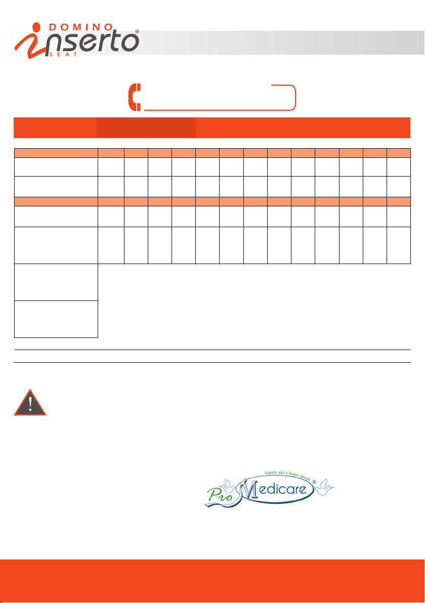
SIZES TABLE
MODEL UUS USS US XXS XS XS1S XS1 S M M1S M1 L XL
Effective width (cm) 25 30 30 36 36 40 40 42 42 45 45 48 48
Max width achieved with
adaptation (cm)
Min. width achieved with
removal of material (cm)
Effective length (cm) 30 30 38 38 42 40 45 45 50 45 50 45 50
Max. length achieved
with adaptation (cm)
Min. length achieved with
adjustment through
seat notches and
removal inserts (cm)*
Min. and max. range of
anterior height of
at base of construction+
insert 1/2/3 (cm)**
Min. and max. range of
posterior height of at
base of construction +
insert 7 (cm)**
Weight of positioning system (min/max): 0,7 kg/2,8 kg
PAEDIATRIC ADULT
27 32 32 38 38 42 42 44 44 47 47 50 50
23 28 28 34 34 38 38 40 40 43 43 46 46
32,5 32,5 40,5 40,5 44,5 42,5 47,5 47,5 52,5 47,5 52,5 47,5 52,5
24 24 32 32 36 34 39 39 44 39 44 39 44
4/5,5 ** height referred to models UUS and XL
8,5/11,5 ** height referred to models UUS and XL
SIZES (cm.)
Max load (referred to model XL 48cm x 50cm): 135 kg
* possible and further reductions due to removal of material
Any operation of removal, preparation or adjustment for the specic user, on the basis of a prescription, have to
be performed by a professional operator and those interventions get the device customised. The professional
user has the charge and the responsibility to guarantee the efcacy and the performances of the device
Labeling
Below it is reported the description of the product as it is shown on the CE Label:
- The complete name of the device is: Seat VERSA INSERTO DOMINO size Xx
- The name of the product shown on the label is: VERSA INSERTO D. size Xx where D stays for Domino
MANUFACTURED BY:
COMPANY CERTIFIED WITH QUALITY MANAGEMENT SYSTEM ISO 9001 / EN ISO 13485 BY BUREAU VERITAS S.P.A.
Via Montagna Z.I. - Lotto 41 72023 Mesagne (BR) - ITALY
Tel. +(39) 0831 777840 - Fax. +(39) 0831 730739 - Email: [email protected]
www.versainserto.com - www.promedicare.eu
PRODUCT TECHNICAL SHEET
SCH.TEC.PRO.INS.SEA.DOM. EN Rev.5 - 04/2018
Page
07
Page 8

www.versainserto.com
INSTRUCTION MANUAL
Via Montagna Z.I. Lotto 41 c.a.p. 72023 Mesagne (BR) - ITALY
Tel . (+39) 0831.777840 - Fax . (+39) 0831.730739
Sito web: www.promedicare.it - e mail: [email protected]
MAN. VER. INS. SEA. EN REV. 5 04/2018
Page 9
Index
1 OPERATING INSTRUCTIONS
1.1 Packing and transportation
1.2 Placing into service
1.3 User instructions
1.4 Processing instructions
2 GENERAL WARNINGS
2.1 User warnings
www.versainserto.com
Pag 04
Pag 04
Pag 05
Pag 06
Pag 07
3 ADVERSE COLLATERAL EFFECTS
4 RESTRICTIONS OF USE
5 ADAPTATIONS WITH STRUCTURAL CHANGES AND/OR
SPECIAL MAINTENANCE
6 PERFORMANCE AND DURABILITY
7 WARRANTY
8 MONITOR OF ANY ACCIDENT AFTER-SALE
The techinical sheet attached is to be intended as an integral
part of the Instruction Manual
ANNEXES
- > Annex 1: Warranty replacements of components /Adaptations with
structural changes and/or special maintenance
- > Annex 2: Monitor of any after-sale accident
Pag 09
Pag 09
Pag 09
Pag 10
Pag 11
Pag 12
INSTRUCTION MANUAL
Page
02
Page 10
www.versainserto.com
Introduction
Thank you for choosing the VERSA pelvis positioning system INSERTO which is a combination of
technology and experience in the development of positioning systems for disabled people.
“Inserto seats” pelvic positioning system, can simply be adapted to the user as needed.
“Inserto seats” pelvic positioning system can also be customised, molded, modified, in order to
be set up and prepared as from prescription to anatomy and morphology of the user through
the detection of its body mesurements, and direct trials so as to obtain a custom seat for the
perfect replication of its anatomic shapes for supporting or compensing its deformities, as well
as the body loads distribution.
The INSERTO range is adaptable to somatic growth and pathological changes. Their composition
makes them very comfortable, achieving optimal comfort with the maximum functionality by
offering high postural solution. The pelvis positioning system Inserto seat can be combined, by means of an adhesive gripping tape, to any supporting base and/or wheelchair
whether manual or powered, provided that the structure will host the positioning system
is solid enough to safely support the user during the use.
This manual is based upon the medical devices requirements of the 93/42/CEE directive.
It is an indispensable instrument for the knowledge of the procedures for safe and correct use
of the device.
All professionals and users are encouraged to carefully read the ‘placing in service instructions’
with the express invitation to strictly follow the indicated procedure.
The initial commissioning operations, subsequent adjustments and special maintenance must be carried out exclusively by
the professional operator.
If an individual custom seat has been prepared and set up as prescribed, it can not be used by other user.
Any operation of removal, preparation or adjustment for the specific user, on the basis of a prescription, have to be performed
by a professional operator and those interventions get the device customised. The professional user has the charge and the
responsibility to guarantee the efficacy and the performances of the device.
The EC declaration of conformity refers only and exclusively to the medical device “as it is” as
prepared by the manufacturer, when it is not modified with respect to the standard configuration.
The EC label is on the last pages of this manual and on the bottom of each medical device.
The features of the device are described in the Technical sheet here attached. After consulting
this manual, for further details, please contact our Customer Service at the following number:
+39 0831 777840 Monday to Friday from 9,00 to 13,00 and from 14,30 to 18,30.
In case of major emergencies out of working hours, please fax to the following number:
+39 0831 730739 We will reply as soon as possible.
Page
INSTRUCTION MANUAL
03
Page 11
www.versainserto.com
For an appropriate after-sale monitoring the device, or in the event of an accident during the
use, please refer to the instructions stated in the relevant chapter.
1 CLINICAL INFORMATION/DESTINATION OF USE
The clinical information of medical device are written in the technical data sheet attached
2 OPERATING INSTRUCTIONS
2.1 Packaging and trasportation
The original package contains the following components :
1) The pelvic positioning system
- a structural kit composed by a flat base/preshaped base of construction and several inserts;
- a kit of padding or a single padding;
- cover.
2) Additional inserts (based upon model);
3) labeling and instruction manual;
4) hooks and loops (velcro) for use on seat bases.
Upon delivery, please check the integrity of the package. Any irregularity must be reported on
the shipping document. Upon opening the package, please check for any damage, dents,
cuts, or lacerations. The presence of one of these conditions must be reported on the shipping
document.
After perfoming the above checks, if the product is not put into immediate use, we recommend
that it is repackaged and stored in a dry place and protected from the bad weather.
The above procedure is the responsibility of the clinical professional or authorised dealer who
will perform the adaptations.
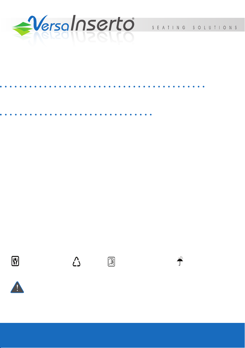
handle with care recycle
reading manual use keep dry
2.2 Placing into service
These operations must be performer by a clinical professional or authorised dealer
For an appropriate assembling of the positioning system, please read the technical sheet of the
product here attached.
Page
INSTRUCTION MANUAL
04
Page 12

www.versainserto.com
2.3 User Instruction
“Inserto seat” positioning system, set up and configured by the professional operator under his
responsibility, in accordance with the characteristics of design defined by the professional operator
for the specific user, is ready for use, after the check of the color of the skin.
If an individual custom seat has been prepared and set up as prescribed, it can not be used by
other user.
Any operation of removal, preparation or adjustment for the specific user, on the basis of a
prescription, have to be performed by a professional operator and those interventions get the
device customised.
The professional user has the charge and the responsibility to guarantee the efficacy and the
performances of the device.
2.3.1 System Transfer
Before starting this operation we strongly reccomend that the user / caregiver is shown the correct
method by a clinical professional / authorised dealer for reducing any possible danger.
when you want to proceed with any trasportation of the positioning system, it is necessary to:
• leave the positioning system in position as it is if the supporting frame is a rigid one, and then
proceed with the transfer.
• remove the positioning system if the supporting frame is foldable. In this case, please proceed in
the following way:
- operate the parking brakes and make sure the wheelchair is locked;
- unfasten any securing components on the positioning system wich could impede the removal;
- take out any kind of hip guides, if they could impede the removal of the positioning system;
- remove the positioning system from the supporting base taking care to preserve the hooks
and loops stripes;
- proceed by folding the wheelchair.
• To replace the seat on the supporting base, please perform as follows:
- unfold the wheelchair;
- operate the parking brakes and make sure the wheelchair is locked;
- position the solid base (if present) on the wheelchair, taking care to verify it is locked;
- position the positioning system on the base, taking care to verify the complete adhesion of the
hook and loops strip of the seat with respect to the support base (check the seat notches and the
label REAR POSTERIOR are positioned in the rear part);
- proceed verifyng all adjustments.
INSTRUCTION MANUAL
Page
05
Page 13
www.versainserto.com
2.4 Processing Instructions
In order to guarantee safe use and a long lasting performance of the pelvis positioning system,
please find below advice for the user and/or caregiver:
• carefully follow all instructions reported in this manual and in the technical sheet of the product;
• carefully follow all directions and advice provided by the clinical professional / authorised dealer;
• keep the positiong system away from heat;
• any unauthorised modifications performed by a non clinical professional or an unauthonsed
dealer, or the use of components not supplied or approved by the producer, can affect the safety
and proper use of the product and could he a cause of danger by the medical device;
• Clean carefully and pay particular attention to the standard maintenance.
In the case of the appeareance of the skin irritation or redness, please stop using the
product and refer to the clinic professional/authorized dealer; should you ear noise,
vibrations or encounter variations during the normal use, please refer to the clinical
professional/authorized dealer in order to verify the safe and suitable conditions of
use and good performances.
INSTRUCTION MANUAL
Page
06
Page 14

www.versainserto.com
3 GENERAL WARNINGS
All warnings reported in this section describe the conditions and situations which may cause
danger to end user. Please read carefully before putting the positioning system into the service.
For an appropriate use of the device some operations, such as the starting and the making of
adjustments, must be done exclusively by an authorised clinical professional or dealer - normal
operations can be performed by the user or by his or her caregiver/attendant
The professional operator is, a person who by virtue of his professional qualification is authorised
by the national law to issue a prescription containing specific characteristics and design for use
addressed to a specific user. On the other hand, the end user is the person who uses the device
or his companion /parent/care giver.
3.1 Warnings for the end user
Before use, have the clinical professional or authorised dealer explain all procedures for correct
commissioning and maintenance. For further information or clarification, please contact a
clinical professional or authorised dealer.
1) Environmental Conditions:
( A ) some components can lose their properties when in direct contact with water or excess
humidity:
• do not use the positioning system in a shower, swimming pool or in locations with the presence
of water or high humidity. This will cause components to deteriorate and malfunction;
• do not take the positioning system in humid places (such as sauna or steamy bathroom after
a shower);
• avoid the contact with sea water;
• if the seat is in contact with water and/or urine or becomes soiled, please clean thoroughly dry
immediately all surfaces and/or covers.
Page
INSTRUCTION MANUAL
07
Page 15

www.versainserto.com
( B ) some environmental conditions may affect the positioning seat system and their functionality
and performance, so, please:
• avoid exposure to extreme temperatures;
• avoid long exposure to direct sunlight.
2) Standard maintenance/cleaning
It is recommended to perform a careful cleaning and a standard maintenance every 2 weeks. It is
also advisable to check all parts of the positioning system in order to avoid malfunctions.
For correct maintenance and cleaning operations, please read carefully the technical sheet of the
product here attached.
INSTRUCTION MANUAL
Page
08
Page 16
www.versainserto.com
4 ADVERSE EFFECTS
The use of the pelvis positioning system does not generate undesired collateral effects, such as
allergies or skin irritations and redness. In a contrary case, it is necessary to refer to a doctor and
to the clinical professional. Daily monitor the skin in contact with the positioning system in order
to make a prompt diagnosis as to any occurrence of any pressure sore caused by an incorrect
or outdated adjustment of the positioning system, in this case, please stop using it and refer to
the clinical professional/authorized dealer.
5 RESTRICTION OF USE
The VERSA range of INSERTO seats has been designed and constructed to provide the end user
the correct positioning support within the normal activities of daily working life, social relations,
school and leisure time. Any other use may jeopardize the system.
6 ADAPTIONS WITH STRUCTURAL CHANGES AND/
OR EXTRAORDINARY MAINTENANCE
In case of breakage or tearing o fan INSERTO component, it is required to replace them with
original parts only supplied by the producer. If the rupture or laceration is limited to the upholstery,
only the material cover will be replaced. Only the strict observance of these requirements will
guarantee the security required by Directive EEC 93/42 and subsequent amendments and
additions. For any extraordinary o special maintenance procedures or repairs, the end user or
the caregiver must refer to the authorized dealer or clinical professional, who will arrange the
return the pertinent component form Annex 1 to the producer within 24 hours from the request
of intervention.
Page
INSTRUCTION MANUAL
09
Page 17
www.versainserto.com
7 PERFORMANCE AND DURABILITY
PRO MEDICARE S.r.l. ensures that its production line “VERSA”, specifically “INSERTO SEAT”
was designed and built in compliance with safety regulations as stated in the relevant
directive 93/42/CEE.
The performances provided by the above-mentioned devices, used individually or in
combination, are suitable and responsive to the design destination aimed to the positioning for
users with mobility limits.
The realistic life spam of the product under normal and safe conditions is 3 years.
This period is purely indicative because the daily use demands are different for all users and will
be significantly influenced by the adherence of regular and correct adjustments, installations
and maintenance schedule. lmproper use and poor maintenance will significantly reduce the
life spam of the product.
It is strongly recommended to check periodically the patient in case of appearance
of redness specially if the use of the positioning system is continuous during the day.
INSTRUCTION MANUAL
Page
10
Page 18

www.versainserto.com
8 WARRANTY
PRO MEDICARE S.r.l. warrants functionality for a maximum period of 24 months, covering all
manufacturing defects from the first use and 12 months on covers and components replaced
under special maintenance from the first date of service installation.
The warranty is valid provided that the device is used as shown in this instruction manual.
The warranty is void in the following cases:
• for misuse and/or force major;
• for failure arising from unauthorised tampering or faulty maintenance caused by third
persons that may affect the correct functionality and the safety of the product;
• modifications made without the producer’s authorization;
• accidental damage of the essential components;
• structural changes of the user not being accounted for by seat modification;
• failure or damage during transportation. The clinical professional/authorised dealer, please
see the general sale conditions in case of damage during the transport;
• robbery or loss.
Regarding any replacement of components under warranty, the user or the caregiver must refer
to the clinical professional/authorised dealer who will arrange return to the producer with the
relevant form Annex 1 within 24 hours after the intervention request.
It is essential for the producer to receive a completed warranty registration form from the
authorized dealer.
Page
INSTRUCTION MANUAL
11
Page 19
www.versainserto.com
9 MONITOR OF
AFTER-SALE INCIDENTS
PRO MEDICARE S.r.l. ensures that their medical device products are produced within strict
compliance with the criteria and requirements established by the relevant National EU rules and
give adequate security of operation in the conditions required by Directive N° 93/42/EEC and
subsequent amendments and additions for after-sale monitoring.
We consider it essential to monitor via after-sale and service, the reliability of our products and
constantly search to improve the quality of our devices. The monitoring of any incident that may
have caused serious physical harm to end users, their caregivers or to a clinical professional/
authorised dealer in connection with the use of any device, we will comply with the safety
standards set by the Directive.
lt follows that, in the case of any incident.
IT IS DULY REQUIRED
to send to the producer a copy of the Annex 2 completed in all its parts.
As soon as PRO MEDICARE S.r.l., receives the above form, we will immediately report to the
appropriate authorised professional all information, as well as an authorisation to repair the
damage device, or its complete replacement.
IN URGENT CASES IT IS DULY RECOMMENDED TO CALL THE PRODUCER
AT THE FOLLOWING NUMBER:
SENDING AS SOON AS POSSIBLE BY FAX THE ANNEX 2 CDULY COMPLETED.
INSTRUCTION MANUAL
+39 0831 777840
Page
12
Page 20
Annex 1
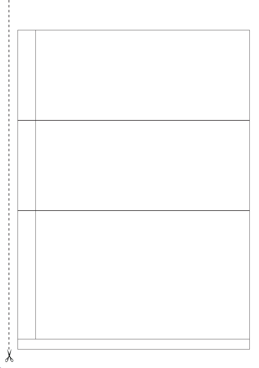
Clinical Professional / Authorised Dealer:_________________________________________
Address:________________________________City:______________________________
State:_______Post Code#:_____________tel:__________________fax:_______________
Base:_____________________________________ Serial #:_________________________
Versa system:__________________________________ Serial #:_____________________
Tecnical information
Order Details: Invoice #_______________________________Date: __________________
Shipping Doc. #:__________________________________ Date: ____________________
Malfunction: ________________________________________________________________
___________________________________________________________________________
_________________________________________________________________________
Component to replace : ____________________________________Quantity: ___________
Note:_____________________________________________________________________
_________________________________________________________________________
1. Replacement under warranty
Cause of Intervention: _______________________________________________________
________________________________________________________________________
Component to replace: _______________________________________________________
Related to: ________________________________________
Quantity:__________
Note
(in case of maintenance please specify if the failure of the components is total or partial) :______________
_____________________________________________________________________________________
and/or special maintenance
2. Adaptation with structural changes
N.B. All unauthorized written interventions will void the CE mark
To be sent to the producer within 24 hours after the request of intervention to the fax +39 – 0831 - 730739
Page 21

Page 22
Annex 2 - Monitor of any after-sale incidents
Clinical Professional / Authorised Dealer:_________________________________________________
Address:________________________________City:______________________________________
State:_______Post Code#:_____________tel:__________________fax:_______________________
Base:_____________________________________ Serial #:________________________________
Versa system:__________________________________ Serial #:____________________________
Order Details: Invoice #_______________________________Date: _________________________
Shipping Doc. #:__________________________________ Date: ____________________________
Date of incident: ___________________________________________________________________
Description of incident: ______________________________________________________________
__________________________________________________________________________________
Causes (accidental, collision, not correct operation, structural failure, etc.)______________________
_________________________________________________________________________________
Component: ______________________________________________________________________
Related to the following part : ______________________________________ Quantity:___________
Severe injuries: ____________________________________________________________________
Rapair in safety conditions: O No
O Yes (continue to ll in the form)
Component to be replaced:___________________________________________________________
Related to the following part: ____________________________________Quantity:______________
Note:____________________________________________________________________________
_________________________________________________________________________________
_________________________________________________________________________________
To be sent immediately to the producer at the following fax: +39 - 0831. 730739
Page 23

COMPANY CERTIFIED WITH QUALITY MANAGEMENT SYSTEM ISO 9001 / EN ISO 13485 BY BUREAU VERITAS S.P.A.
 Loading...