

Page 1
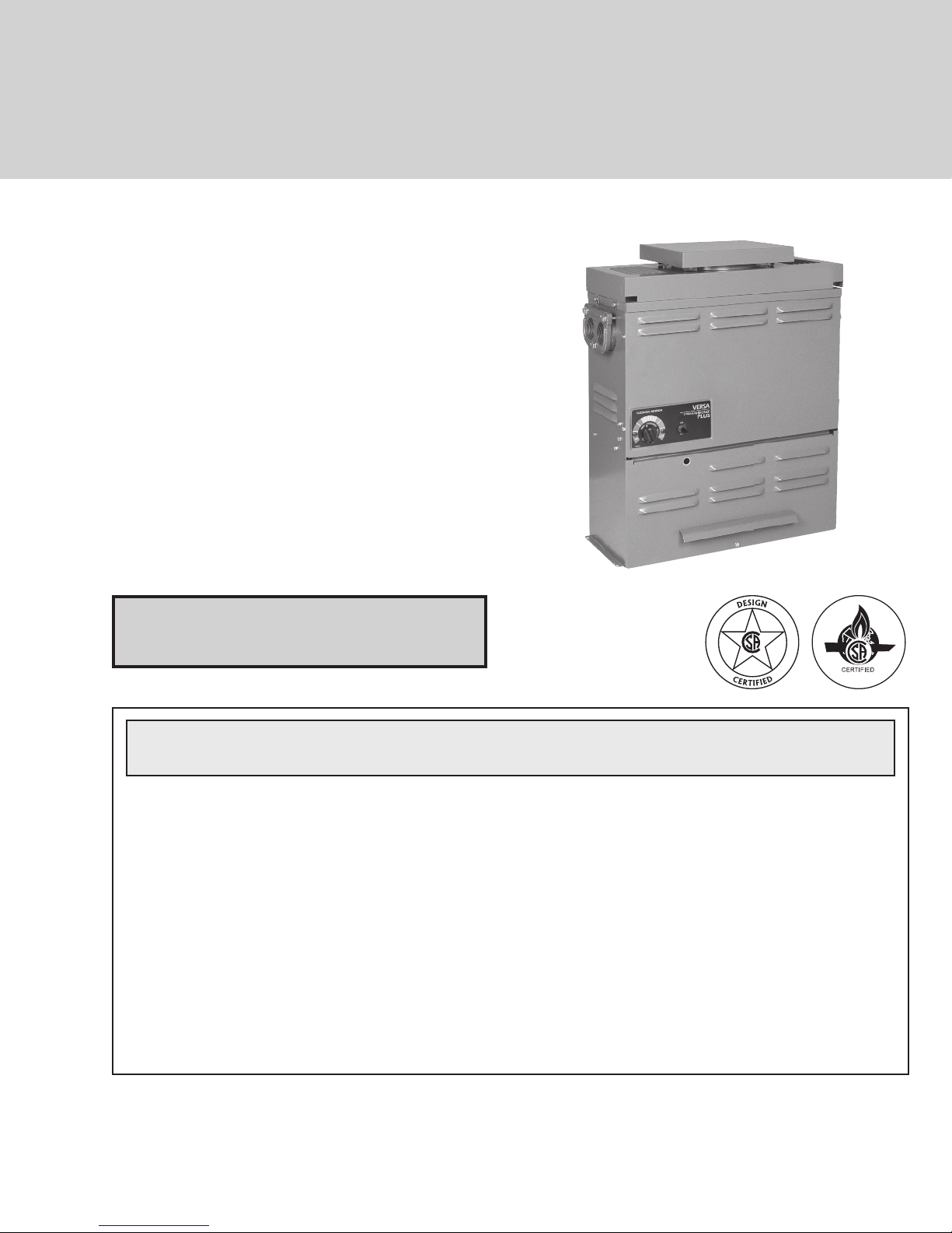
INSTALLATION & OPERATING
INSTRUCTIONS
Versa™
Spa
Heater
Model 055B
WARNING: If the information in these instructions are not followed exactly, a fire or
explosion may result causing property damage, personal injury or death
FOR YOUR SAFETY: Do not store or use gasoline or other flammable vapors and
liquids or other combustible materials in the vicinity of this or any other appliance. To
do so may result in an explosion or fire.
WHAT TO DO IF YOU SMELL GAS:
• Do not t
• Do not touch any electrical switch; do not use any phone in your building.
• Immediately call your gas supplier from a neighbor's phone. Follow the gas
supplier's instructions.
• If you cannot reach your gas supplier, call the fire department.
Installation and service must be performed by a qualified installer, service agency or
the gas supplier.
o light any appliance.
ry t
.
This manual should be maintained in legible condition and kept adjacent to the heater or in another safe place for
future reference.
CATALOG NO. 6100.52W Effective: 05-23-11 Replaces: 01-21-10 P/N 240428 Rev. 24
Page 2

Rev. 24 reflects the following:
Changes to: Water Chemistry (Table A) on page 5, Wiring Diagram on page 20.
2
Page 3

CONTENTS
WARNINGS 4
Pay Attention to These Terms 4
WATER CHEMISTRY 5
OWNER'S OPERATING INSTRUCTIONS 6
Start-Up Procedures 6
Water Temperature Safety 9
MAINTENANCE AND CARE PROCEDURES 9
Basic Tips if Heater Will Not Fire 9
Pool & Spa Water
Chemistry 10
Cold Weather Operation 10
Winterizing the Spa Heater 10
INTRODUCTION 10
Receiving Equipment 10
General Specifications 11
INSTALLATION 11
Code Requirements 11
Base Installation 11
Clearances 11
Outdoor Heaters 13
Indoor Heaters 13
Combustion Air
(Indoor Units Only) 13
Vent Piping 14
Vent Terminal Assembly 14
Gas Supply Connections 15
Plumbing for Water Connections 16
Electrical Wiring 18
Wiring Diagram—Millivolt Units with
Mechanical Thermostat 20
Wiring Diagram—IID Units 21
SERVICE 22
Controls/Adjustments/
Replacements 22
TROUBLESHOOTING 27
REPLACEMENT PARTS LIST 31
3
Page 4
WARNINGS - Pay Attention to These Terms
DANGER:
WARNING:
CAUTION:
NOTE:
WARNING: To minimize the possibility of improper
operation, serious personal injury, fire, or damage to
the heater:
• Always keep the area around the heater free of
combustible materials, gasoline, and other
flammable liquids and vapors.
• Heater should never be covered or have any
blockage to the flow of fresh air to the heater.
WARNING: Improper installation, adjustment,
alteration, service, or maintenance can cause
property damage, personal injury or loss of life.
Refer to the user's information manual provided with
this heater. Installation and service must be
performed by a qualified installer, service agency, or
the gas supplier.
WARNING: Gasoline, as well as other flammable
materials and liquids (adhesives, solvents, etc.), and
the vapors they produce, are extremely dangerous.
Do not handle, use, or store gasoline or other
flammable or combustible materials in the vicinity of
a heater.
Indicates the presence of immediate hazards which will cause severe
personal injury, death or substantial property damage if ignored.
Indicates the presence of hazards or unsafe practices which could cause
severe personal injury, death or substantial property damage if ignored.
Indicates the presence of hazards or unsafe practices which could cause
minor personal injury or product or property damage if ignored.
Indicates special instructions on installation, operation, or maintenance which
are important but not related to personal injury hazards.
WARNING: This unit contains refractory ceramic
fiber (RCF) insulation in the combustion chamber.
RCF, as manufactured, does not contain respirable
crystalline silica. However, following sustained
exposure to very high temperatures (>2192F), the
RCF can transform into crystalline silica
(cristabolite). The International Agency for Research
on Cancer (IARC) has classified the inhalation of
crystalline silica (cristabolite) as carcinogenic to
h
umans.
When removing the burners or heat exchangers,
take precautions to avoid creating airborne dust and
avoid inhaling airborne fibers. When cleaning spills,
use wet sweeping or High Efficiency Particulate Air
(HEPA) filtered vacuum to minimize airborne dust.
Use feasible engineering controls such as local
exhaust ventilation or dust collecting systems to
minimize airborne d
protective equipment including gloves, safety
glasses with side shields, and appropriate NIOSH
certified respiratory protection, to avoid inhalation of
airborne dust and airborne fiber particles.
CAUTION: Verify proper operation after servicing.
ust. Wear appropriate personal
WARNING - CALIFORNIA PROPOSITION
65: This product contains chemicals known to the
State of California to cause cancer, birth defects or
other reproductive harm.
NOTE: Minimum 18 AWG, 105°C, stranded wire
must be used for all low voltage (less than 30 volts)
external connections to the unit. Solid conductors
should not be used because they can cause
excessive tension on contact points. Install conduit
as appropriate. All high voltage wires must be the
same size (105°C, stranded wire) as the ones on the
unit or larger.
4
Page 5
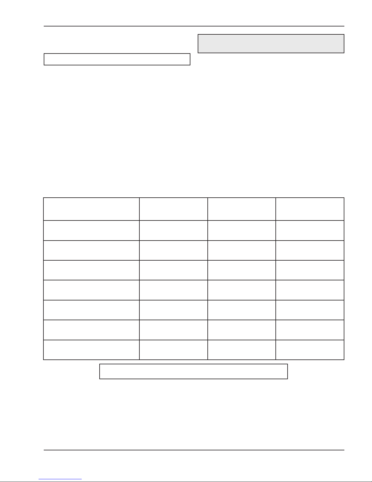
WATER CHEMISTRY
CAUTION: Free chlorine must not exceed 5 ppm
which can damage the heater and void the warranty.
NOTE: Corrosive water voids all warranties.
Chemical imbalance can cause severe damage to
your heater and associated equipment. Maintain your
water chemistry according to Table A. If the mineral
content and dissolved solids in the water become too
high, scale forms inside the heat exchanger tubes,
reducing heater efficiency and damaging the heater. If
the pH drops below 7.2, this will cause corrosion of the
heat exchanger and severely d
exchanger damage resulting from chemical imbalance
is not covered by the warranty.
For your health and the protection of your pool equipment, it is essential that your water be chemically
balanced. The following levels must be used as a
guide for balanced water.
amage the heater. Heat
Recommended Level(s) Fiberglass Pools Fiberglass Spas
• Occasional chemical shock dosing of the pool or
spa water should not damage the heater providing
the water is balanced.
• Automatic chemical dosing devices and salt chlorinators are usually more efficient in heated water,
unless controlled, they can lead to excessive chlorine level which can damage your heater.
• Further advice should be obtained from your pool
or spa builder, accredited pool shop, or c
supplier for the correct levels for your water.
Other Pool & Spa
Types
Water Temp. (Deg. F) 68 to 88 89 to 104 68 to 104
hemical
pH 7.3 to 7.4 7.3 to 7.4 7.6 to 7.8
Total Alkalinity (PPM) 120 to 150 120 to 150 80 to 120
Calcium Hardness (PPM) 200 to 300 150 to 200 200 to 400
Salt (PPM) 4500 MAXIMUM 4500 MAXIMUM 4500 MAXIMUM
Free Chlorine (PPM)* 2 to 3 2 to 3 2 to 3
Total Dissolved Solids (PPM) 3000 MAXIMUM** 3000 MAXIMUM** 3000 MAXIMUM**
* Free Chlorine MUST NOT EXCEED 5 PPM!
** In salt water chlorinated pools, the total TDS can be as high as 6000 ppm.
Table A: Water Chemistry
5
Page 6
OWNER'S OPERATING
After Start-Up
INSTRUCTIONS
WARNING: If you do not follow these instructions
exactly, a fire or explosion may result, causing
property damage, personal injury or loss of life.
Start-Up Procedures
Before Start-Up
Burners
Clean main burners and air louvers of dust, lint and
debris. Keep heater area clear and free from combustibles, flammable liquids and chemicals. Do not
obstruct the flow of combustion and ventilation air.
Water
First thing, ensure that system is filled with water and
have pump operating. Water must be flowing through
the heater durin
peration.
g o
Feel the inlet and outlet pipes. Outlet pipe should be
only slightly warmer than the inlet. It should not be hot.
WARNING: Should overheating occur or the gas
supply fail to shut off, turn off the manual gas control
to the appliance.
Visual Inspection
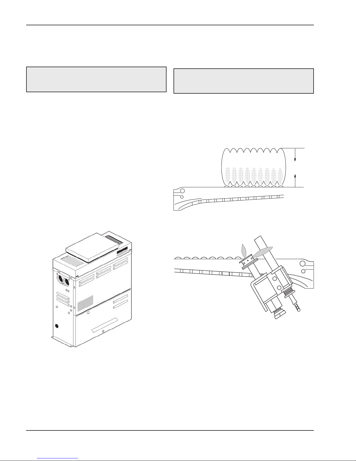
With the heater on, remove the door and make a visual check of the pilot and burner. The flame should be
blue with a well-defined pattern.
4“ MAX
Fig. 2: Correct Main Burner Flame Pattern
Fig. 1: Versa Heater
Fig. 3: Millivolt Pilot Burner Flame
A yellow or "floating" flame indicates restricted air
openings or incorrect orifice size. Should this occur,
shut the heater o
supplier.
Water Pressure Switch
A water pressure switch is provided in the heater to
shut-off the burners in the event that water supply to
the heater is interrupted. It is very important to verify
that the switch electrically opens and shuts off the gas
6
ff and contact your installer or gas
Page 7
CAUTION: Propane is heavier than air and will settle on the ground. Since propane can accumulate in
confined areas, extra care should be exercised when lighting propane heaters.
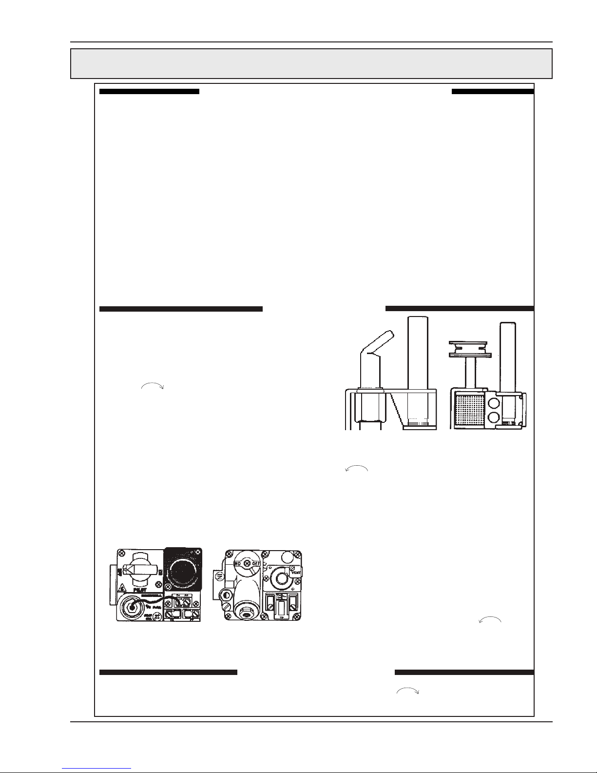
LIGHTING INSTRUCTIONS AND SHUT-OFF PROCEDURES
MANUALLY LIGHTED PILOTS
(MILLIVOLT SYSTEM)
A. This appliance has a pilot that must be lighted by
hand. When lighting the pilot, follow these
instructions exactly.
B. BEFORE LIGHTING smell all around the appli-
ance area for gas. Be sure to smell next to the
floor because some gas is heavier than air and
will settle on the floor.
*If you cannot reach your gas supplier, call the
fire department.
C. Use only your hand to push in or turn the gas
control knob. Never use tools. If the knob will not
push in or turn by hand, do not try to repair it. Call
a qualified service technician. Force or attempted
repair may result in a fire or explosion.
WHAT TO DO IF YOU SMELL GAS:
*Do not try to light any appliance.
*Do not touch any electric switch; do not use any
phone in your building.
*Immediately call your gas supplier from a neigh bor's phone. Follow the gas supplier's instruc tions.
LIGHTING INSTRUCTIONS
1. STOP! Read the safety information above.
2. Set the thermostat on the lowest setting.
3. Turn On-off switch to the "Off" position.
4. Remove heater door panel.
5. Push in gas control knob slightly and turn clockwise to "Off".
NOTE: Knob cannot be turned from "Pilot" to
"Off" unless knob is pushed in slightly. Do not
force.
6. Wait 5 minutes to clear out any gas. If you then
smell gas, STOP! Follow "B" in the safety
information above. If you don't smell gas, go to
the next step.
7. Locate pilot mounted on the left side of the
burner tray. For burner tray location,
see General Location of Controls section,
page 17.
Gas control knobs shown in "Off" position
HONEYWELL
GAS VALVE
MILLIVOLT
ROBERTSHAW
GAS VALVE
MILLIVOLT
D. Do not use this appliance if any part has been
under water. Immediately call a qualified service
technician to inspect the appliance and to replace any part of the control system and any gas
control which has been under water.
ROBERTSHAW PILOT
HONEYWELL PILOT
8. Turn knob on gas control counter-clockwise
to "Pilot".
9. Push in control knob all the way and hold in.
Immediately place flame to pilot to light.
Continue to hold control knob in for about 1
minute after the pilot is lighted, release knob
and it will pop back up. Pilot should remain
lighted. If it goes out, repeat steps 5 through 9.
*If knob does not pop up when released, stop
and immediately call your service technician
or gas supplier.
*If the pilot does not stay lit after several tries,
turn the gas control knob to "Off" and call your
service technician or gas supplier.
10. Stand to the side of the heater and turn the gas
control knob counter-clockwise to "On".
11. Replace heater door panel.
12. Turn On-off switch to the "On" position.
13. Set thermostat to the desired setting.
1. Set the thermostat to the lowest setting.
2. Turn On-off switch to the "Off" position.
3. Remove heater door panel.
TO TURN OFF GAS TO APPLIANCE
4. Push the gas control knob slightly and turn
clockwise to "Off". Do not force.
5. Replace heater door panel.
7
Page 8
CAUTION: Propane is heavier than air and will settle on the ground. Since propane can accumulate in
confined areas, extra care should be exercised when lighting propane heaters.
OPERATING INSTRUCTIONS AND SHUT-OFF PROCEDURES
AUTOMATICALLY LIGHTED PILOTS
(ELECTRONIC IGNITION SYSTEMS)
A. This appliance is equipped with an ignition
device which automatically lights the pilot. Do
not try to light the pilot by hand.
B. BEFORE OPERATING, smell all around the
appliance area for gas. Be sure to smell next
to the floor because some gas is heavier than
air and will settle on the floor.
WHAT TO DO IF YOU SMELL GAS:
*Do not try to light any appliance.
*Do not touch any electric switch; do not use
any phone in your building.
*Immediately call your gas supplier from a
neighbor's phone. Follow the gas supplier's
instructions.
OPERATING INSTRUCTIONS
1. STOP! Read the safety information above.
2. Set the thermostat to the lowest setting.
3. Turn off all electric power to the appliance.
4. This appliance is equipped with an ignition
device which automatically lights the pilot. Do
not try to light the pilot by hand.
5. Remove heater door panel.
6. Push in gas control knob slightly and turn clockwise to "Off".
Knob cannot be turned to "Off" unless it is
pushed in slightly. Do not force.
7. Wait 5 minutes to clear out any gas. If you then
smell gas, STOP! Follow "B" in the safety information previously stated. If you don't smell gas,
go to the next step.
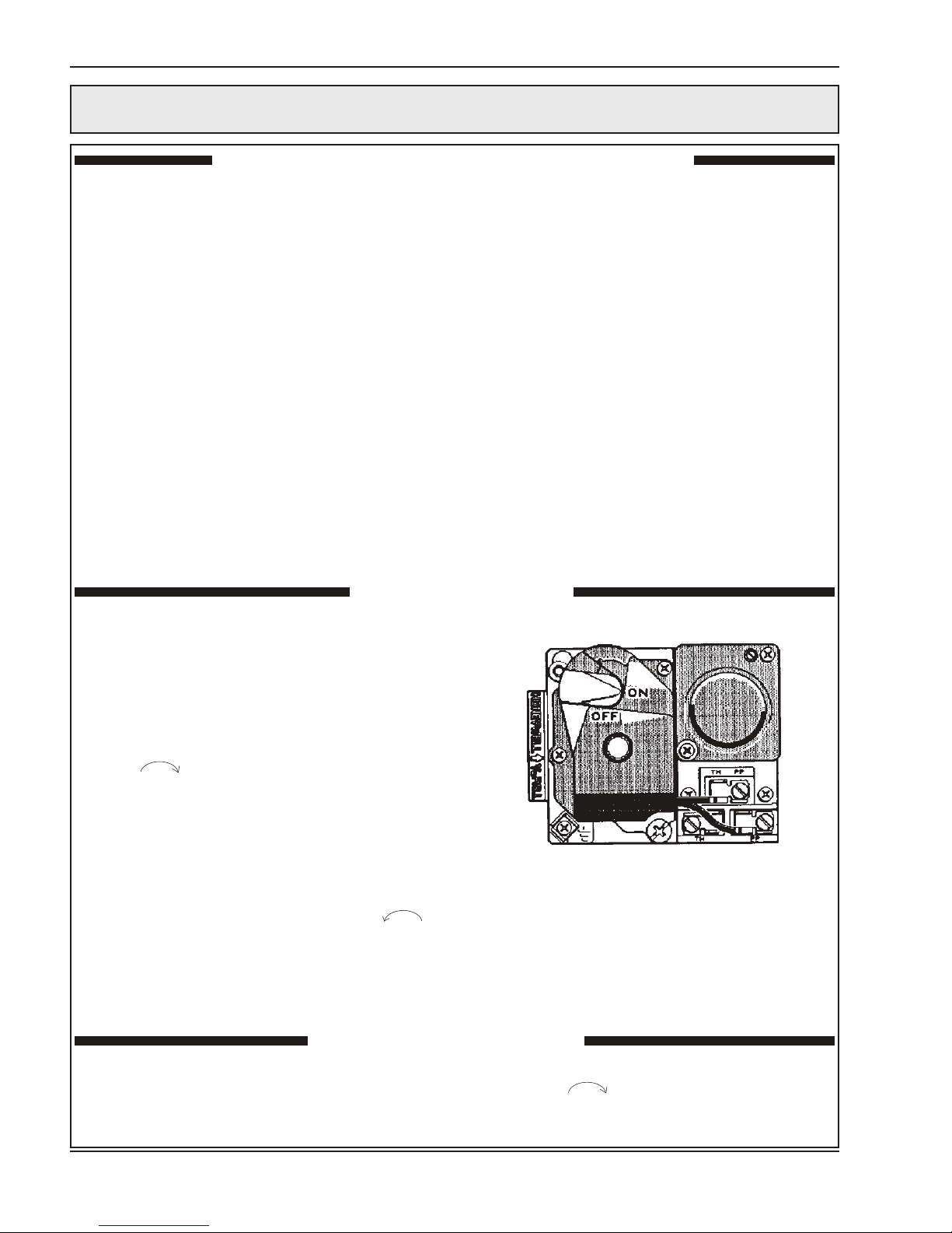
Gas control lever shown in the "On" position.
8. Turn gas control knob counter-clockwise
to "On".
*If you cannot reach your gas supplier, call the
fire department.
C. Use only your hand to push in or turn the
gas control knob. Never use tools. If the
knob will not push in or turn by hand, do not try
to repair it; call a qualified service technician.
Force or attempted repair may result in fire or
explosion.
D. Do not use this appliance if any part has been
under water. Immediately call a qualified service
technician to inspect the appliance and to replace any part of the control system and any gas
control which has been under water.
Gas control knob shown in "ON" position.
GAS VALVE-IID
9. Replace heater door panel.
10. Turn on all electrical power to appliance.
11. Set thermostat to desired setting.
12. If the appliance will not operate, follow the
instructions "To Turn Off Gas To Appliance" and
call your service technician or gas supplier.
TO TURN OFF GAS TO APPLIANCE
1. Set the thermostat at the lowest setting.
2. Turn off all the electric power to the appliance if
service is to be performed.
3. Remove heater door panel.
4. Push in gas control knob slightly and turn
clockwise to "Off".
5. Replace heater door panel.
8
Page 9
valve when water flow to the heater is interrupted.
Otherwise, rapid and severe heater damage will likely
occur. (The water pressure switch should be checked
and adjusted for proper operation by a qualified service person at the time of installation and periodically
checked thereafter. Refer to pressure switch servicing
instructions in this manual.)
WARNING: Operation of the heater without water
circulation will cause rapid and severe damage to
the heater.
Water Temperature Safety
MAINTENANCE AND
CARE PROCEDURES
To be followed one month after start-up and then semiannually.
1. Inspect top of heater and drafthood for soot, a
sticky black substance found around finned tubes,
baffle and open flue gas passageways.
CAUTION: Soot may be combustible. Wet sooted
surfaces completely prior to cleaning. Do not use
steel wire brush.
Elevated water temperature can be hazardous, and
the U.S. Consumer Product Safety Commission recommends the following guidelines:
1. Spa or hot tub water temperatures should never
exceed 104°F (40°C). A temperature of 100°F
(38°C) is considered safe for a healthy adult.
Special caution is suggested for young children.
2. Use of drugs and/or alcoholic beverages before or
during spa or hot tub use may cause drowsiness
which could lead t
quently result in drowning.
3. Pregnant women beware! Soaking in water over
102° F (39°C) may cause fetal damage during the
first three months of pregnancy, including brain
damage or deformity. Pregnant women should
observe the 100°F (38°C) maximum rule.
4. Before entering the spa or hot tub, users should
check the water temperature with an accurate
thermometer; spa or hot tub t
in regulating water temperatures by as much as ±
4 °F (2.2°C).
5. Persons with a medical history of heart disease,
circulatory problems, diabetes, or blood pressure
problems should obtain a physician's advice
before using pools or hot tubs.
6. Persons taking medications which induce drowsi-
ness, such as tranquilizers, antihistamines, or
anticoagulants, should not use spas or hot tubs.
o unconsciousness and subse-
hermostats may err
2. Clean main burners and pilot burner of dust and
lint.
3. Inspect and operate all controls, gas valve and
pressure relief valve.
4. Make visual check of the burner and pilot f
Flame pattern on the main burner and pilot is indicated in the previous illustration. Yellow flame
means restriction of the air openings. Lifting or
blowing flame indicates high gas pressure. Low
flame means low gas pressure. Should this occur,
shut the heater off and contact your gas supplier
or qualified service agency.
5. On indoor heaters, clean room intake openings to
ensure adequate flow of c
tion air.
CAUTION: Combustion air must not be
contaminated by corrosive chemical fumes which
can damage the heater and void the warranty.
6. Keep area around heater clear and free from combustible materials and other flammable and
corrosive vapors and liquids.
ombustion and ventila-
lame.
Basic Tips if Heater Will Not
Fire
If you have no electrical power:
1. The "circuit breakers" may have tripped. Try resetting them.
9
Page 10

If you have electrical power, check the following:
1. The time clock must be moved to the "ON" position.
2. Your pump strainer basket may be full. If so
remove debris.
water below 50°F can seriously damage the heater,
and will void the warranty.
For cold climate areas please follow the winterizing
procedures listed below.
Winterizing the Spa Heater
3. Your filter may be dirty. If so, backwash or clean filter. (If your filter is dirty, the gauge pressure will be
higher than usual).
4. The pump may have lost its prime and be running
dry. Check the pressure gauge on the filter. If there
s no pressure; the water is not moving (or your
i
gauge is broken). Try to get the pump to run at its
normal flow rate.
Pool & Spa Water
Chemistry
Chemical imbalance can cause severe damage to
your heater and associated equipment. Maintain your
water chemistry according to the chart on page 5. If
the mineral content and dissolved solids in the water
become too high, scale forms inside the heat
exchanger tubes, r
damaging the heater.
If the pH drops below 7.2, the heater will be severely
damaged. This will result in corrosion of the heat
exchanger. Heat exchanger damage resulting from
chemical imbalance is not covered by the warranty.
educing heater efficiency and also
Cold Weather Operation
When heaters installed outdoors in freezing climate
areas are to be shut down for the winter, observe the
following procedure:
1. Turn off gas valve, manual gas valve, and electrical supply to the heater.
2. Open drain cock located o
3. Disconnect compression fittings from the pressure
switch and header that connect to the 1/4" copper
tube and allow the tube to drain.
n the return header.
INTRODUCTION
Receiving Equipment
On receipt of your equipment it is suggested that you
visually check for external damage to the carton. If the
carton is damaged, a note should be made on the Bill
of Lading when signing for the equipment. Remove
he heater from the carton and if it is damaged, report
t
the damage to the carrier immediately.
On occasion, we ship some items loose. Be sure that
you receive the number of packages indicated on the
Bill of Lading.
Heater operation can continue during short term cold
spells. When temperatures are below freezing, flow
(continuous pump operation) must be maintained.
CAUTION: Do not use the heater to maintain water
temperatures just above freezing, or for freeze
protection. When heaters are used during freezing
weather, care must be taken to avoid freeze-ups.
Continuous pump operation is a must. Additional
protection may be required. The heater is not
warranted against freeze-ups.
Prolonged operation with water temperatures below
50°F is not recommended. When starting the heater
with pool temperatures below 50°F, operate the heater
continuously until higher temperatures are reached.
Operating the heater for prolonged periods with pool
When ordering parts, you must specify model and
serial number of heater. When ordering under warranty conditions, you must also specify the date of
installation.
The manufacturer recommends that t
reviewed thoroughly before installing your pool/spa
heater. If there are any questions that this manual
does not answer, please contact the factory or your
local representative.
10
his manual be
Page 11

General Specifications
These heaters are design certified and tested under
the requirements of ANSI Z21.56/CSA 4.7 American
National Standard / CSA standards for gas-fired pool
heaters.
WARNING: Improper installation, adjustment,
alteration, service or maintenance may damage the
equipment, create a hazard resulting in
asphyxiation, explosion or fire, and will void the
warranty.
The heater is interchangeable and can be used either
indoors or outdoors. The appropriate top designated
for that type of use is required. If desired, the top can
be changed at a later date to change from outdoor to
indoor o
generating electrical system operating between .25
and .75 volts.
r vice versa. Millivolt heaters contain a self-
Ambient Temperature Rating of
Heater Components
Millivolt Heater with Honeywell Gas Valve
+32°F to +175°F
Millivolt Heater with Robertshaw Gas Valve
0°F to +175°F
Electronic Ignition Heaters*
-32°F to +175°F
*Requires 120V or 240V power supply
Rated inputs are suitable for up to 2000 feet elevation.
or elevations above 2000 feet, reduce input 4% for
F
each 1000 feet above sea level, as high elevation
reduces combustion performance. For Canada,
reduce input 10% when installed at 2000-4500 feet
elevation.
INSTALLATION
NOTE: These instructions are intended for use by
qualified personnel only, specifically trained and
experienced in the installation of this type of heating
equipment and related system components.
Installation and service personnel may be required
by some states to be licensed.
Code Requirements
NOTE: The heater should not be located in an area
where possible water leakage will result in damage
to the area adjacent to the appliance or to the
structure. When such locations cannot be avoided, it
is recommended that a suitable drain pan,
adequately drained, be installed under the
appliance. The pan must not restrict combustion air
flow.
Installation must be in accordance with local codes, or,
in the absence of local codes, with the latest editions
of the National Fuel Gas Code, ANSI Z223.1, and the
National Electrical Code, ANSI/NFPA 70; for Canada,
the latest edition of CAN/CGA B-149.
Base Installation
Heater must be mounted on a level surface. It can be
installed on combustible flooring. Heaters may not be
installed on carpeting.
Clearances
WARNING: The heater shall not be located in an
area where water sprinklers, or other devices, may
cause water to spray through the cabinet louvers
and into the heater. This could cause heavy internal
rusting or damage some electrical components, and
this would void the warranty.
If your state is such, be sure your contractor bears the
appropriate license. Persons not qualified shall not
attempt to fix this equipment nor attempt repairs
according to these instructions.
11
Page 12
Indoor Installation
U.S. Installation Only
Outdoor Installation
Heater Side
Min. Clearance from
Combustible Surfaces
Top* (Drafthood) 35”
Vent 6”
Back 2”
Right Side 6”
Left Side 6”
Floor 0
*Clearance from Top of Vent Terminal
Table B: Clearances from Combustible Construction
For servicing, provide at least 24" in front of the heater
for burner tray removal, and at least 18" on the left side
of the heater to inspect and de-lime the heat exchanger.
Heater Side
Min. Clearance from
Combustible Surfaces
Top* (Stackless Top) Unobstructed
Back 2”
Right Side 6”
Left Side 6”
*Clearance from Top of Vent Terminal
Table C: Clearances from Combustible Construction
For servicing, provide at least 24" in front of the heater
for burner tray removal, and at least 18" on the left side
of the heater to inspect and de-lime the heat exchanger.
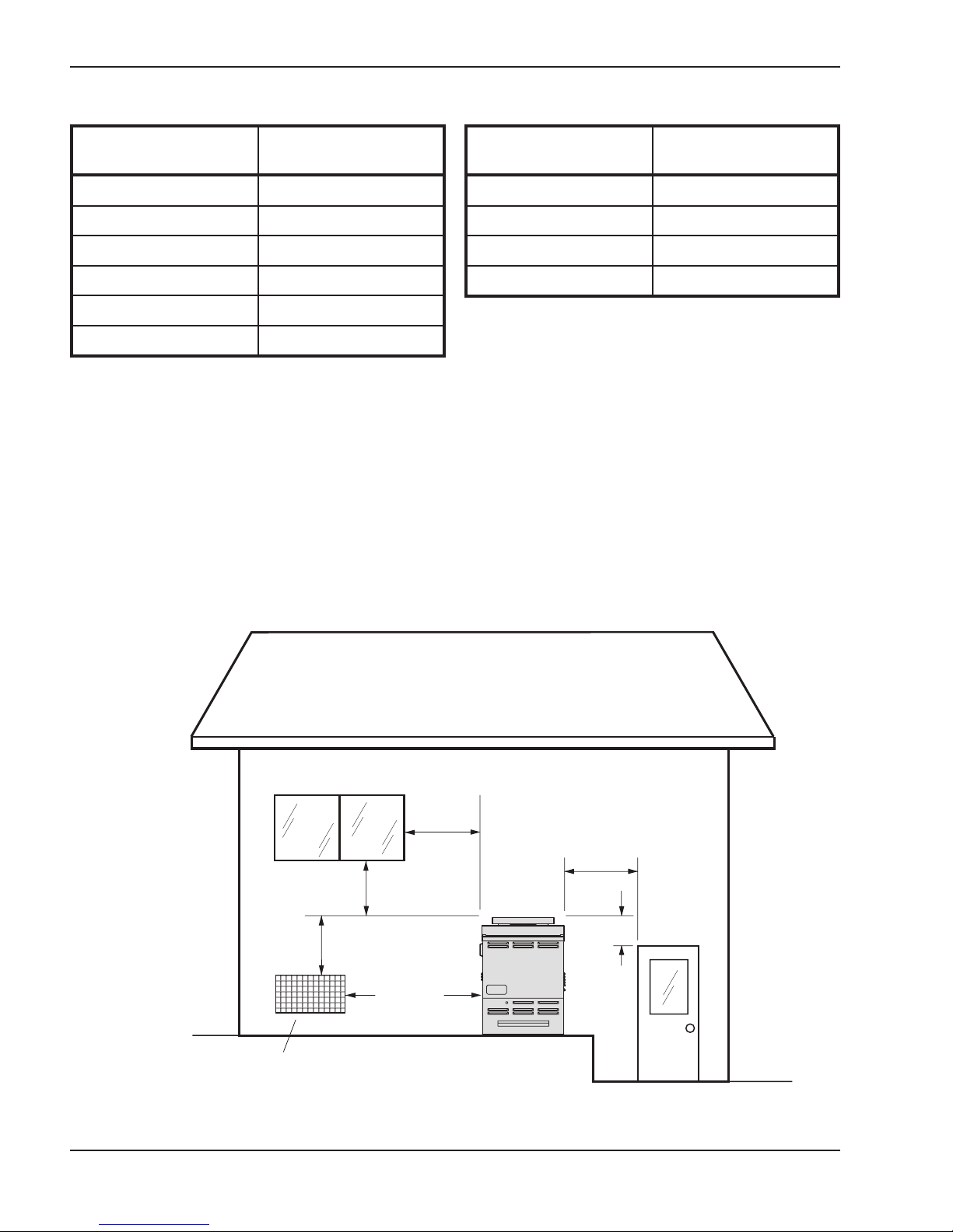
Heaters must not be installed under an overhang of
less than three (3) feet from the top of the heater.
Three (3) sides must be open in the area under the
overhang. Roof water drainage must be diverted away
he heaters installed under overhangs with the
from t
use of gutters. For U.S. installations, the point from
where the flue products exit the heater must be a minimum of four (4) feet below, four (4) feet horizontally
Minimum
3 foot
Minimum
Forced Air Inlet
4 foot
4 foot
Minimum
10 foot
Minimum
Fig. 4: Outdoor Installation
12
4 foot
Minimum
1 foot
Minimum
Page 13
from or one (1) foot above any door, window or gravity inlet to a building. The top surface of the heater shall
be at least three (3) feet above any forced air inlet, or
intake ducts located within ten (10) feet horizontally.
For installations in Canada, pool heaters shall not be
installed with the top of the vent assembly within 10
feet below, or to either side, of any opening into the
building. Refer to t
B149.
he latest revision of CAN/CGA-
Outdoor Heaters
Indoor Heaters
The design is also certified for indoor installation when
equipped with the approved drafthood. For Canada,
indoor installation is restricted to an enclosure that is
not occupied and does not directly communicate with
occupied area. Refer to the latest edition of CAN/ CGA
B-149 for specific requirements.Locate heater as close
as practical to a chimney or gas vent. Heater must
always be vented t
tion for venting details. Minimum clearances are
shown on the nameplate.
o the outside. See Vent Piping sec-
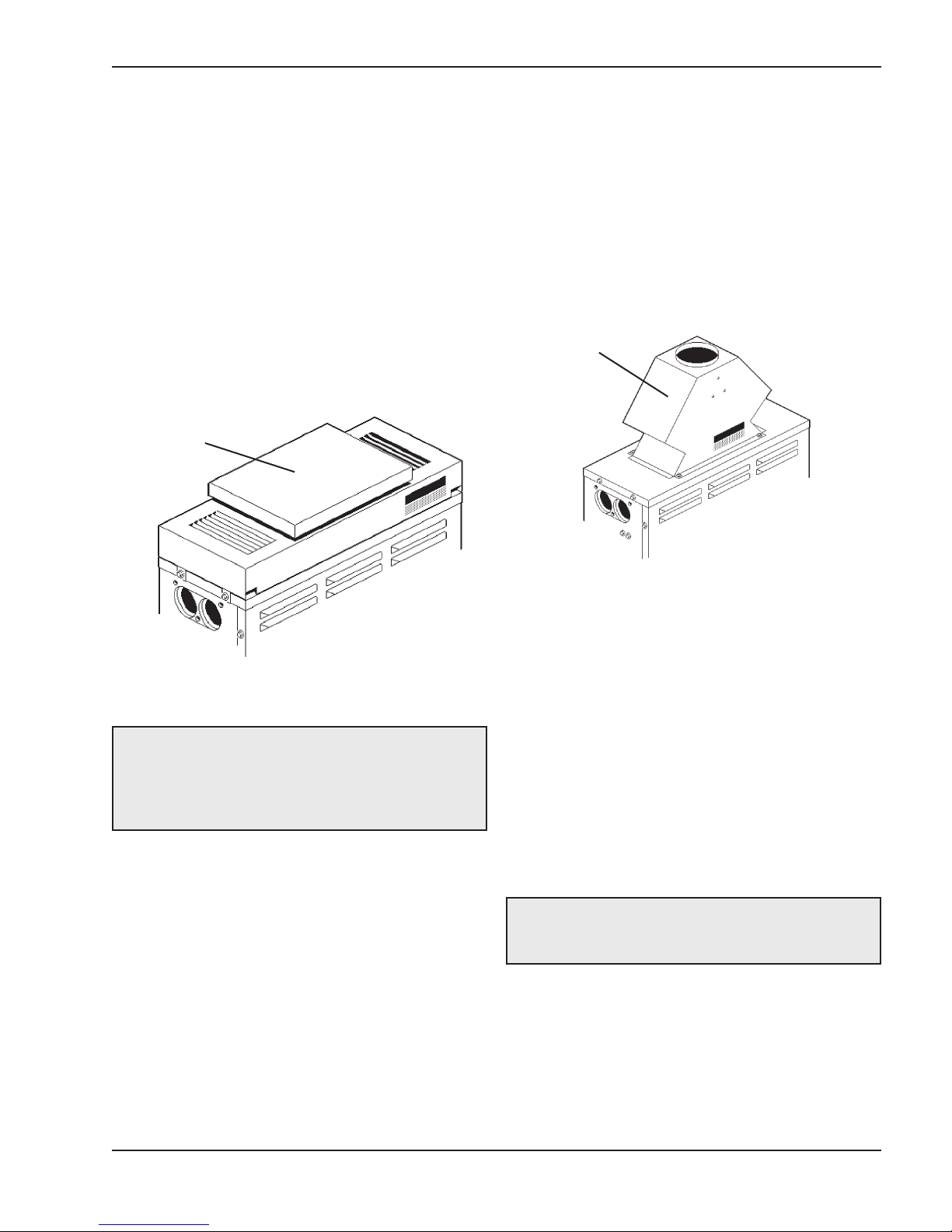
These heaters are design certified for outdoor installation, when equipped with the approved top designated
for outdoor use.
Heater with
Outdoor Top
Fig. 5: Heater with Outdoor Top
WARNING: Do not install within 3 feet of a Heat
Pump or an outdoor condensing unit. Strong air
intake from this equipment can disturb the
combustion process and cause damage or personal
injury.
High Wind Conditions (Outdoor Units
Only)
In areas where high winds are frequent, it may be necessary to locate the heater a minimum of 3' from high
vertical walls, or install a wind break so the heater is
not in direct wind current.
Heater with
Indoor Top
Fig. 6: Heater with Indoor Top
Combustion Air (Indoor Units
Only)
Air for Combustion and Ventilation
(Indoor Units Only)
The heater must have both combustion and ventilation
air. Minimum requirements for net free air supply
openings are one 12 inches from ceiling for ventilation
and one 12 inches from the floor for combustion air a
outlined in the latest edition of the National Fuel Gas
Code, Z223.1(Canada-CAN/CGA B-149) and any
local codes that may have jurisdiction.
CAUTION: Combustion air must not be
contaminated by corrosive chemical fumes which
can damage the heater and void the warranty.
a. All Air from Inside the Building:
Each opening shall have a minimum of 50 net free
square inches.
s
b. All Air from Outdoors:
When air is supplied directly from outside of the
building, each opening shall have a minimum of 13
net free square inches.
13
Page 14
Vent Terminal Assembly
Vent Piping
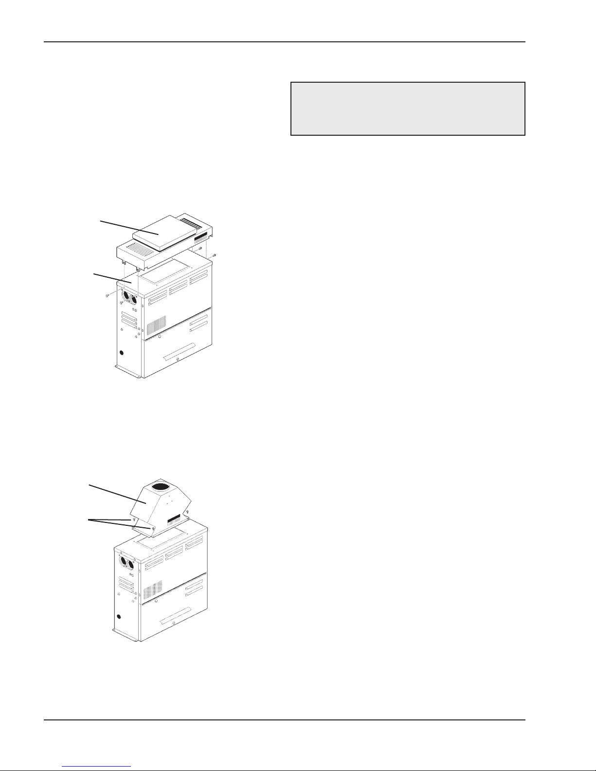
Outdoor
1. Remove the (4) screws which fasten jacket top to
heater.
2. Lower outdoor top onto unit lining up slots in outdoor top with screw holes in jacket top.
3. Reinstall (4) screws to secure jacket top and outdoor top to unit.
Outdoor Top
Jacket Top
Fig. 7: Heater with Outdoor Top
WARNING: Indoor boilers require a drafthood that
must be connected to a vent pipe and properly
vented to the outside. Failure to follow this procedure
can cause fire or fatal carbon monoxide poisoning.
Vent piping the same size or larger than the drafthood
outlet is recommended, however, when the total vent
height is at least ten (10) feet (drafthood relief opening
to vent terminal), the vent pipe size may be reduced as
specified in Chapter 10 of the latest edition of the
National Fuel Gas Code, ANSI Z223.1 (CanadaCAN/CGA B-149).
As much as possible, avoid long horizontal runs of
vent pipe a
horizontal or or non-vertical runs, the vent pipe must
have a minimum of 1/4 inch per foot rise and should be
supported at not more than five foot intervals.
Plumbers' tape, criss-crossed, will serve to space both
horizontal and vertical piping.
Gas vents supported only by the flashing and extending above the roof more than five feet should be
securely guyed o
loads. We recommend use of insulated vent pipe
spacer through the roofs and walls.
nd too many elbows. If installation requires
r braced to withstand snow and wind
Indoor
Locate and assemble as shown. Secure with screws
supplied in envelope inside carton.
Drafthood
Mounting
Screws
Fig. 8: Heater with Indoor Top
For protection against rain or blockage by snow, the
vent pipe must terminate with a vent cap which complies with the local codes or, in the absence of such
codes, to the latest edition of the National Fuel Gas
Code, ANSI Z223.1 (Canada-CAN/CGA B-149).
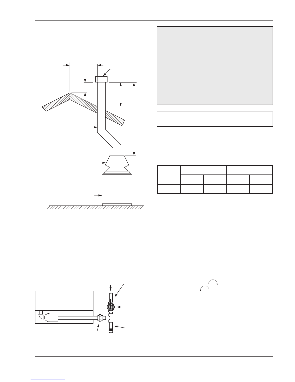
The discharge opening must be a m
tically from the roof surface and at least 2 ft. higher
than any part of the building within ten feet. Vent stack
shall be at least five feet in vertical height above the
drafthood outlet. The vent cap location shall have a
minimum clearance of 4 ft. horizontally from, and in no
case above or below, unless a 4-foot horizontal distance is maintained from electric meters, gas meters
egulators and relief equipment.
r
The weight of the vent stack or chimney must not rest
on heater drafthood. Support must be provided in
compliance with applicable codes. The heater top and
drafthood must be readily removable for maintenance
and inspection. Vent pipe should be adequately supported to maintain proper clearances from supported
to maintain proper clearances from combustible construction.
inimum of 2 ft. ver-
14
Page 15
Type "B" double wall or equivalent vent pipe is recom-
10' OR LESS
mended. However single-wall metal vent pipe may be
used as specified in the latest edition of the National
Flue Gas Code ANSI Z223.1 (Canada-CAN/CGA B-
149).
VENT CAP
2' MIN
2' MIN
CAUTION: The heater and its manual shut-off
valve must be disconnected from the gas supply
during any pressure testing of that system at test
pressures in excess of 1/2 psig (3.45 kPa). Dissipate
test pressure in the gas supply line before
reconnecting the heater and its manual shut-off
valve to gas supply line. FAILURE TO FOLLOW
THIS PROCEDURE MAY DAMAGE THE GAS
VALVE. OVER PRESSURED GAS VALVES ARE
NOT COVERED B
Y WARRANTY. The heater and its
gas connections shall be leak tested before placing
the appliance in operation. Use soapy water for leak
test. Do NOT use open flame.
5' MIN
VENT PIPE
DRAFT HOOD
HEATER
Fig. 9: Venting Clearances
Gas Supply Connections
Gas piping must have a sediment trap ahead of the
heater gas controls, and a manual shut-off valve located outside the heater jacket. All gas piping should be
tested after installation in accordance with local codes.
GAS
FLOW
SUPPLIED
BY OTHERS
NOTE: Do not use teflon tape on gas line pipe
thread. A flexible sealant is recommended.
A minimum of 7" WC and a maximum of 10.5" WC
upstream pressure under load, and no load conditions
must be provided for natural gas, or a minimum of 12"
WC and a maximum of 13" WC for propane.
1/2” 3/4”
Model
N P N P
055B 90 200 200 250
Natural Gas, 1000 BTU/FT3 .60 specific gravity @ 0.5” WC pressure
drop
Propane Gas, 2500 BTU/FT
sure drop
Table D: Maximum Equivalent Pipe Length
3
1.53 specific gravity @ 0.5” WC pres-
Gas Pressure Regulator
The gas pressure regulator is preset and sealed at 4"
WC for natural gas, and 11" WC for propane. Between
the gas valve and the burners is a 1/8" pipe plug. The
pressure at this point, taken with a manometer, should be
about 3.7" WC natural gas and 10.5" WC propane. If
an adjustment is needed, remove seal and turn adjustment screw clockwise to increase pressure or
counter-clockwise to decrease pressure.
UNION
Fig. 10: Sediment Trap
MANUAL
SHUT-OFF
VALVE
SEDIMENT
TRAP
15
Page 16
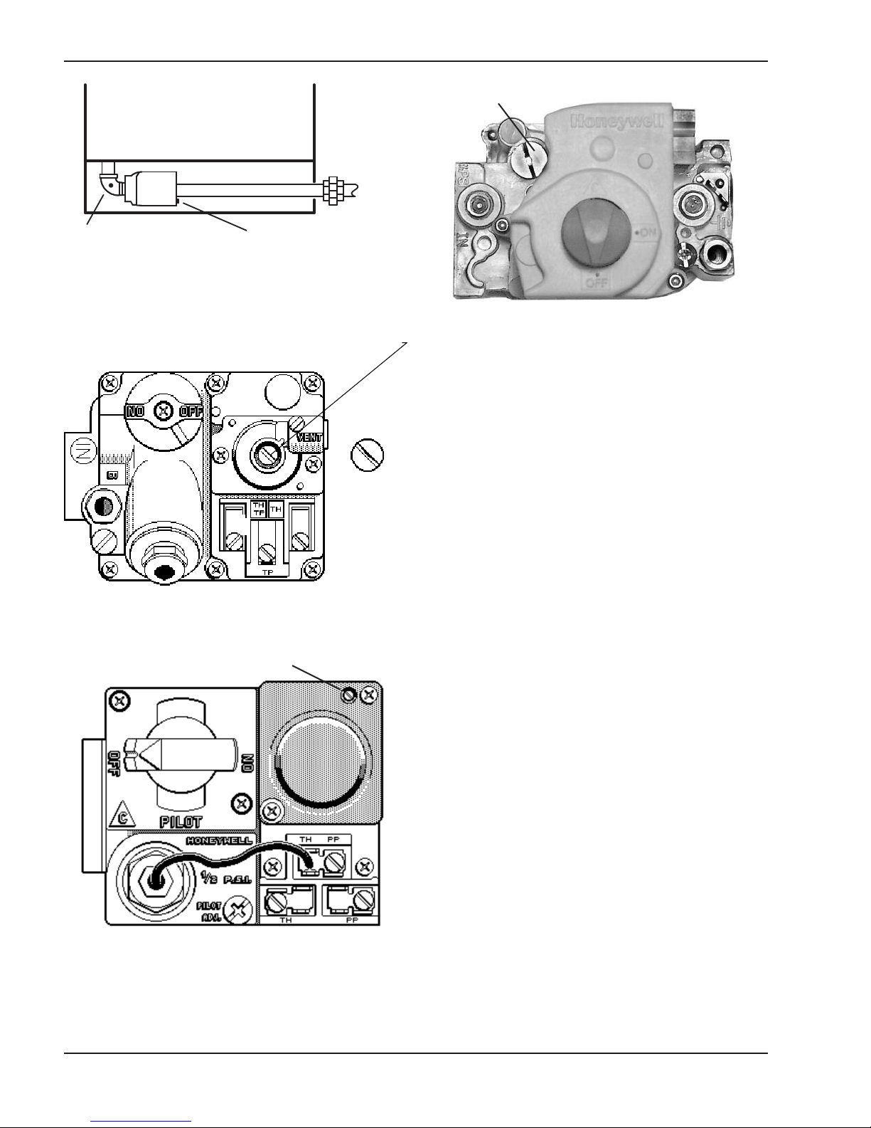
Valve
Gas Pressure Adjustment
Gas Pressure
Adjustment
Gas Pressure
Test at Heater
Fig. 11: Gas Pressure Testing Locations
Fig. 12: Robertshaw Millivolt Valve
Gas Pressure
Test at Gas
Fig. 14: Honeywell IID Valve
Plumbing for Water
Connections
Location
The VERSA heater requires water flow and positive
pressure to fire and operate properly. It must therefore
be installed downstream of the discharge side of the
filter pump. A typical installation is plumbed as follows:
1. The inlet side of the filter is plumbed directly to the
discharge side of the filter pump:
2. The outlet side of the filter is then plumbed to the
f the heater; and
inlet o
Gas Pressure Adjustment
Fig. 13: Honeywell Millivolt Valve
3. The outlet of the heater is plumbed to the return
line to the spa. The pump, filter and heater are
thus plumbed in series.
Plumbing from the heater back to the spa must not
have any valves or restriction that could prevent flow
when the pump is operating. To do so will void the warranty.
Heater must be located so that any water leaks will not
damage the structure of adjacent area. H
ture plastic pipe (CPVC) may be connected directly
into the heater if local codes permit.
16
igh tempera-
Page 17
Flow Rates
Inlet/Outlet Header
Pipe Size Min. gpm Max. gpm
Automatic Chlorinators and
Chemical Feeders
1-1/4” 20 60*
1-1/2” 20 60*
*When flow rates exceed 60 gpm, an external auxiliary bypass valve
is required. See External auxiliary bypass valve section for details.
Table E: Flow Rates
Companion Flange Connections
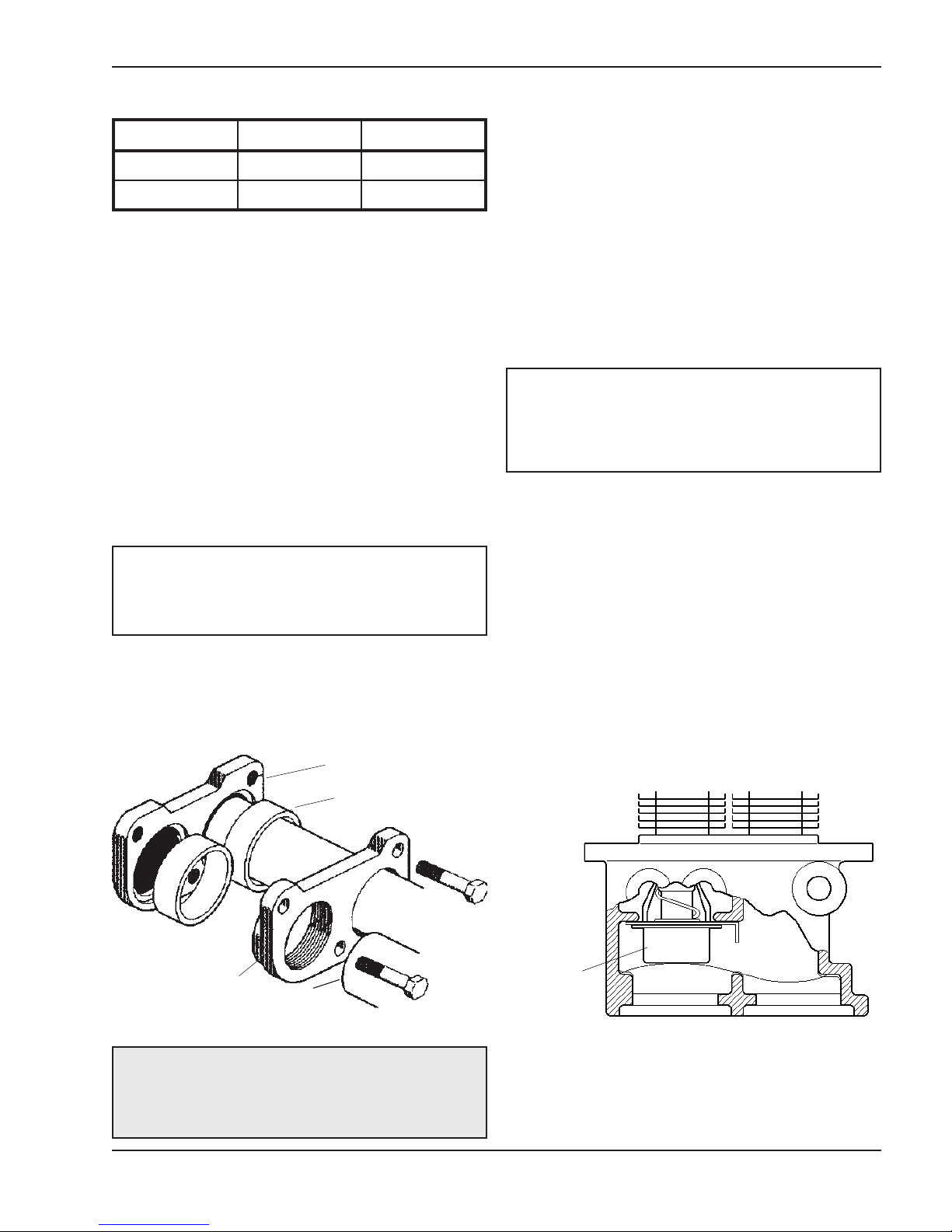
The inlet/outlet header flange accepts a 1-1/2" copper
tube or 1-1/4" galvanized pipe as a slip connection
directly into the manifold. The flange is also threaded
for 1-1/2" pipe thread. 1-1/2" CPVC adapters (when
available) can also be used.
PVC adapters should not be connected directly to the
header. The first 4 feet or 2 elbows of plumbing must
be of a high temperature m
copper before transitioning to PVC. This heater is a
low mass and low volume design.
NOTE: It is recommended that the heater be shut
down using its fireman switch 15 minutes prior to
pump shutdown, to remove residual heat from the
system.
aterial such as CPVC or
All chemicals must be introduced and completely diluted into the pool or spa water before being circulated
through the heater. Do not place chlorine tablets or
bromine sticks in the skimmer. High chemical concentrations will result when the pump is not running (e.g.
overnight).
Chlorinators must feed downstream of the heater and
have an anti-siphoning device to p
backup into the heater when the pump is shut-off.
NOTE: High chemical concentration from feeders
and chlorinators that are out of adjustment will cause
very rapid corrosion to the heat exchanger in the
heaters. Such damage is not covered under the
warranty.
revent chemical
Unitherm Governor Operation
The patented Unitherm Governor is a thermostatic
mixing valve specifically designed to maintain constant
heater internal temperature between 105 - 115°F
despite continually changing flow rates from the filter
and changing pool temperatures.
DO NOT use petroleum base assembly fluids (such as
petroleum jelly or lubricating oil). If assembly lube is
required, use a silicone-based compound, such as
Amoral, etc.
Flange Gasket
Header Flange
Pipe
Fig. 15: Header Connections
CAUTION: Do not install PVC directly into the
header flanges. The initial connection and the first 4
feet of plumbing or 2 elbows must be of high
temperature material such as CPVC or copper.
This narrow range is needed to prevent damaging
condensation on the burners w
heater runs for any length of time below 100°F. It is
also needed to inhibit scale formation in the tubes by
maintaining temperatures well below accelerated scaling temperatures.
hich will occur if the
Unitherm
Governor
Outlet Inlet
Fig. 16: Unitherm Governor Location
17
Page 18
External Auxiliary Bypass Valve
From Heater To Heater
T
Drain Pipe Drain Pipe
(Where Required)
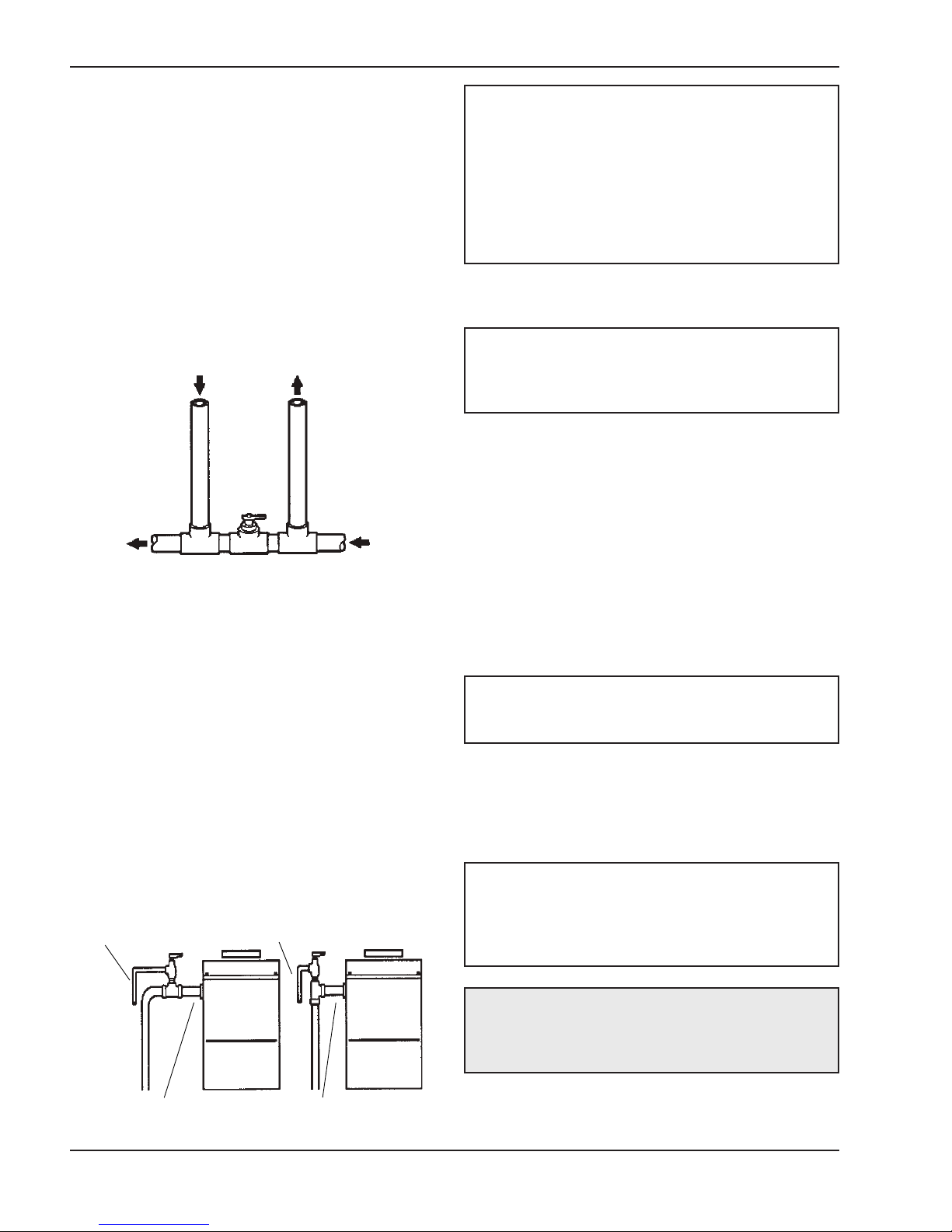
An auxiliary bypass valve should be used when flow
rates exceed 60 gpm (usually a high performance
pump size larger than 1-1/2 HP will exceed this flow
rate). This valve is required to complement the function of the automatic bypass valve, particularly when
starting the heater in winter or early spring when the
spa or pool temperature is down below 55°F. It a
serves to eliminate needless pressure drop through
the heater and accompanying reduction in the flow
rate to the spa jets, etc.
Auxiliary Bypass Valve (do not use gate valve)
Fig. 17: Auxiliary Bypass Valve
Auxiliary Bypass Valve Adjustment
lso
NOTE: To avoid water damage or scalding due to
valve operation, drain pipe must be connected to
valve outlet and run to a safe place of discharge.
Drain pipe must be the same size as the valve
discharge connection throughout its entire length
and must pitch downward from the valve. No shut-off
valve shall be installed between the relief valve and
the drain line. Valve lever should be tripped at least
once a y
ear to ensure that waterways are clear.
Electrical Wiring
NOTE: If it is necessary to replace any of the
original wiring, it must be replaced with 105°C wire or
its equivalent, except all black wire must be replaced
with 150°C wire or its equivalent.
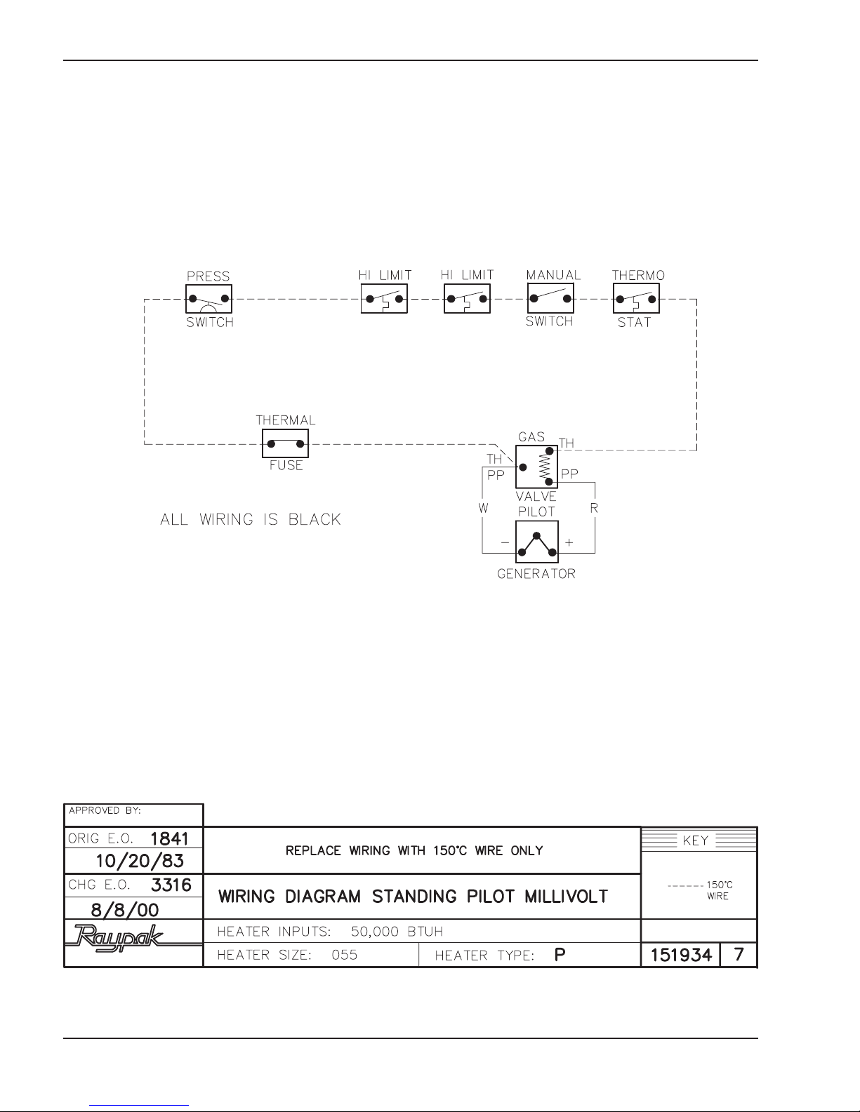
Millivolt System
The Millivolt System Residential Heater is equipped
with a self-generating electrical system in which the
electric current is provided by means of a pilot generator. No external electrical connections are required.
looP morF looP o
When installing a remote switch, do not exceed 10 ft.
of wiring from the heater. Use 18-gauge stranded wire.
Electronic Intermittent Ignition
Device (IID) System
To set bypass: With clean filter, adjustment is made by
feeling the inlet and outlet pipes at the heater. Outlet
pipes should be slightly warmer than inlet and comfortable to the touch. If pipe is hot, close bypass; if cold,
open bypass
Pressure Relief Valve Installation
To conform to local building codes, it may be necessary to install a pressure relief valve. A 3/4" pressure
relief valve having a capacity equal to BTUH/HR output of the model to be installed is recommended for
this appliance.
Heater Outlet Heater Outlet
Fig. 18: Pressure Relief Valve Installation
NOTE: When the electrical hookup to the heater
requires both 24V and 120V or 240V, each input
voltage must be isolated in a separate conduit.
The Electronic Intermittent Ignition Device automatically lights the pilot and main burners upon a call for
the heat. The heater is supplied with a dual-voltage
transformer for 120V or 240V input power hookup.
NOTE: IID Propane Units Only Heater is equipped
with an electronic ignition device with a 100% safety
lockout feature. If the heater fails to start or lockout,
reset the ignition device by interrupting the power to
the heater for 60 seconds.
CAUTION: If service replacement of the electronic
ignition device is required, replace only with a 100%
safety lockout device with 90-second trial for pilot
ignition.
18
Page 19
120V ATMOSPHERIC HEATER 120V LOW NOx HEATER
H
L
B
240V ATMOSPHERIC HEATER
H
B
R
H
G
S
HOT
L1
BLACK
BLACK
Robertshaw Intermittent
Ignition Device
Honeywell Intermittent
Ignition Device
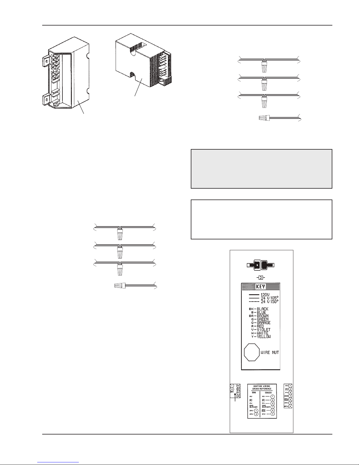
Fig. 19: Intermittent Ignition Devices
For 120 V input power to the unit, connect the black
wire to the “L1”, or hot leg, of the power supply.
Connect the white wire to the “L2”, or neutral leg, of the
power supply. Attach the wire nut to the red wire. There
should be no connection to the red wire for 120V operation.
HOT
SUPPLY
SIDE
RETURN
or
NEUTRAL
GROUND
L1
BLACK
BLACK
WHITEWHITE
GREENGREEN
HEATER
4 WIRES
SUPPLY
SIDE
HOT
L2
RED RED
GREENGREEN
WHITE
HE ATER
4 WIRES
Fig. 21: 240V Wiring
CAUTION: Heater must be electrically grounded
and bonded in accordance with local codes, or, in the
absence of local codes, with the latest edition of the
National Electrical code, ANSI/NFPA 70 (CanadaCanadian Electrical Code, CSA C22.1, Part 1).
NOTE: Input power to the heater (120/240V) should
be supplied from the load (pump) side of time clock
or switch. Connecting heater to continuous power
source will allow "Fail" indications (service and
pressure switch) when pump is not operating.
WIRING DIAGRAM KEY
PINK CONNECTOR BLUE CONNECTOR
RED
Fig. 20: 120V Wiring
For 240 V input power to the unit, connect the black
wire to the “L1”, or hot leg, of the power supply.
Connect the red wire to t
he “L2”, or second hot leg, of
the power supply. Attach the wire nut to the white wire.
There should be no connection to the white wire for
240V operation.
19
SPK
0068S 68S
Page 20
Wiring Diagram—Millivolt Units with Mechanical Thermostat
20
Page 21
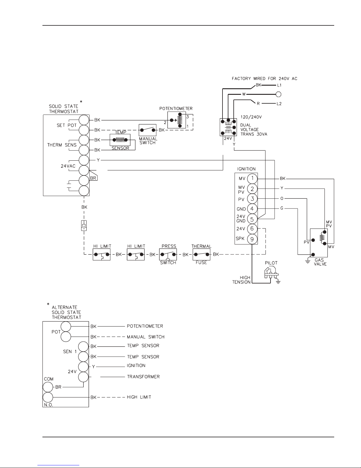
Wiring Diagram—IID Units
BL
BL
BL
21
Page 22
SERVICE
Drain Valve
Solid State Thermostat &
Controls/Adjustments/
Replacements
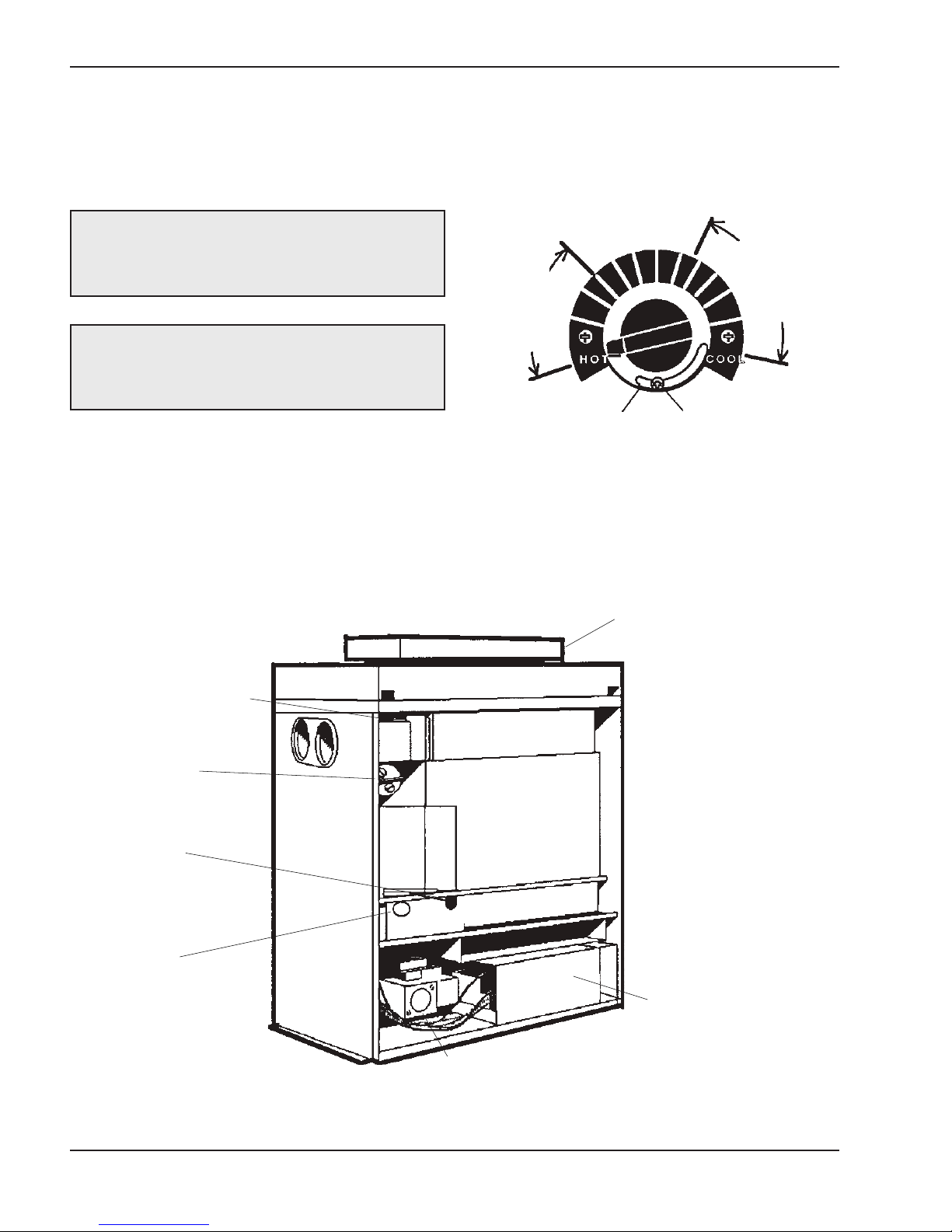
The thermostat is fitted with a means of limiting the
upper temperature limit below the maximum level. The
knob stop adjustment ring illustrated above is
adjustable by loosening the set screw, rotating the
knobstop ring to the desired location and retightening
the set screw.
DANGER - SHOCK HAZARD - Make sure
electrical power to the heater is disconnected to
avoid potential serious injury or damage to
components.
CAUTION: Label all wires prior to disconnection
when servicing controls. Wiring errors can cause
improper and dangerous operation. Verify proper
operation after servicing.
Temperature Controls
The water temperature is controlled by the heater thermostat on the upper front panel of the heater. The
control center contains an On-Off toggle switch and a
thermostat. The switch functions as a means for turning the heater on or off.
HIGH LIMITS
(Located in the
Inlet/Outlet
header)
Typical
Comfortable
Spa
Temperature
Range
Knobstop Ring Set Screw
Typical
Comfortable
Pool
Temperature
Range
Fig. 22: Knobstop Setting
Pressure Switch
Burner & Pilot
Thermal Fuse
Valve
Gas
Fig. 23: General Location of Controls
22
Ignition Control
Page 23
Pressure Switch
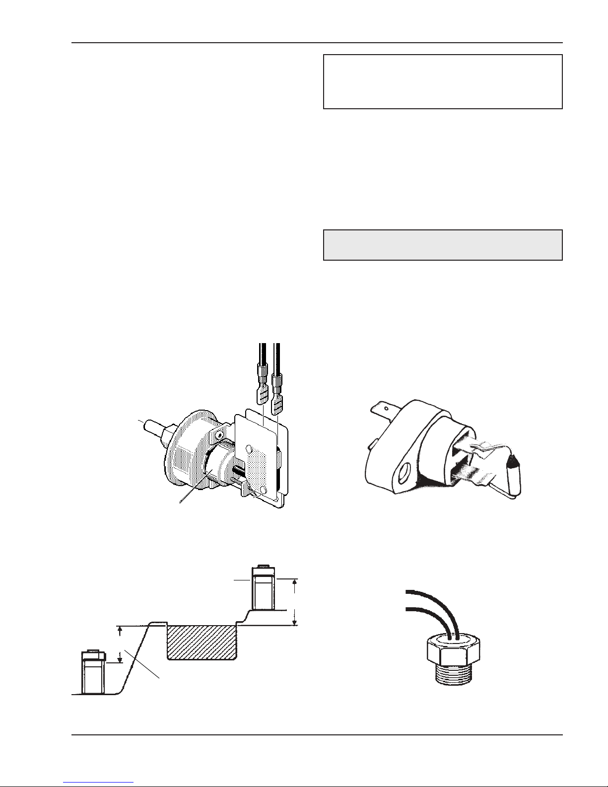
The pressure switch, or heater actuator, ensures that
the heater operates only when the filter pump is in
operation. It is factory set at 1.75 PSI for deck level
installations. When the heater is located below the
level of the spa or pool, it may be necessary to reset
the pressure switch to compensate for the no-flow
static head. If it is necessary to reset the pressure
switch, we recommend t
Pressure Switch Adjustment
1. With pump and heater on, turn adjustment knob
(clockwise) until a click is heard from the gas
valve.
2. Turn adjustment knob (counter-clockwise) 1/4
turn.
3. Turn pump off and on several times. Heater should
shut-off immediately. If it does not, repeat steps
above until proper adjustment is made.
he following procedure.
NOTE: If heater is installed outside of the limits
shown, a flow switch must be used in place of the
pressure switch when mounted and wired adjacent
to the heater.
Two-Speed Pumps
In some cases, the flow on the low-speed is insufficient to operate the heater. This is apparent when the
pressure switch cannot be further adjusted or if the
heater makes banging noises. In these cases, the
pump must be run at high speed when heating the
water.
CAUTION: Do not operate the heater without the
function of a properly adjusted pressure switch.
Flame Roll-Out Safety Switch
The heater is equipped with a thermal cut-off device to
prevent flame roll-out in the event the heat e
becomes blocked. This is a "single-use" type fusible
link or thermal fuse, that must be replaced when disabled by an over temperature condition, caused by
excessive restriction in the heat exchanger flue passage.
xchanger
Adjustment Knob
Fig. 24: Pressure Switch Adjustment
Heat Exchanger Height
5' Max.
Heat Exchanger Height
Fig. 25: Above/Below Installation Limits
Fig. 26: Flame Roll-Out Safety Switch
High Limits
The heater is equipped with two automatic high limits,
set to operate at 135°F and 140°F.
5' Max.
Pool or Spa
Fig. # 8152.0s
Fig. 27: High Limit
23
Page 24
NOTE: An erratic high limit is often characteristic of
internal heat exchanger problem, e.g. scale build-up,
U.G. operation. Refer to Troubleshooting section.
High Limit Removal
Main Burner and Orifice Removal
1. Remove burner tray. (See Burner Tray Removal
procedure).
2. Remove screws and burner hold-down bracket.
1. Disconnect top portion of unit. (See Heat
Exchanger Removal procedure, steps 1 thru 7 and
step 10.)
2. Remove defective high limit and replace with new
high limit.
3. Reverse above procedure to reinstall.
Pilot Safety
Millivolt Units
The heaters equipped with the standing pilot (millivolt
system) have pilot generators which act as a safety
device to shut-off the flow of gas to the main burners
a
nd the pilot burner in case the pilot flame is extinguished. The pilot burner must be manually relighted
to place the heater in operation again. Refer to the
lighting instructions provided on the heater label.
IID Units
The heater employs a pilot safety which closes the
main gas valve within 8/10ths of a second whenever
the pilot flame is interrupted. Pilot flame is automatically lit when the device i
safety check and opens the main valve only after the
pilot is proven to be lit.
s powered. Unit performs its own
NOTE: If the heat exchanger is sooted badly, the
burner hold-down bracket and spacer can become
distorted from direct flame impingement and this
usually necessitates replacement of these parts.
3. Lift burners from slotted spacers and slide from
orifices. Clean with a wire brush.
4. Orifices usually do not need to be replaced. To
clean, run either copper wire or wood toothpick
through orifice. Do not enlarge hole. To remove
orifice, use a socket wrench and remove f
manifold. DO NOT over-tighten when reinstalling.
rom
Pilot Removal and Cleaning
1. Remove burner tray. (See Burner Tray Removal
procedure).
2. Disconnect pilot tubing, disconnect wires from gas
valve (millivolt unit only).
3. Disconnect pilot bracket from burner shield.
4. Remove pilot from bracket.
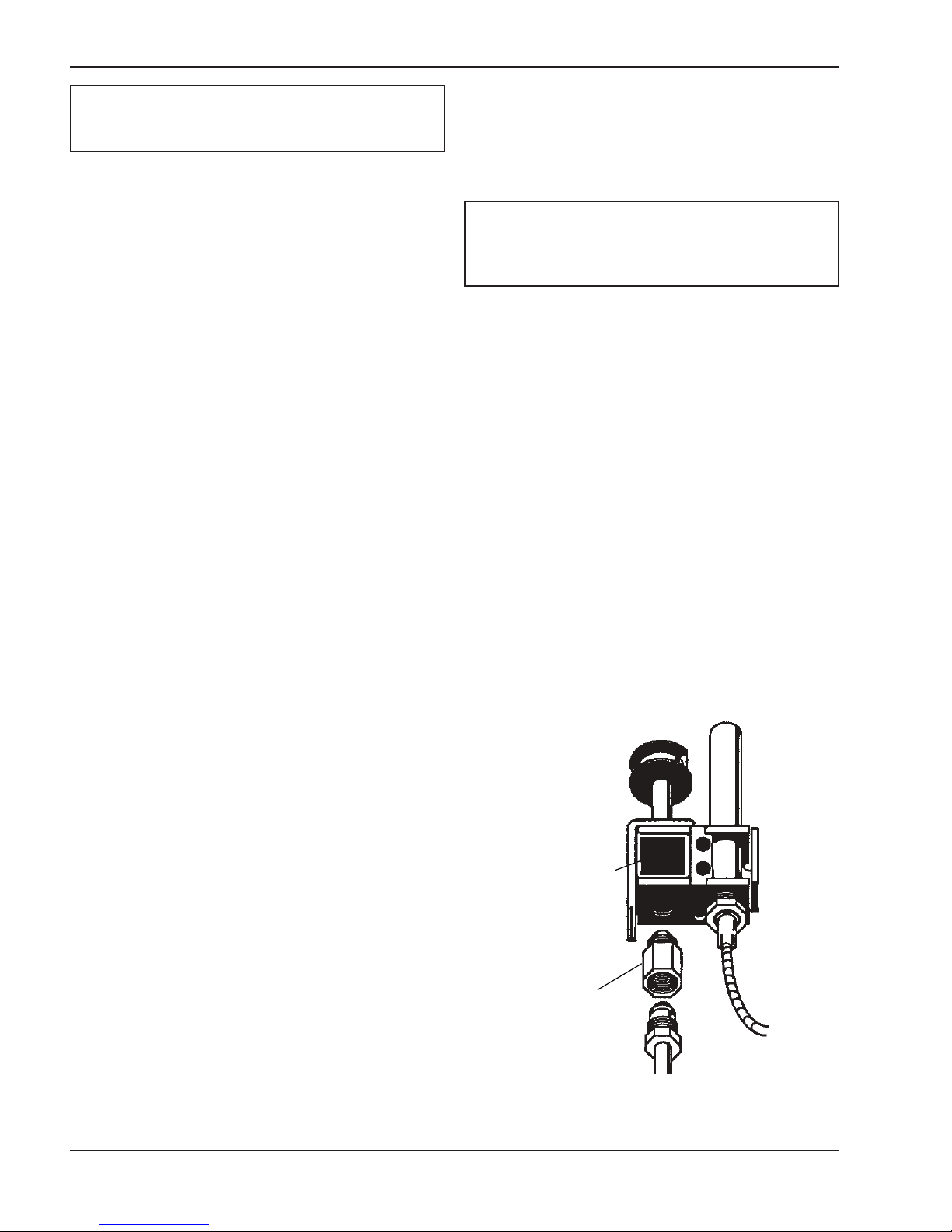
5. Remove pilot orifice and air opening (Honeywell
MILLIVOLT unit only), and clean with wire or small
brush. C
orifice.
6. Reverse above procedure to reinstall.
AUTION! DO NOT enlarge hole in pilot
Burner Tray Removal
1. Shut-off main electrical power switch to heater.
2. Shut-off gas upstream of heater.
3. Remove front door.
4. Disconnect gas line from gas valve.
5. Remove (2) screws that mount burner tray to unit.
6. Disconnect wires that terminate at gas valve, and
thermal fuse.
lide out burner tray.
7. S
8. Reverse above procedure to reinstall.
Gas Valve Removal
1. Remove burner tray. (See Burner Tray Removal
procedure).
2. Disconnect pilot tubing from gas valve.
3. Remove gas valve with manifold from burner tray.
4. Remove manifold from gas valve.
5. Reverse above procedure to reinstall.
toliP
Air
Opening
Orifice
Fig. 28: Honeywell Pilot
24
Page 25
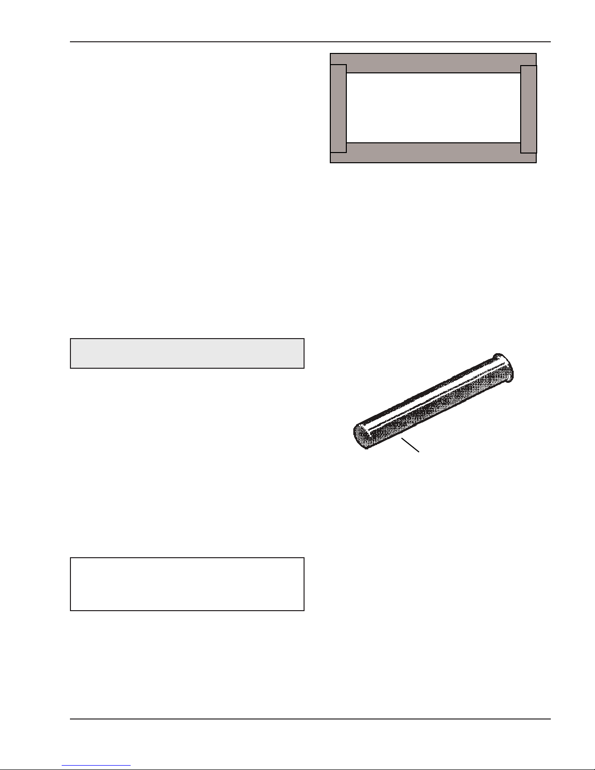
Heat Exchanger Removal
Immersion Well
1. Shut water, gas, and electricity off, close valves
and relieve pressure.
2. Drain heat exchanger.
3. Loosen and remove flange bolts.
4. Remove flange and inlet/outlet pipes from the
header. Remove drain valve from rear header.
5. Remove outdoor stackless top or indoor stack top
from unit.
6. Remove jacket top, flue collector, and baffle.
7. Remove upper front jacket panel, and disconnect
ires at toggle switch.
w
8. Remove capillary bulb from inlet/outlet header.
9. Disconnect press switch tube from inlet/outlet
header.
10. Disconnect high limit wire from thermostat, and
pressure switch.
11. Lift heat exchanger straight up from combustion
chamber, using caution not to damage refractory.
12. Reverse above procedure to reinstall.
De-sooting Procedure
CAUTION: Soot is combustible. Exercise extreme
care. Never use a wire brush.
Fig. 29: Refractory Panel—Top View
Control Immersion Well
Replacement
1. Remove plumbing and top portion of unit (See
Heat Exchanger Removal procedure, steps 1
through 6).
2. Remove U.G. spring, U.G. and copper shield.
3. Collapse well tube at open end with chisel.
4. Push well up through header.
5. Insert new well and roll in place. If a roller is not
available, solder the well in place with silver solder.
Soot can clog areas between fins and cause eventual
tube failure. Any sign of soot at the base of the burners or around the outer jacket indicates a need for
cleaning.
1. Disconnect top portion of unit. (See Heat
Exchanger Removal procedure steps 1 through
6).
2. Remove burner tray (See Burner tray Removal
procedure.)
3. Take a garden hose and wash heat exchanger,
making sure soot is removed completely from
between fins. Avoid excessive water against
efractory.
r
NOTE: In extreme cases it may be necessary to
remove the heat exchanger completely for cleaning.
The simplest method is steam cleaning at the local
car wash. DO NOT WIRE BRUSH.
Combustion Chamber Removal
1. Remove heat exchanger (See Heat Exchanger
Removal procedure).
2. Lift up and remove front and rear refractory shield.
3. Remove refractory panels.
4. Reverse above procedure to reinstall.
Fig. 30: Immersion Well
Unitherm Governor (U.G.)
Replacement
1. Shut water, gas and electricity off, close valves
and relieve pressure.
2. Drain heat exchanger.
3. Disconnect inlet and outlet pipes with flange from
in/ out header.
4. Grasp retainer spring from inlet side of header,
and slide thru inlet hole.
5. Remove shield.
6. Remove U.G. with seating gasket, and stainless
steel baffle (not shown).
7. Reverse above procedure to re-install.
25
Page 26
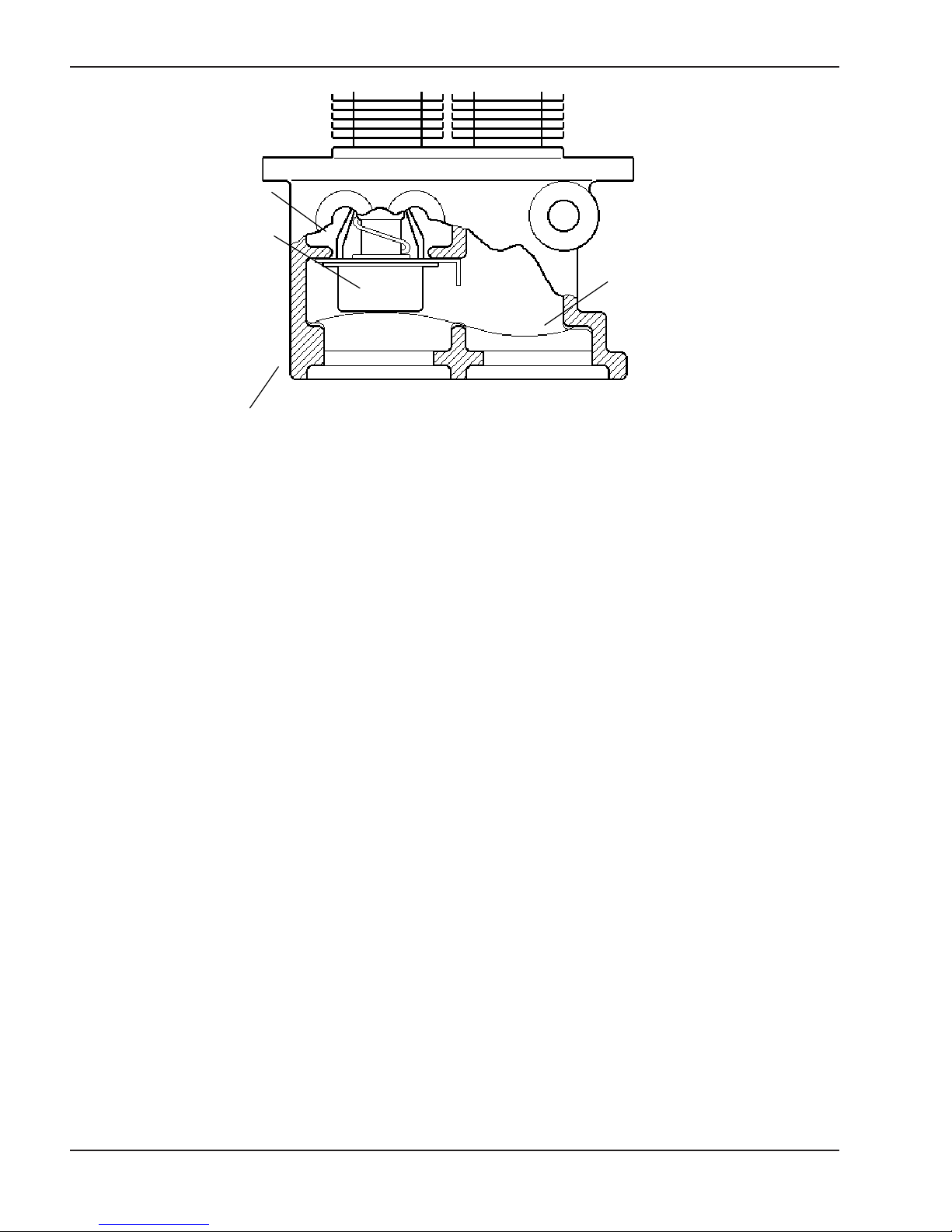
U.G.
U.G.
Shield
Retainer
Spring
Outlet Inlet
Inlet/Outlet
Header
Fig. 31: Unitherm Governor Location
To test the operation of the Unitherm Governor, place in hot water (over 110°F) and watch for movement against
spring. If there is no movement, replace unit.
26
Page 27

These instructions are primarily intended for use by qualified personnel specifically trained and experienced in the
i
be required by some states to be licensed. Persons not q
repairs according to these instructions.
Heater going on and off Dirty filter............................................. B
conti
SH
P
Ye
Takes long time to heat Unde
p
TROUBLESHOOTING
nstallation of this type of heating equipment and related system components. Installation and service personnel may
ualified shall not attempt to install this equipment nor attempt
MECHANICAL
PROBLEM CAUSE SOLUTION
Harmonics, or whining noise U.G. inoperative................................. Check movement by putting in hot water (110°F
or higher). If no movement, replace.
*Debris or restriction in system....... Locate the restriction and remove. Flush system
and clean.
*Debris in gas line.............................. Remove debris or blow out gas line.
Low flow.............................................. Scale forming in heat exchanger - clean heat
exchanger and check pool pH and total alkalinity.
ackwash filter.
nuously Low water level in pool.................... Raise water level.
External bypass setting out of
adjustment......................................... Adjust bypass.
*Pressure switch out of
adjustment......................................... Adjust pressure switch.
Liming or scale forming on Pool water chemical imbalance.... See Water Chemistry on page 2.
heat exchanger
gnitoo
igh flow rates.................................. Reduce by adding manual bypass valve and
U.G. inoperative................................. C heck movement by putting in hot water (110°F
llow lazy flame Low gas pressure............................ Adjust gas pressure.
Outer jacket very hot *Broken refractory caused by
(paint blistered) shipping damage or improper
ool or spa formula:
*Air starvation....................................... Refer to installation instructions.
*Improper venting............................... Follow recommended installation instructions.
*Insects or debris clogging
burner intake ports........................... Clean burners.
Restricted pilot.................................. Clean pilot.
Weak pilot generator........................ Replace pilot.
*Insects or debris clogging
burner intake ports........................... Clean burners.
combustion........................................ Replace refractory panels.
Excessive sooting of heat
exchanger........................................... Determine cause of sooting & correct.
rsized heater............................. Check heat rise per hour with the following
Filter not running long enough....... Reset time clock.
Dirty filter............................................. C lean filter.
Gas line or meter undersized......... Refer to installation instructions.
(* Usually occurs on initial start-up.)
adjust by putting thermometer in header (1/4"
NPT) drain opening. Set bypass so thermometer reads between 105° and 110°F.
or higher). If no movement, replace.
.erusserp sag tsujdA............................erusserp sag woLegatuo toli
Heat rise (°/hr.)= Heater Output
Pool gallonage x 8.33
27
Page 28
replace.
U.G. not functioning...................... Replace if no movement when heated.
Leaking at well Overacid.................................. Replace well and maintain water chemistry
properly.
Leaking at heat exchanger Overacid.................................. Replace heat exchanger and maintain
chemistry properly.
Gasket brittle and leaking - Heater running after pump
(overhea ted) shuts off................................... See pressure switch adjustment.
Refractory damage..................... Replace refractory.
Sooted heater............................ Determine cause of sooting and correct.
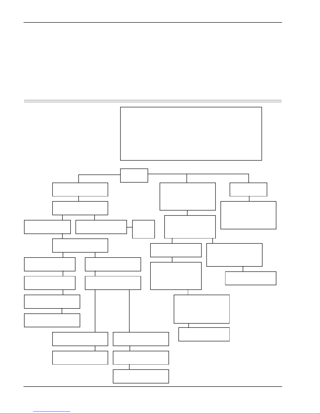
ELECTRICAL - MILLIVOLT
POOL OR SPA HEATER ELECTRICAL
CHECK WITH MILLIVOLT GAS VALVE
CAUTION: For qualified service personnel only.
1. Filter must be on with adequate water flow through heater.
2. Gas valve must be in "ON" position and the thermostat
set higher than the pool water temperature.
3. Jumpers are for temporary check only. If left in place,
they could cause the heater to burn up.
Light pilot
,tnemevom on fi ,tnemevom rof ssapyb tcepsnI............retaw hcum oot gnissapyBgnimiL
If pilot burner remains lit
Jump across both "TH"
wires on gas valves
If main burner fires,
remove jumper
Jump across pressure
switch terminals
If main burner fires,
remove jumper
Clean filter
Check for adequate water
flow from filter
Replace pressure switch
If main burner fires,
remove jumper
If main burner does not
fire, remove jumper
If main burner does not
fire, remove jumper
Jump across thermostat
If main burner does
Replace
gas
valve
NOT fire...
If pilot burner goes out
when main burner lights
or when gas valve knob
is released
Remove both "TH"
wires from gas valve.
Re-light pilot
If pilot burner stays on
Problem is a wire or
component short to
cabinet or low gas
pressure
If below 500millivolt,
check
gas pressure. Also check
for insects or debris in
the pilot burner
If output is still low,
replace pilot generator.
If pilot burner
does not light
Check gas supply, gas
line size, gas pressure.
Also check for insects
or debris in pilot output.
If burner does not remain
lit, attach millivolt meter
and read pilot output.
If above 500millivolt,
replace gas valve
Replace thermostat
Jump across each high
limit and remove jumper
Replace high limit that
caused heater to fire
28
Page 29
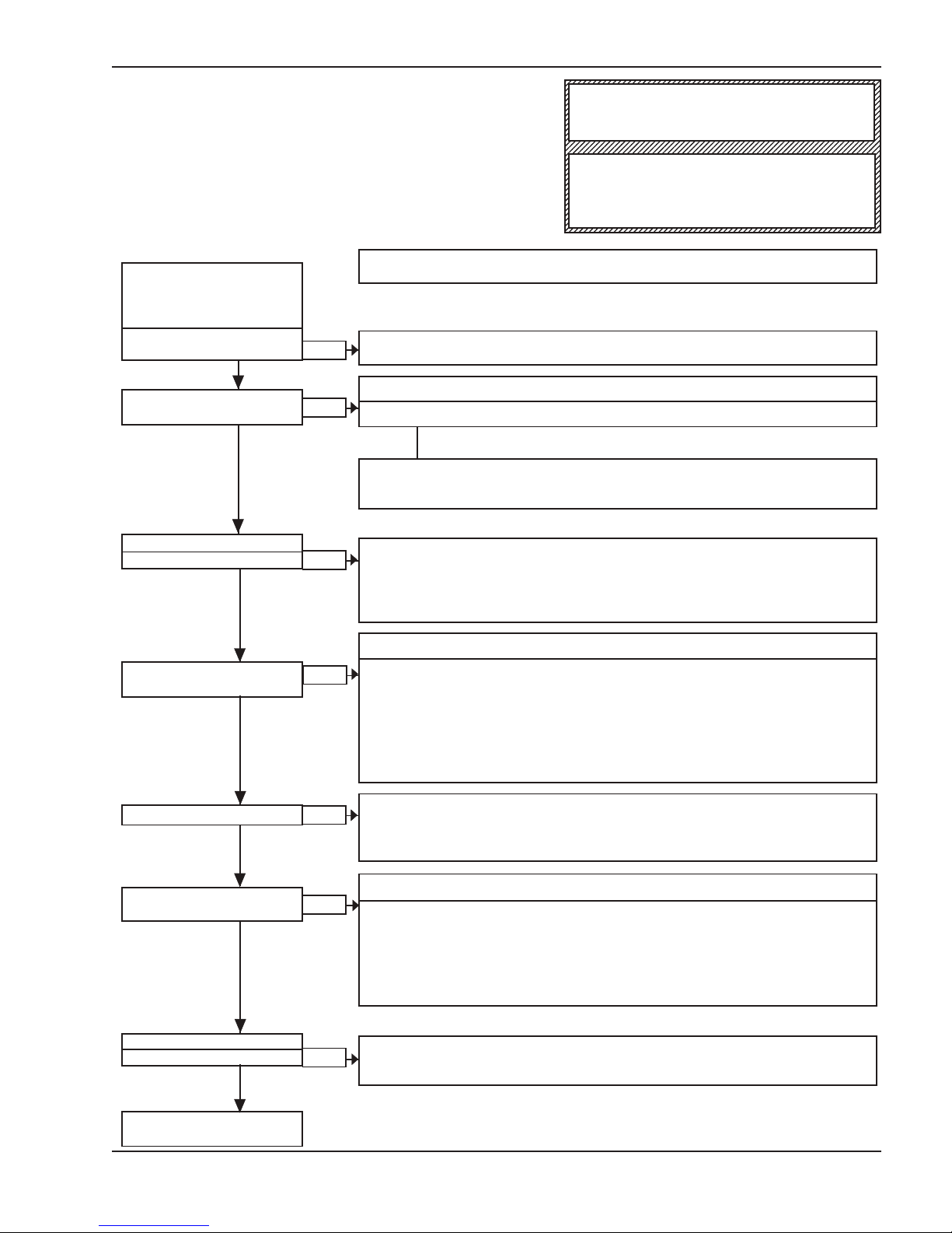
ELECTRICAL - IID
WARNING
HIGH VOLTAGE
For qualified Technicians ONLY
Intermittent Pilot System
TROUBLESHOOTING HONEYWELL S8600
START
TURN GAS SUPPLY OFF.
TURN THERMOSTAT
(CONTROLLER) TO CALL
FOR HEAT
POWER TO MODULE
(24 V NOMINAL)?
YES
SPARK ACROSS
IGNITER/SENSOR GAP?
YES
TURN GAS SUPPLY ON
PILOT BURNER LIGHTS?
YES
NO
NO
NO
NOTE: Before troubleshooting, familiarize yourself with the start-up and checkout
procedure.
Check line voltage power, low voltage transformer, limit controller, thermostat
(controller) and wiring.
Pull ignition lead and check spark at module.
Spark Okay?
YES
• Check ignition cable, ground wiring, ceramic insulator and gap, and correct.
• Check boot of the ignition cable for signs of melting or buckling. Take protective
action to shield cable and boot from excessive temperatures.
• Check that all manual gas valves are open, supply tubing and pressures are
good, and pilot burner orifice is not blocked.
• Check electrical connections between module and pilot operator on gas control.
• Check for 24 Vac across PV-MILLIVOLT/PV terminals on module. If voltage is
okay, replace gas control; if not, replace module.
NOTE: Some heaters may be equipped with
an ignition module that shuts off pilot gas if
pilot fails to light. To reset, interrupt power to
heater.
SPARK STOPS WHEN
PILOT IS LIT?
YES
MAIN BURNER LIGHTS?
YES
SYSTEM RUNS UNTIL
CALL FOR HEAT ENDS?
YES
CALL FOR HEAT ENDS
SYSTEM SHUTS OFF?
YES
NO
NO
NO
NO
NOTE: If S8600H goes into lockout, reset system.Lockout is used on L.P.G models.
• Check continuity of ignition cable and ground wire.
• Clean flame rod.
• Check electrical connections between flame rod and module.
• Check for cracked ceramic flame rod insulator.
• Check that pilot flame covers flame rod and is steady and blue.
• Adjust pilot flame.
• If problem persists, replace module.
• Check for 24 Vac across MILLIVOLT-MILLIVOLT/PV terminals. If no voltage,
replace module.
• Check electrical connections between module and gas control. If okay, replace
gas valve or gas control operator, i.e. pilot gas valve, flow switch etc.
NOTE: IF S8600H goes into lockout, reset system.
• Check continuity of ignition cable and ground wire.
NOTE: If ground is poor or erratic, shutdowns may occur occasionally even though
operation is normal at the time of checkout.
• Check that pilot flame covers flame rod and is steady and blue.
• If checks are okay, replace module.
• Check for proper thermostat (controller) operation.
• Remove MILLIVOLT lead at module; if valve closes, recheck temperature control ler and wiring; if not, replace gas valve.
TROUBLESHOOTING
ENDS
Repeat procedure until trouble-free operation is obtained.
29
Page 30
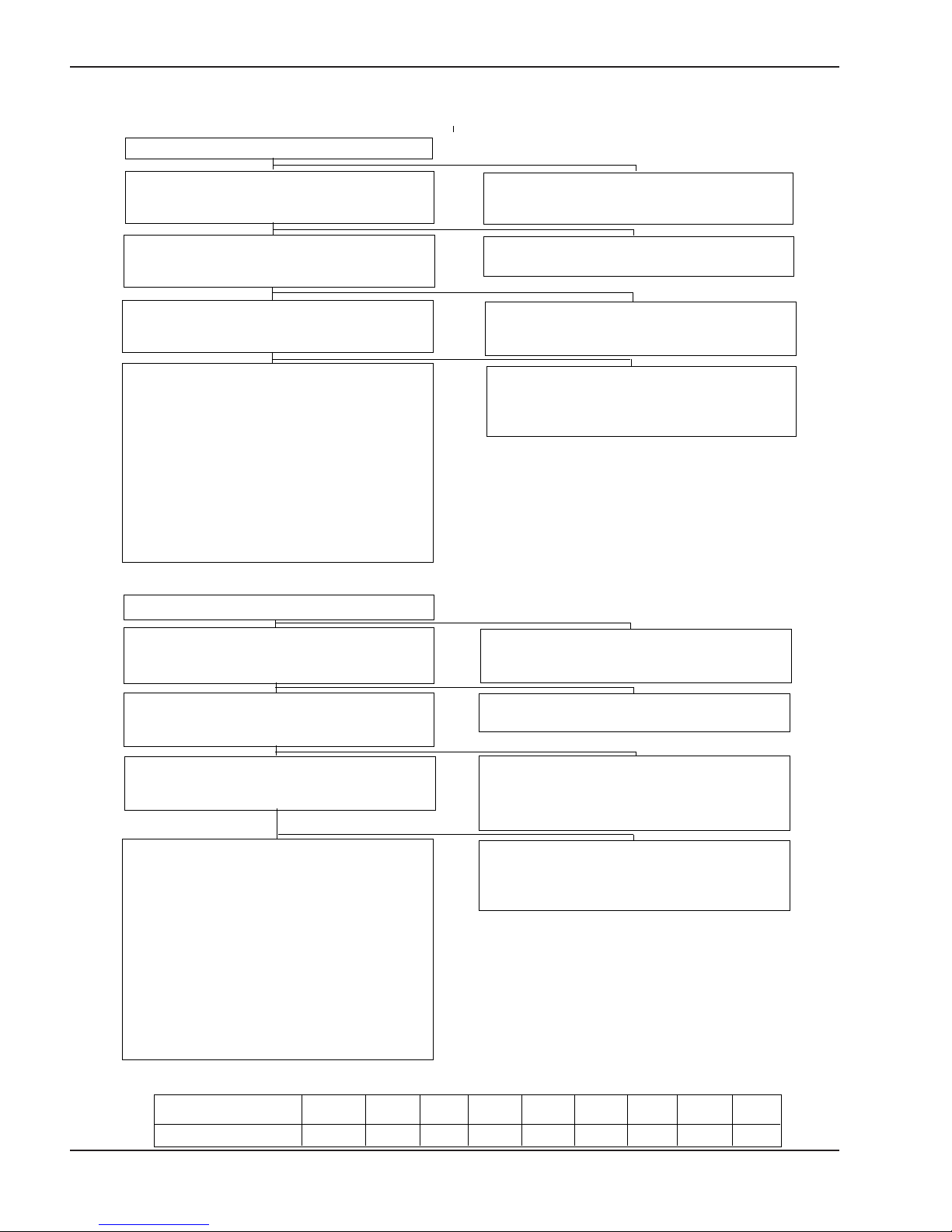
ELECTRICAL - IID, SOLID STATE THERMOSTAT
If the pool/spa/hot tub water is too cold, troubleshoot the system as follows:
Check voltage at 24 V terminals.
VOLTAGE BETWEEN 21.5-28.5 V.
Set control to max. temperature. After 2-3
cycles, check water temperature.
TEMPERATURE BELOW 105°F
Disconnect sensor leads from circuit board.
Measure sensor resistance with ohmmeter.
RESISTANCE 1-14k OHMS.
Check water temperature; estimate expected sensor resistance from chart below.
MEASURED AND ESTIMATED RESISTANCE
MATCH WITHIN 20 PERCENT.
Disconnect potentiometer leads from circuit board.
Measure resistance with ohmmeter. If resistance
is: 0-100 ohms at minimum setting and
9k to 11k at maximum setting,
replace circuit board.
Above 11k ohms but less than
15 k ohms, replace potentiometer.
Above 15k ohms, fix loose or broken wires;
replace potentiometer if necessary.
Reconnect all leads and check out system.
If the pool/spa/hot tub water is too hot, troubleshoot the system as follows:
Check voltage at 24 V terminals.
VOLTAGE OUTSIDE RANGE 21.5-28.5 V.
Check transformer, 120 V supply, correct as
necessary
TEMPERATURE 105-106° F.
Control ok.
RESISTANCE 0 OHMS (SHORT CIRCUIT)
Check system for shorted wires or open circuits.
Replace sensor if necessary.
MEASURED AND ESTIMATED RESISTANCE
DON'T MATCH.
Replace sensor. Reconnect all leads and check
out
system.
VOLTAGE BETWEEN 21.5-28.5 V.
Set control to max. temperature. After 2-3
cycles, check water temperature.
TEMPERATURE ABOVE 108°F
Disconnect sensor leads from circuit board.
Measure sensor resistance with ohmmeter.
RESISTANCE 1-14k OHMS.
Check water temperature; estimate expected
sensor resistance from chart below.
MEASURED AND ESTIMATED RESISTANCE
MATCH WITHIN 20 PERCENT.
Disconnect potentiometer leads from circuit board.
Measure resistance with ohmmeter. If resistance
is:
0-100 ohms at minimum setting:
9k to 11k at maximum setting,
replace circuit board.
Above 11k ohms, replace
potentiometer.
0 ohms (short circuit), replace
potentiometer.
Reconnect all leads and check out
Temperature
(deg. F) 61 68 70 77 86 88 95 104 106
Resistance (k ohms) 14.92 12.49 11.88 10.00 8.06 7.69 6.53 5.33 5.1
system.
SENSOR RESISTANCE AT VARIOUS TEMPERATURES
VOLTAGE OUTSIDE RANGE 21.5-28.5 V.
Check transformer, 120 V supply, correct as
necessary.
TEMPERATURE 105-106° F.
Control ok.
RESISTANCE ABOVE 15k OHMS (OPEN
CIRCUIT) OR SHORT CIRCUIT.
Fix loose or broken wires. Replace sensor if
necessary.
MEASURED AND ESTIMATED RESISTANCE
DON'T MATCH.
Replace sensor. Reconnect all leads and check
out system.
0
30
Page 31

REPLACEMENT PARTS
LIST
In order to receive the correct part it is important that
you state the model number, serial number and type of
gas when applicable.
Any part returned for replacement under standard
company warranties must be properly tagged with
return parts tag, completely filled in with the heater
serial number, model number, etc., and shipped to the
Company freight prepaid.
If determined defective by the Company and within
warranty, the part will be returned in kind or equal substitution, freight collect. Credit will not be issued.
Manufacturer:
2151 EASTMAN AVENUE
OXNARD, CA 93030
31
Page 32
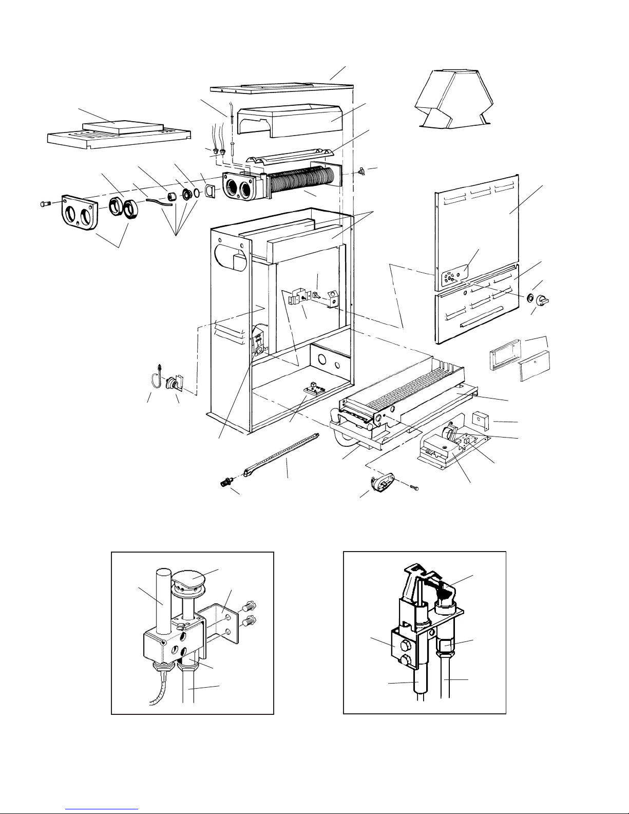
1-S
2-V
1-V
12-H
11-H
5-H
6-H
10-H
4-H
14-H
7-C
1-C
2-C
13-H
8-H
7-M
6-C
2-H
2-S
3-H
7-H
1-R
5-M
3-M
4-S
3-S
4-M
6-S
2-M
1-M
Fig # 240654
HONEYWELL MILLIVOLT PILOT
9-P
3-C
1-P
5-P
14-P
3-B
12-P
5-C
2-B
1-G
9-M
HONEYWELL IID PILOT
13-P
15-P
1-B
5-S
6-M
4-C
11-P
3-P
7-P
14-P
Fig # 8132
Fig # 8133
32
Page 33
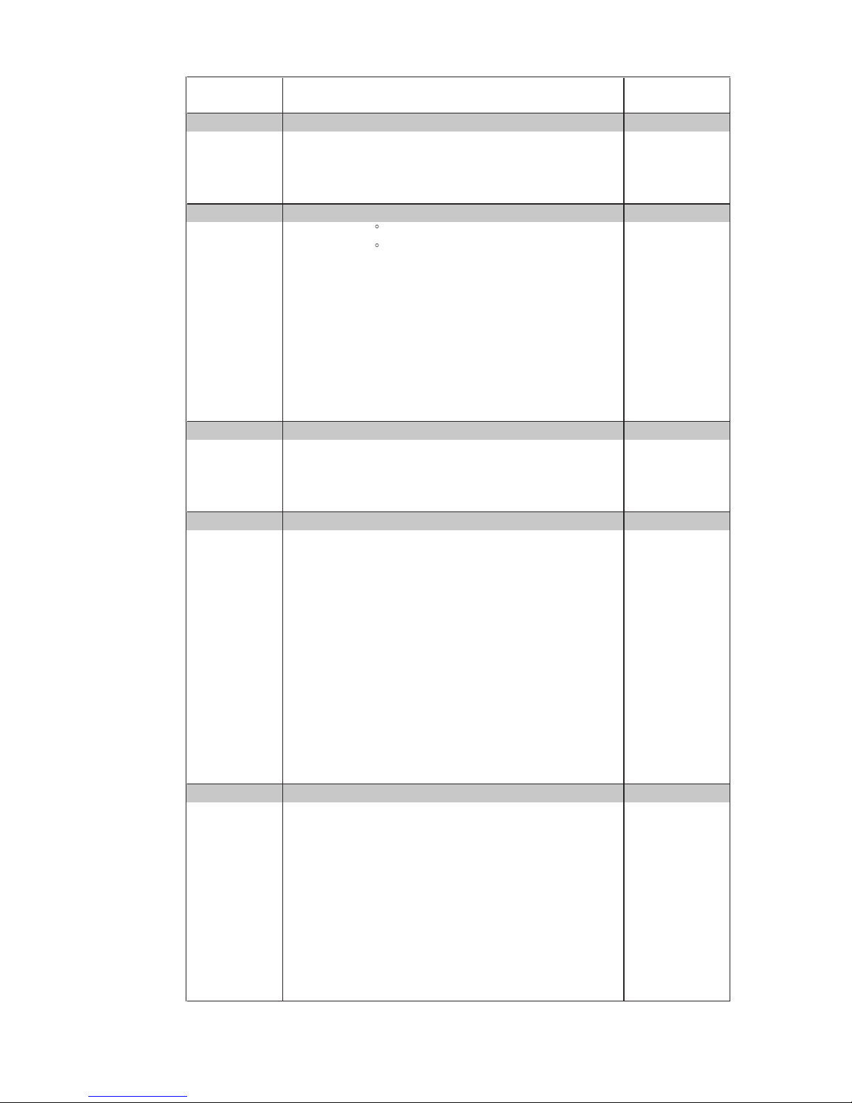
CALL PREMIUM
OUT DESCRIPTION BRONZE
B BURNER TRAY
1-B Burner Tray w/Burners (Sea Level)* 004688F
2-B Burner 301210/4
3-B Burner Orifice Nat. #52 (Sea Level)* 350081F/4
Burner Orifice Pro. #62 (Sea Level)* 350086F/4
C CONTROLS
1-CHigh Limit 135 F 600889B
2-CHigh Limit 140 F 600890B
3-C Thermostat Control MV (Mechanical) 003346F
8-C Thermostat Control MV (Solid State) 005391F
5-C PC Board 005089B
6-C Potentiometer 005087B
7-C Te mperature Sensor 005088B
9-C Thermostat Control IID (Solid State) 005390F
4-C PC Board 005086B
6-C Potentiometer 005087B
7-C Te mperature Sensor 005088B
GGAS VALVE
1-G Combination Valve Nat. MV 003898F
Combination Valve Pro. MV 003899F
Combination Valve Nat. IID 003900F
Combination Valve Pro. IID 004306F
HHEAT E XCHANGER
1-HHeat Exchanger Assy. (Complete) 004694F
2-HHeader/Tubed Kit 004695F
3-H Baffle Kit 004715F
14-H U.G. Assy 002546F
4-H Unitherm Governor 600885
5-H U. G. Cap 400734
6-H U. G. Spring 850247
10-H U. G. Gasket 800276
7-HDrain Valve 500719
8-H Sensor Well 007211F
9-H Bulb Retainer clip 300203
13-H Bypass Baffle 306079
11-H Inlet/Outlet Flange 002432F
12-H Flange Gasket 800013B
M MISCELLANEOUS COMPONENTS
1-M Pressure Switch 062237B
2-M Pressure Switch Tube Assy. 003543F
3-M Thermostat Knob 006885F
4-M Knob Stop 006886F
5-MDial Plate MV 900741
Dial Plate IID 900742
6-M Transformer (IID Unit) 006736F
le Switch 650595
7-M
Togg
8-M Wire Harness MV 004010F
Wire Harness IID 004011F
9-M Thermal Fuse 008126F
*For altitudes above 2,000 feet above sea level, consult the factory.
33
Page 34

CALL PREMIUM
OUT DESCRIPTION BRONZE
P PILOT
1-P Pilot Nat. MV 600525B
Pilot Pro. MV 600575B
3-P Pilot Nat. IID 002003F
Pilot Pro. IID 002003F
5-P Pilot Orifice Nat. MV 003901F
Pilot Orifice Pro. MV 003902F
7-P Pilot Orifice Nat. IID 003903F
Pilot Orifice Pro. IID 004308F
9-P Pilot Generator MV 600019B
11-P Ignition Control IID Nat. 004817B
Ignition Control IID Pro. 004818B
12-P Pilot Mounting Bracket MV 004716F
13-P Pilot Mounting Bracket IID 004717F
Pilot Tube 004078F
15-P Hi Tension Wire IID 002654B
Hi Tension Wire w/Pilot Electrode 007864F
R REFRACTORY
1-RRefractory Block Kit 003544F
SSHEETMETAL
1-SJacket Top 002525F
2-S Flue Collector 002530F
3-S Door Assy. 004689F
4-S Upper Jacket Control Panel 003791F
5-S Wiring Box 306094
6-S Poolstat Lock Box Cover 006492
VVENTING
1-V Stackless To p (Outdoor) 003709
2-V Drafthood (Indoor) 003722
CONVERSION KITS**
Gas Conversions
Nat. to Pro. MV Units 004696B
Pro. to Nat. MV Units 004697B
Nat. to Pro. IID Units NA
Pro. to Nat. IID Units NA
** Gas Conversions are to be done only by a qualified agency.
34
Page 35

35
Page 36

 Loading...