


Installation instructions and User guide
Induction cooktop
VECTI365 models
Instructions d’installation et Guide d’utilisation
Plaque de cuisson à induction
Modèles VECTI365

2

Your safety is important to us. Please read this information before using your cooktop.
3
Installation
WARNING!
Electrical Shock Hazard
Disconnect the appliance from the mains electricity supply before carrying
out any work or maintenance on it.
Connection to a good earth wiring system is essential and mandatory.
Alterations to the domestic wiring system must only be made by a qualified
electrician.
Failure to follow this advice may result in electrical shock or death.
WARNING!
Cut Hazard
Take care - panel edges are sharp.
Failure to use caution could result in injury or cuts.
IMPORTANT SAFETY INSTRUCTIONS
Read these instructions carefully before installing or using this product.
Save these instructions for the local electrical inspector’s use.
Please make this information available to the person responsible for installing your cooktop,
as it could reduce the installation costs.
Please leave these instructions with the appliance. Inform the customer to retain for future
reference.
This appliance is to be installed and connected to the electricity supply only by a qualified
technician in compliance with national codes, local regulations and according to these
instructions.
Electrical installation (including electrical grounding) must be done in accordance with the
National Electrical Code, ANSI/NFPA70 – latest edition and/or local codes. In Canada: Electrical
installation must be in accordance with the current CSA C22.1 Canadian Electrical Codes Part 1
and/or local codes.

IMPORTANT SAFETY INSTRUCTIONS
4
Failure to install the appliance correctly could invalidate any warranty or liability claims.
For personal safety, this appliance must be properly grounded.
Do not leave packaging elements (e.g. plastic bags, polystyrene foam, staples, packing straps)
within easy reach of children during or after installation, as these may cause serious injury.
Make sure you recycle the packaging material.
Before disposing of any appliance, make sure that it can no longer be used and that all hazardous
parts are removed or made harmless, so that children playing with the old appliance cannot
harm themselves.
Only genuine replacement parts may be used for servicing the appliance. These are available
from your nearest Authorized Service Center.
To eliminate the risk of burns or fire by reaching over heated surface units, cabinet storage space
located above the surface units should be avoided. If cabinet storage is to be provided, the risk
can be reduced by installing a rangehood that projects horizontally a minimum of 5 inches
beyond the bottom of the overhead cabinets.

Operation and maintenance
5
Electrical Shock Hazard
Do not cook on a broken or cracked cooktop. If the cooktop should break or
crack, cleaning solutions and spillovers may penetrate it and create a risk of
electrical shock. Contact a qualified technician immediately.
Failure to follow this advice may result in death or electrical shock.
Health Hazard
However, persons with cardiac pacemakers or other electrical implants (such
as insulin pumps) must consult with their doctor or implant manufacturer
before using this appliance to make sure that their implants will not be
affected by the electromagnetic field.
Failure to follow this advice may result in death.
WARNING!
WARNING!
WARNING!
Cut Hazard
The razor-sharp blade of a cooktop scraper is exposed when the safety cover
is retracted. Use with extreme care and always store safely and out of reach
of children.
Failure to use caution could result in injury or cuts.

Operation and maintenance
6
Fire Hazard
Never leave the appliance unattended when in use. Boilover causes smoking
and greasy spillovers that may ignite.
Failure to follow this advice may result in overheating, burning, and injury.
Hot Surface Hazard
DO NOT TOUCH SURFACE UNITS OR AREAS NEAR UNITS – Surface units may
be hot even though they are dark in color. Areas near surface units may
become hot enough to cause burns. During and after use, do not touch, or
let clothing or other flammable materials contact surface units or areas near
units until they have had sufficient time to cool. Among these areas are the
glass surfaces within and around the circles.
Never leave metal objects (such as kitchen utensils) or empty pans on the
cooktop as they can become hot very quickly.
Beware: magnetisable metal objects worn on the body may become hot in
the vicinity of the cooktop. Gold or silver jewellery will not be affected.
Keep children away.
Handles of saucepans may be hot to touch. Check saucepan handles do not
overhang other cooking zones that are on. Keep handles out of reach of
children.
Failure to follow this advice could result in burns and scalds.
WARNING!
WARNING!

Operation and maintenance
7
IMPORTANT SAFETY INSTRUCTIONS
Proper install
technician.
Never use your appliance for warming or heating the room.
Do not leave children alone — Children should not be left alone or unattended in the area where
the appliance is in use. They should never be allowed to sit or stand on any part of the appliance.
Wear proper apparel — Loose-fitting or hanging garments should never be worn while using the
appliance.
User servicing — Do not repair or replace any part of the appliance unless specifically
recommended in the manual. All other servicing should be referred to a qualified technician.
Storage in or on appliance — Flammable materials should not be stored in an oven or near
surface units.
Do not use water on grease fires — Smother fire or flame or use dry chemical or foam-type
extinguisher.
Use only dry potholders — Moist or damp potholders on hot surfaces may result in burns from
steam. Do not let potholder touch hot heating elements. Do not use a towel or other bulky cloth.
Use proper pan size — This appliance is equipped with one or more surface units of different size.
Select utensils having flat bottoms large enough to cover the surface unit heating element. The
use of undersized utensils will expose a portion of the heating element to direct contact and may
result in ignition of clothing. Proper relationship of utensil to burner will also improve efficiency.
Never leave surface units unattended at high heat settings – Boilover causes smoking and greasy
spillovers that may ignite.
Utensil handles should be turned inward and not extend over adjacent surface units — To reduce
the risk of burns, ignition of flammable materials, and spillage due to unintentional contact with
the utensil, the handle of a utensil should be positioned so that it is turned inward, and does not
extend over adjacent surface units.
Do not cook on broken cooktop — If cooktop should break, cleaning solutions and spillovers may
penetrate the broken cooktop and create a risk of electric shock. Contact a qualified technician
immediately.
Clean cooktop with caution — If a wet sponge or cloth is used to wipe spills on a hot cooking
area, be careful to avoid steam burn. Some cleaners can produce noxious fumes if applied to a
hot surface.
ation — Be sure your appliance is properly installed and grounded by a qualified

Operation and maintenance
8
IMPORTANT SAFETY INSTRUCTIONS
CAUTION - Do
climbing on the appliance to reach items could be seriously injured.
If the appliance is malfunctioning, it will display an alert code: first note down the alert code (see
section ‘Alert codes’ in this manual), then contact your Authorized Service Center or Customer
Care to arrange for service. Do not use your appliance until it has been repaired by an authorized
technician.
Never use your appliance as a work or storage surface.
Never leave any objects or utensils on the appliance.
Do not place or leave any magnetizable objects (eg credit cards, memory cards) or electronic
devices (eg computers, MP3 players) near the appliance, as they may be affected by its
electromagnetic field.
We recommend using plastic or wooden kitchen utensils for cooking with your induction cooktop.
Do not place or leave aluminum foil on the cooktop.
After use, always turn off the cooking zones as described in this manual (ie by using the touch
controls). Do not rely on the pan detection feature to turn off the cooking zones when you remove
the pans.
Children or persons with a disability which limits their ability to use the appliance should have a
responsible and competent person to instruct them in its use. The instructor should be satisfied
that they can use the appliance without danger to themselves or their surroundings.
Do not use a steam cleaner to clean your cooktop.
Do not place or drop heavy objects on your cooktop.
Do not stand on your cooktop.
Do not use pans with jagged edges or drag pans across the ceramic glass surface as this can
scratch the glass.
Do not use scourers or any other harsh/abrasive cleaning agents to clean your cooktop, as these
can scratch the ceramic glass.
Do not operate your cooktop by means of an external timer or separate remote control system.
not store items of interest to children in cabinets above an appliance - children

Installation instructions
9
Cooktop and cutout dimensions
C
B
D
G
F
Electrical connection is
made on the right hand
underside of the chassis
A
E
H
Cooktop and cutout dimensions (inches (mm))
overall width of cooktop
A
overall depth of cooktop
B
height of chassis below top of counter (incl. height of conduit junction)
C
width of chassis
D
depth of chassis
E
overall width of cutout
F
overall depth of cutout
G
thickness of countertop*
H
(to enable the cooktop to be fastened with the supplied clamps)
* If the countertop is thicker than 1 ⁄” (40mm), recess its underside to within the thickness range ‘H’
35 ⁄” (900)
20 ⁄” (530)
4 ⁄” (110)
34 ¼ ” (870)
19 ⁄” (503)
34 ⁄” (875)
20 ⁄” (510)
min. 1 ⁄” (30)-
max 1 ⁄” (40)
.

Clearance and cabinetry dimensions
10
F
A
E
D
C
H
C
J
G
WARNING!
B
This cooktop requires
adequate supply of fresh,
cool air to fully function.
The base of the cooktop
must have direct
unrestricted ventilation to
the room where the
cooktop is installed. Follow
the requirements below.
I
Clearance and cabinetry dimensions (inches (mm))
minimum clearance from rear edge of cutout to:
A
nearest combustible surface
minimum clearance from glass surface to:
overhead cabinet centered above the cooktop (unprotected)*
B
overhead cabinet centered above the cooktop (protected)*
minimum clearance from side edges of cutout to:
C
nearest combustible surface 3 ⁄” (80)
minimum distance from front edge of cutout to:
D
front edge of counter 1⁄” (35)
minimum clearance from countertop to:
E
overhead cabinet not directly above the cooktop
minimum distance between cabinets either side of the cooktop
F
maximum depth of overhead cabinetry
G
minimum clearance below top of countertop to:
top of oven installed below cooktop (see Fig.1 and Note #3 following)
H
top of drawer or other obstruction below cooktop (see Fig.2)
maximum distance from right edge of cutout to center of junction box
I
minimum clearance below top of countertop to junction box
J
* See Notes #1 and #2 following.
** This is to allow for adequate slack in the 4’ conduit tted on the cooktop.
2 ⁄” (55)
30 ” (762)
24 ” (610)
18” (457)
36” (915)
13” (330)
4¾ ” (120)
4¾ ” (120)
30” (762)
9” (230)

Clearance and cabinetry dimensions cont.
11
Notes:
#1 To eliminate the risk of burns or fire by reaching over heated surface units, cabinet storage space
located above the surface units should be avoided. If cabinet storage is to be provided, the risk
can be reduced by installing a rangehood that projects horizontally a minimum of 5 “ (127 mm)
beyond the bottom of the cabinets.
#2 B=30” (762 mm) minimum clearance between the top of the cooking surface and the bottom of
an unprotected wood or metal cabinet; or B=24” (610 mm) minimum when bottom of wood or
metal cabinet is protected by not less than ¼-inch-thick flame-retardant millboard covered with
not less than No. 28 MSG sheet steel, 0.015-inch-thick stainless steel, 0.024-inch-thick aluminum,
or 0.020-inch-thick copper.
#3 The oven installed below the cooktop MUST have a cooling fan.
H
Oven with
cooling fan
19⁄” x 2”
(500 x 50 mm)
Fig. 1 Minimum clearances and ventilation
requirements - oven installed below cooktop
H
⁄”(4 mm)
Top of drawer or
other obstruction
19⁄” x ⁄”
(500 x 10 mm)
Fig. 2 Minimum clearances and ventilation
requirements - drawer or other obstruction below
⁄”(4 mm)
19⁄” x ⁄”
(500 x 10 mm)

Before you install the cooktop, make sure that
12
the countertop is square and level, and no structural members interfere with space requirements
the countertop is made of a heat-resistant material
the cooktop will not be installed directly above a dishwasher, fridge, freezer, washing machine or
clothes dryer, as the humidity may damage the cooktop electronics
if the cooktop is installed above an oven, the oven has a built-in cooling fan (see Fig.1)
the installation will comply with all clearance requirements and applicable standards and
regulations
you check that the cooktop is not damaged after unpacking it. If you suspect that it is damaged,
do not install the cooktop. Contact the dealer you purchased the cooktop from.
you read these instructions fully and carefully before beginning to install the appliance
you do not remove any permanently affixed labels, warnings or plates from the appliance. Doing
so may void the warranty
you switch the power off at the service panel and lock the panel to prevent the power from
being switched on accidentally.
the junction box will be easily accessible with the cooktop installed
you consult local building authorities and by-laws if in doubt regarding installation
you use heat-resistant and easy-to-clean finishes (such as ceramic tiles) for the wall surfaces
surrounding the cooktop.
When you have installed the cooktop, make sure that
the connection through conduit is not accessible through cupboard doors or drawers
the power supply cables of other appliances installed nearby cannot come into contact with the
cooktop
there is adequate flow of fresh air from outside the cabinetry to the base of the cooktop.
You may ventilate from adjacent cupboards, but ensure that the available air supply will not be
restricted.
there is adequate slack in the conduit to allow for servicing
the junction box remains accessible with the cooktop installed
you complete the ‘Final checklist’ at the end of these installation instructions.

Flush mounting installation
13
(not recommended)
WARNING!
We do not recommend flush
mounting and sealing as servicing
requires the cooktop to be
removed from the countertop. The
owner carries all risk for flush
mounting the cooktop. The owner
must ensure the cooktop has been
cu t out from the countertop before
servicing can be carried out. The
manufacturer will not be liable for
any costs associated with
removing or replacing a flushmounted and/or sealed-in product,
nor for repairing any damage that
may be incurred by doing this.
Electrical connection is
made at the right rear
C
B
D
A
E
J
G
F
F
I
I
G
G
F
I
Cooktop and cutout dimensions (inches (mm))
H
overall width of cooktop
A
overall depth of cooktop
B
height of chassis below top of counter (incl. height of conduit junction)
C
width of chassis
D
depth of chassis
E
overall width of routered recess
F
I
overall width of cutout
F
overall depth of routered recess
G
I
overall depth of cutout
G
corner radius of routered recess
H
height of routered recess
I
thickness of countertop*
J
(to enable the cooktop to be fastened with the supplied clamps)
* If the countertop is thicker than 1 ⁄” (40mm), recess its underside to within the thickness range ‘H’.
35 ⁄” (900)
20 ⁄” (530)
4 ⁄” (110)
34 ¼ ” (870)
19 ⁄” (503)
35 ⁄” (905)
34 ⁄” (875)
21 ⁄” (535)
20 ⁄” (510)
max. ⁄” (2)
⁄” (5)
min. 1 ⁄” (30)-
max 1 ⁄” (40)

Flush mounting installation (not recommended)
14
Important!
For any clearance or other installation requirement not specified separately for flush mounting
installation, details in the previous section (recommended method of installation) apply.
STEP 1
5 mm
STEP 2
Fitting the rear clamps
21
Securing the rear clamps Securing the front clamps
Clamp
Seal Seal
Screw
Clamp
Screw
32
16
/ " (20 mm) min.
9
25
1 / " (40 mm) max.
32
16
/ " (20 mm) min.
9
25
1 / " (40 mm) max.

Flush mounting installation (not recommended)
min. 150 OC rated
15
Important!
For any clearance or other installation requirement not specified separately for flush mounting
installation, details in the previous section (recommended method of installation) apply.
STEP 3
STEP 4
Ensure silicone does
not leak underneath glass.
Apply tape/foam
inside recess to stop
silicone leaking underneath.

STEP 5
16
STEP 6
TO REMOVE PRODUCT
2
1

Additional electrical requirements
17
Electrical installation must be carried out only by a licensed electrician.
The cooktop MUST be connected to the proper electrical voltage and frequency as specified:
Model - VECTI365
Rated power - 11.5kW (10kW)
Required power supply - 240V~, 48A, 60Hz (208V~, 48A, 60Hz)
This appliance must be connected to a grounded, metallic permanent wiring system or a
ground connector should be connected to the ground terminal or wire lead on the cooktop.
This appliance is manufactured with a frame-connected, green or bare ground wire. Connect the
cooktop cable to the junction box through the CSA or UL-listed conduit connector. Complete
electrical connection according to local codes and ordinances.
Warning: improper connection of aluminum house wiring to copper leads can result in an
electrical hazard or fire. Use only connectors designed for joining copper to aluminum and
follow the manufacturer’s recommended procedure.
Connect the cooktop with copper wire only.
The flexible (4’) armored cable should be connected directly to the junction box.
Do not cut the conduit.
A CSA or UL-listed conduit must be provided at the junction box.
Do not ground to a gas pipe.
Do not have a fuse in the grounding or neutral circuit.
A time delay fuse or circuit breaker is recommended.
Connect directly to the fused disconnect (or circuit breaker box) through flexible, armored or
non-metallic sheathed, copper cable (with grounding wire).
If codes permit and a separate grounding wire is used, it is recommended that a qualified
electrician determine that the grounding path and wire gauge are in accordance with local
codes.

Connecting the cooktop to the power supply
18
The nameplate label is located on the underside of the cooktop, on the right hand side. See Fig.
5 below.
If the appliance is to be completely enclosed in a cabinet, feed the appliance cable through the
opening in the cabinet.
1
Disconnect the power supply.
2
Remove the junction box cover.
3
Connect the cooktop cable to the junction box through the CSA or UL-listed conduit connector.
4
Connect the two black wires together with twist-on connectors.
5
Connect the two red wires together with twist-on connectors.
6
Connect electrical connection according to local codes and ordinances.
If local codes PERMIT connecting the cabinet-grounding connector to the neutral (white)
wire in the junction box:
7a
Connect the green cooktop cable wire to the neutral (white) wire in the junction box (Fig. 3).
8a
Replace the junction box cover.
OR If local codes DO NOT PERMIT connecting the cabinet-grounding connector to the
neutral (white) wire in the junction box:
7b
Terminate the neutral (white) wire in the junction box (Fig. 3).
8b
Connect the green grounding cooktop cable wire to a grounded wire in the junction box.
9b
Replace the junction box cover.
OR If connecting to a four-wire electrical system:
7c
Terminate the neutral (white) wire in the junction box (Fig. 4).
8c
Connect the green cooktop cable wire to the green grounding wire in the junction box (Fig. 4).
9c
Replace the junction box cover.
Junction box
Red wires
3-wire cable from
power supply
Black wires
Junction box
Red wires
4-wire cable from
power supply
White wire
White
wire
Green & yellow
wire
CSA or UL-listed
conduit connector
Fig. 3 Electrical connection to
a three-wire electrical system
to appliance
Green & yellow
wires
Black wires
CSA or UL-listed
conduit connector
to appliance
Fig. 4 Electrical connection to a
four-wire electrical system
Fig. 5 Location of nameplate label

Fastening the cooktop to the counter
19
1
Turn the cooktop upside down and place it on a soft surface.
2
Spread the seal around the edges of the cooktop with the adhesive side facing down, as shown
in Figs. 6 and 7. Make sure that the whole perimeter is sealed. Cut off any excess material.
3
Mount the supplied clamps and screws onto the cooktop, as shown (without tightening the
screws) if not already fitted.
4
Place the cooktop into the cutout, then tighten the screws to clamp the cooktop securely to the
counter.
5
Using a sharp cutter or trimmer knife, trim the excess sealing material around the edge of the
cooktop. Take care not to damage the countertop.
Note: if the countertop is thicker than 1 ⁄” (40 mm), recess the underside to between
1
⁄” (30 mm) and 1 ⁄” (40 mm).
Front
Rear
Seal
Adhesive side
Clamp position
Fitting the rear clamps
Fig. 6 Preparing the cooktop before installation
21
Securing the rear clamps Securing the front clamps
Clamp
Seal Seal
Screw
Clamp
Screw
32
16
/ " (20 mm) min.
9
25
1 / " (40 mm) max.
Fig. 7 Fastening the cooktop to the counter
32
16
/ " (20 mm) min.
9
25
1 / " (40 mm) max.

Final checklist
20
TO BE COMPLETED BY THE INSTALLER
Is the cooktop grounded?
Check that there is an adequate and constant flow of fresh air from outside the cabinetry to the
base of the cooktop.
Check that the connection through conduit is not accessible via cupboard doors or drawers.
Is the cooktop clamped down securely?
Make sure the cooktop is clean and free from any debris. Wipe with a clean damp cloth if
necessary.
Check that the pan detection feature is working correctly. Turn on each cooking zone without
putting any cookware on them. Are all the ‘No pan’ indicators
Check that all the cooking zones function correctly. Place suitable pans with water in them on
each zone, then turn all of them on to a high setting. Is the water heating?
Are all touch controls and indicators functioning?
To check that the ‘Hot surface’ indicators function correctly, keep heating the water on all the
zones until all the ‘Hot surface’ indicators
surface’ indicators still glowing?
Have you shown the customer how to use the cookop? Make sure you explain to the customer
about:
the importance of taking note of the safety warnings at the beginning of this manual,
especially for persons with cardiac pacemakers or other electrical implants
the ‘Hot surface’ indicators
using smooth-based, induction-suitable cookware only
the pan detection feature.
light up, then turn off all the zones. Are all the ‘Hot
glowing?
Installer’s name:
Installer’s signature:
Installation company:
Date of installation:
LEAVE THESE INSTRUCTIONS WITH THE CUSTOMER

Introduction
21
Introducing your cooktop
Congratulations on your new purchase. Your induction cooktop is the ultimate in induction
cooking, giving you the speed, precision, and simplicity of electronic control, and the easy-care
elegance of a ceramic glass surface. For more information, visit our local website listed on the
back cover.
A word on induction cooking
Induction cooking is a safe, advanced, efficient, and economical cooking technology. It works by
electromagnetic vibrations generating heat directly in the pan, rather than indirectly through
heating the glass surface. The glass becomes hot only because the pan eventually warms it up.
This technology has a number of advantages over traditional radiant energy cooking:
Heat-up times are much faster.
Use is safer as no heating takes place unless a suitable pan is placed on the cooking zone.
As heat is transferred without loss, you save energy.
Before using your new cooktop
Read this guide, taking special note of the ‘Safety and warnings’ section.
Make sure the cooktop is clean and free from any debris. Wipe with a clean damp cloth if
necessary.
Using the touch controls
The controls respond to touch, so you don’t need to apply any pressure.
Use the ball of your finger, not its tip.
You will hear a beep each time a touch is registered.
Make sure the controls are always clean, dry, and there is no object (eg a utensil or a cloth)
covering them. Even a thin film of water may make the controls difficult to operate.
Fig.8 Use the ball of your finger, not its tip

1
22
4
3
2
1
2300 (3200W*) zone
2
1400 (1800W*) zone
3
2400 (3700W*) zone
4
1850 (2500W*) zone
5
Touch controls and
indicators
11
7
10
6
ON-OFF ON-OFF ON-OFF
ON-OFF ON-OFF
* Maximum power output
when set for PowerBoost.
See ‘Using the PowerBoost
feature.’
8
12
4
5
6
ON/OFF control
7
ON/OFF indicator
8
‘No pan’ indicator
9
‘Hot surface’ indicator
10
Heat setting control (decrease)
11
Heat setting control (increase)
12
Heat setting indicators (‘crescent’)
13
PowerBoost indicator
Fig.9
9
Fig.10 Touch controls and indicators for a
cooking zone (layouts vary)
13

Choosing the right cookware
23
Important!
Only use cookware with a smooth base suitable for induction
cooking. Look for the induction symbol on the packaging or the
bottom of the pan.
You can check whether your cookware is suitable by carrying out
a magnet test. Move a magnet towards the base of the pan. If it is
attracted, the pan is suitable for induction.
If you do not have a magnet:
1
Put some water in the pan you want to check.
2
Follow the steps under ‘To start cooking’ opposite.
3
If the ‘No pan’ indicator does not glow and the water is heating, the pan is suitable.
Cookware made from the following materials is not suitable: pure stainless steel, aluminum or
copper without a magnetic base, glass, wood, porcelain, ceramic, earthenware.
Do not use cookware with jagged edges or a curved base.
23
Make sure that the base of your pan is smooth, sits flat against the glass, and is the same or
similar size as the cooking zone. Always center your pan on the cooking zone.
Always lift pans off the cooktop– do not slide, or they may scratch the glass.
Using your induction cooktop
24
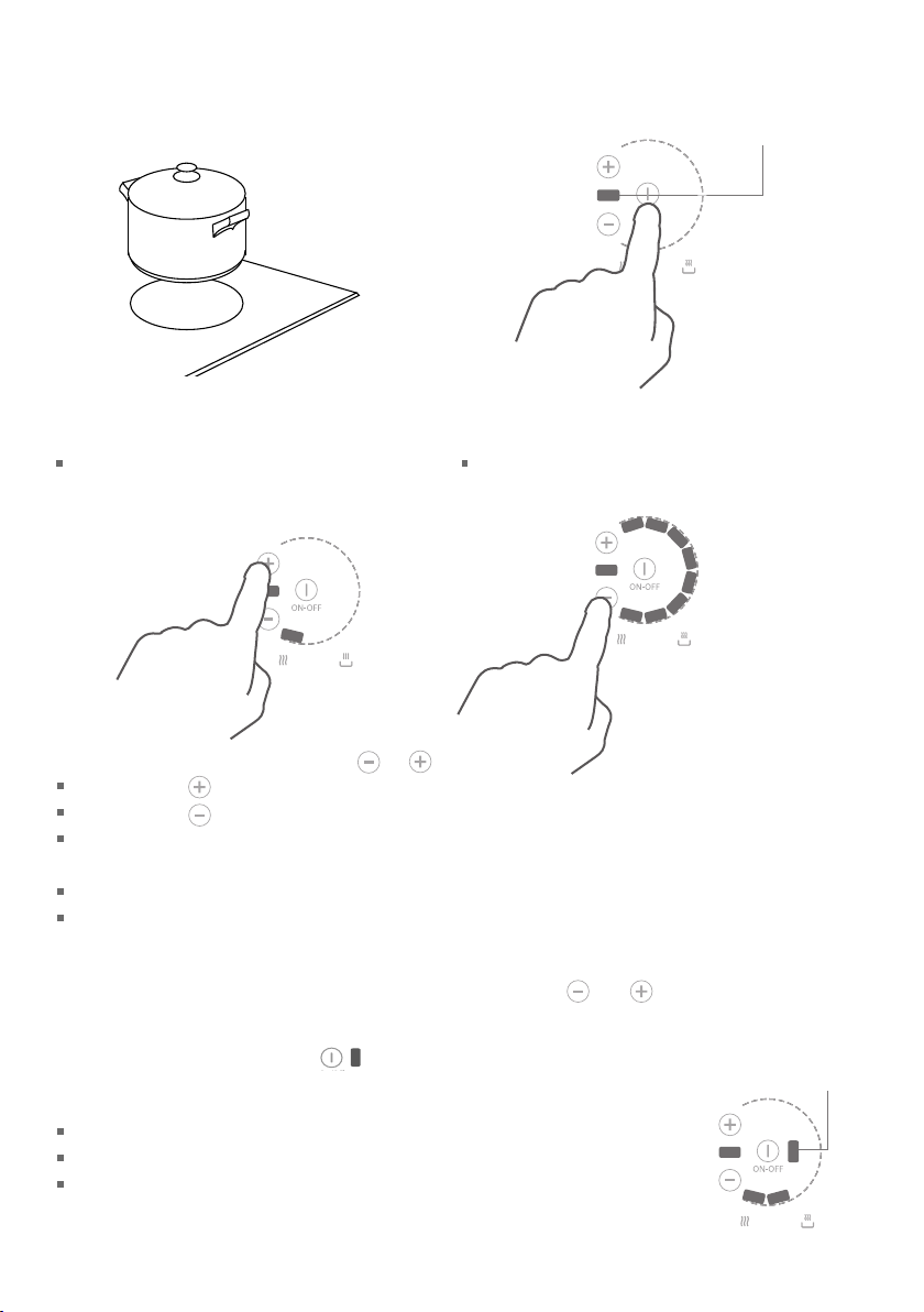
To start cooking
1
Place a suitable pan on the
cooking zone you wish to use.
Make sure the bottom of the pan
and the surface of the cooking
zone are clean and dry.
2
Touch the ON/OFF control of the
cooking zone.
The ON/OFF indicator will glow.
ON/OFF indicator
OR
3
Select a heat setting by touching or .
If you touch , you will start out at the lowest heat setting (1).
If you touch , you will start out at the highest heat setting (8).
The number of indicators in the ‘crescent’ corresponds to the heat setting
(eg two indicators = heat setting 2).
You can modify the heat setting at any time during cooking.
If you don’t choose a heat setting within 10 seconds, the cooking zone will automatically turn
off. Start from step 2 again.
Tip: to clear a cooking zone’s heat setting quickly, touch its
do not select a new heat setting within 10 seconds, the cooking zone will automatically turn off.
and controls together. If you
If the ‘No pan’ indicator glows
‘No pan’ indicator
This means that:
you have not placed a pan on the correct cooking zone or
the pan you’re using is not suitable for induction cooking or
the pan is too small or not properly centered on the cooking zone.
No heating takes place unless there is a suitable pan on the cooking zone.
The cooking zone will automatically turn off after 30 seconds if no suitable pan is placed on it.

When you have finished using a cooking zone
25
Turn the cooking zone off by touching its ON/OFF control. Make sure that the cooking zone’s
ON/OFF indicator is unlit.
When you have finished using the cooktop
Make sure that you have turned off all cooking zones (all the ON/OFF indicators should be unlit).
Beware of hot surfaces
‘Hot surface’ indicator
A glowing ‘Hot surface’ indicator will show which cooking zone is too hot to touch. It will go out
when the surface has cooled down to a safe temperature.

Using the PowerBoost feature
26
This feature enables you to sear meat or bring liquid to the boil very quickly. When a cooking
zone is set for PowerBoost, it uses more than 100% of the power of that particular cooking zone,
resulting in a boost of intense heat.
Important!
Beware: PowerBoost heats food and liquids very quickly. Do not leave the cooktop unattended.
To set a cooking zone for PowerBoost
ON-OFF
1
Turn the cooking zone on.
2
Set the cooking zone to the highest heat
setting (8), then release the touch control.
3
Touch the control of the cooking zone.
The PowerBoost indicator will glow, indicating that the cooking zone is now set for PowerBoost.
Unless you quit the PowerBoost setting sooner, the cooking zone will be on PowerBoost (more
than 100%) for 10 minutes, and then automatically reduce the heat to setting 8 (100 %).
To quit the PowerBoost setting
Touch the control of the cooking zone at any time and select a new setting or turn the
cooking zone off.
PowerBoost indicator

Note:
27
You can set a maximum of three cooking zones for PowerBoost at any one time, as long as one is
not behind the other. For example:
When a cooking zone is set for PowerBoost, the cooking zone immediately in front of or behind
it may have to reduce its power level.

Cooking guidelines
28
Important!
Never leave the appliance unattended when in use. Boilover causes smoking and greasy
spillovers that may ignite.
Take care when deep-frying: oil or fat can overheat very quickly, particularly on a high setting.
General cooking tips
Using a lid will reduce cooking times through retaining the heat.
Minimize the amount of liquid to reduce cooking times.
Start cooking on a high setting and reduce it when the food has come to the boil or heated
through.
Cooking rice, simmering
Some tasks, including cooking rice by the absorption method, may require a setting higher than
the lowest setting to ensure the food is cooked properly in the time recommended.
Simmering occurs below boiling point, when bubbles are just rising occasionally to the surface
of the cooking liquid. It’s the key to delicious soups and tender stews because the flavors
develop without overcooking the food. Egg-based sauces are best kept below boiling point
throughout cooking, and flour-based sauces should also be gently simmered after they have
reached boiling point.
Searing steak
1
Stand the meat at room temperature for about 20 minutes before cooking.
2
Heat up a smooth-based skillet. Enamelled cast iron will give you the best results.
3
Brush both sides of the steak with oil and season it to taste.
4
Lower the meat onto the hot skillet.
5
Turn the steak only once during cooking. The exact cooking time will depend on the thickness
of the steak and how cooked you want it. Times vary between 2 to 8 minutes per side. Press the
steak to gauge how cooked it is: the firmer it feels, the more ‘well done’ it will be.
6
Leave the steak to rest on a warm plate for a few minutes to allow it to relax and become tender
before serving.

Heat settings
29
The settings below are guidelines only. The exact setting will depend on several factors,
including your cookware and the amount you are cooking. Experiment with the cooktop to find
the settings that best suit your needs. In general, the lower heat settings offer a more gradual
control, whereas the higher heat settings have a more pronounced step change in power.
100
80
60
40
20
Percentage of power %
0
12345678
Heat setting
Heat setting
1-2
2-3
3
-
4
5
-
6
6-7
8
(PowerBoost))
(
Note: the settings and suitability shown are subject to variability due do differences in cookware construction.
delicate warming for small amounts of food
melting chocolate, butter, and foods that burn quickly
slow cooking
gentle simmering
cooking rice
rapid simmering
pancakes
sautéing
cooking pasta
stir-frying
searing
boiling water
Suitable for

Care and cleaning
30
Important!
Do not use a steam cleaner to clean your cooktop.
Do not use scourers or any harsh/abrasive cleaning agents to clean your cooktop, as these can
scratch the ceramic glass.
What?
soiling examples
Light soiling after
every use
fingerprints and
marks
stains left by
nonsugary liquids (eg
water, soup, oil)
Non-sugary
boilovers, spills and
food stains
burnt-on food or
grease
pasta water, milk,
soup
Hot sugary spills,
melted plastic or metal
sugar, sugary syrups
jams and jellies
vegetables or
vegetable water
with high sugar
content (peas,
sweetcorn, beet)
melted aluminum
foil or plastic wrap
Spill on the touch
control area
pasta water, milk,
soup
How? Important!
1 Wipe with a soft, damp
cloth and mild detergent. A
microfiber or ‘glass’ cloth is ideal
for this.
2 Wipe dry with a clean cloth or
paper towel.
1 Remove the soiling with
ceramic cooktop cleaner using a
sponge or non-abrasive scourer
suitable for ceramic glass.
2 Remove any excess cleaner and
wipe dry with a clean cloth or
paper towel.
3 Apply ceramic cooktop
conditioner or protector
following the instructions on
the dispenser. A microfiber or
‘glass’ cloth is ideal for this.
Remove these immediately with a
spatula, frosting knife, or razor
blade scraper suitable for ceramic
glass cooktops, but beware of hot
spills and surfaces:
1 Hold the blade or utensil at a
o
30
angle and scrape the soiling
or spill to a cool area of the
cooktop.
2 Immediately clean the soiling
up with a dish cloth or paper
towel.
3 Follow the instructions for ‘Light
soiling after every use’ above.
1 Soak up the spill.
2 Wipe the touch control area
with a clean damp sponge or
cloth.
3 Wipe the area completely dry
with a paper towel.
Before cleaning, make sure that
the glass is a safe temperature to
touch.
Heavy-duty scourers, some nylon
scourers and harsh/abrasive
cleaning agents may scratch the
glass. Always read the label to
check if your cleaner or scourer is
suitable.
Never leave cleaner residue on the
cooktop: the glass may become
stained.
Remove stains left by melts
and sugary food or spillovers
immediately. If left to cool on
the glass, they may be difficult
to remove or even permanently
damage the glass surface.
Cut hazard: the blade in a scraper
is razor-sharp when the safety
cover is retracted. Use with
extreme care and always store
safely out of reach of children.
The cooktop may beep and turn
itself off, and the touch controls
may not function while there is
liquid on them. Make sure you
wipe the touch control area dry
before turning any cooking zone
back on.

Troubleshooting
31
Troubleshooting chart
Problem Possible causes What to do
None of the cooking
zones can be
turned on.
No power. Make sure the cooktop is
connected to the power supply.
Check whether there is a power
outage in your home or area. If
you’ve checked everything and
the problem persists, call your
Authorized Service Center or
Customer Care.
The touch controls are
difficult to operate.
The glass is being
scratched.
Some or all cooking
zone ‘crescents’ flash
the arrangement
shown below, there is
a continuous beep, and
the cooking zone(s) have
turned off.
+ continuous
beeping
There may be a slight film of water
over the controls or you may be
using the tip of your finger when
touching the controls.
Rough-edged cookware.
Unsuitable, abrasive scourer or
cleaning products being used.
Liquid has spilled onto the touch
control area.
There are objects (eg utensils or
cloths) on the touch control area.
Several touch controls are
registering continuous contact
(eg due to someone resting their
hand on the touch control area).
Make sure the touch control
area is dry and use the ball of
your finger when touching the
controls.
Use cookware with flat and
smooth bases. See ‘Choosing
the right cookware’.
See ‘Care and cleaning’.
See ‘Care and cleaning’ for
instructions.
Remove the object(s) from the
touch control area and touch
any of the cooking zone’s
controls to clear the ‘crescent’
display.
Remove the cause of
continuous contact and touch
any of the cooking zone’s
controls to clear the ‘crescent’
display.

Troubleshooting chart
32
Problem Possible causes What to do
Some pans make
crackling or clicking
noises.
This may be caused by the
construction of your cookware
(layers of different metals
vibrating differently).
This is normal for induction
cookware and does not indicate
a fault.
The cooktop makes a low
humming or hissing
noise when used on
a high heat setting
(especially PowerBoost).
Fan noise coming from
the cooktop.
Pans do not become hot
and the ‘No pan’ indicator
glows.
The PowerBoost indicator
flashes when you are
trying to set PowerBoost.
This is caused by the technology
of induction cooking.
A cooling fan built into
your cooktop has come on
to prevent the electronics
from overheating. It may
continue to run even after
you’ve turned all the cooking
zones off.
The cooktop cannot detect the
pan because it is not suitable for
induction cooking.
The cooktop cannot detect the
pan because it is too small for
the cooking zone or not
properly centered on it.
PowerBoost is temporarily
unavailable because the
cooktop needs to protect
itself from overheating.
This is normal, but the
noise should quieten down
or disappear completely
when you decrease the
heat setting.
This is normal and needs
no action.
Use cookware suitable for
induction cooking. See
section ‘Choosing the right
cookware’.
Center the pan and make
sure that its base matches
the size of the cooking
zone.
Allow the cooktop to cool
down.

Alert codes
33
Your cooktop can self-diagnose any faults and then communicate this information to you as an
alert code.
If there is an electrical malfunction, the cooktop will:
turn one or all cooking zones off
display indicators in the ‘crescent’ of one or more cooking zones.
What to do if an alert code is displayed
Important!
Any code di
These should only be fixed by an authorized technician.
1
Make a note of which cooking zone(s) display an alert code. Check the arrangement of the
glowing ‘crescent ’ indicators.
2
Check the chart following to identify the alert code displayed.
3
Note down the alert code. This information will help your Authorized Service Center or Customer
Care attend to the problem faster.
4
Contact your Authorized Service Center or Customer Care with the alert code information to
arrange service. Refer to the Service & Warranty book for contact details.
splayed indicates an electrical malfunction.
Important!
use the cooktop until the problem has been fixed by an authorized technician.
Do not

Individual cooking zone codes
34
Alert display Alert code
+ continuous beeping
U400
E5
E6
E7
E9
E2

Whole cooktop codes
35
Alert display Alert code
+ continuous beeping
All ‘crescents’
All ‘crescents’
All ‘crescents’
All ‘crescents’
All ‘crescents’
U400
ER31
ER47
ER36
ER39
ER20
All ‘crescents’
ER13
All ‘crescents’
ER22
All ‘crescents’

36

Consignes de sécurité et mises en garde
37
Votre sécurité est importante pour nous. Veuillez lire ces informations avant d'utiliser votre
plaque de cuisson.
Installation
MISE EN GARDE!
Risque de choc électrique
Débranchez l'appareil de l'alimentation électrique avant de procéder à tout
travail d'entretien ou de maintenance sur celui-ci.
La connexion à un système de mise à la terre convenable est essentielle et
obligatoire.
Les modifications au système de câblage domestique doivent être effectuées
uniquement par un électricien qualifié.
Le non-respect de cette consigne peut entraîner un choc électrique ou la
mort.
MISE EN GARDE!
Risque de coupure
Attention, les bords du panneau sont tranchants.
Le non-respect de cette consigne peut causer des blessures ou des coupures.
CONSIGNES DE SÉCURITÉ IMPORTANTES
Lisez attentivement ces instructions avant d'installer ou utiliser ce produit.
Conservez ces instructions pour permettre à l'inspecteur en électricité local de les consulter.
Veuillez remettre ces informations à la personne responsable de l'installation de votre plaque de
cuisson. Elles pourraient aider à réduire les coûts d'installation.
Laissez ces instructions avec l'appareil. Demandez au client de les conserver pour référence
ultérieure.
Cet appareil doit être installé et raccordé à l'alimentation électrique par un technicien qualifié,
en respectant les codes nationaux, les réglementations locales et ces instructions.
L'installation électrique (incluant la mise à la terre électrique) doit être effectuée en conformité
avec le Code national de l'électricité, ANSI/NFPA70– dernière édition, et/ou les codes locaux. Au
Canada : L'installation électrique doit être effectuée en conformité avec la norme CSA C22.1 en
vigueur du Code canadien de l'électricité, Première partie, et/ou les codes locaux.

CONSIGNES DE SÉCURITÉ IMPORTANTES
38
Le fait de ne pas installer l'appareil de façon adéquate pourrait entraîner l'annulation de toute
garantie ou réclamation.
Pour votre sécurité personnelle, cet appareil doit être mis à la terre de façon appropriée.
Gardez les éléments d'emballage (ex. : sacs en plastique, mousse de polystyrène, agrafes,
courroies) hors de la portée des enfants pendant ou après l'installation, car ils pourraient causer
des blessures graves.
Assurez-vous de recycler les matériaux d'emballage.
Avant de mettre un appareil au rebut, veillez à ce qu'il ne soit plus fonctionnel et assurez-vous
de retirer ou rendre inoffensives toutes les pièces dangereuses, de façon à ce que les enfants ne
puissent pas se blesser en jouant avec cet appareil.
Utilisez uniquement des pièces de remplacement authentiques pour effectuer l'entretien ou les
réparations de l'appareil. Vous pouvez vous les procurer auprès d'un Centre de service autorisé
par dans votre région.
Pour réduire les risques de brûlure ou d'incendie, évitez de ranger des objets dans les armoires
situées au-dessus des éléments de surface. Si toutefois vous devez ranger des objets dans ces
armoires, réduisez les risques en installant une hotte dont la partie saillante horizontale dépasse
la partie inférieure des armoires suspendues d'au moins 5po (127mm).
Utilisation et entretien
39
Risque de choc électrique
Ne cuisinez pas sur une plaque de cuisson brisée ou craquée. Lorsqu'une
plaque de cuisson est brisée ou craquée, les solutions de nettoyage et
déversements peuvent pénétrer dans celle-ci et causer un risque de choc
électrique. Contactez immédiatement un technicien qualifié.
Le non-respect de cette consigne peut entraîner un choc électrique ou la
mort.
Risque pour la santé
Toutefois, les personnes possédant un stimulateur cardiaque ou tout autre
implant électrique (tel qu'une pompe à insuline) doivent consulter leur
médecin ou fabricant d'implant avant d'utiliser cet appareil pour s'assurer
que leur implant ne sera pas affecté par le champ électromagnétique.
MISE EN GARDE!
MISE EN GARDE!
Le non-respect de cette consigne peut entraîner la mort.
MISE EN GARDE!
Risque de coupure
La lame très coupante d'un grattoir à plaque de cuisson est exposée lorsque
le couvercle de sécurité est rétracté. Utilisez-la avec beaucoup de prudence,
puis rangez-la toujours de façon sécuritaire, hors de la portée des enfants.
Le non-respect de cette consigne peut causer des blessures ou des coupures.

Utilisation et entretien
40
Risque d'incendie
Ne laissez jamais l'appareil sans surveillance pendant l'utilisation. Les
débordements produisent de la fumée et des déversements de matières
grasses qui peuvent s'enflammer.
Le non-respect de cette consigne peut entraîner une surchauffe, des brûlures
et des blessures.
Risque de surface brûlante
NE TOUCHEZ PAS LES ÉLÉMENTS DE SURFACE OU LES ZONES À PROXIMITÉ
DE CEUX-CI. Les éléments de surface peuvent être brûlants même s'ils
sont d'une couleur foncée. Les zones à proximité des éléments de surface
peuvent atteindre une température suffisamment élevée pour causer des
brûlures. Pendant et après l'utilisation, ne laissez pas les vêtements ou autres
matières inflammables entrer en contact avec les éléments de surface ou les
zones à proximité, et ne les touchez pas avant qu'ils soient refroidis. Parmi les
zones à proximité, évitez les surfaces en verre situées à l'intérieur et autour
des cercles.
Ne laissez jamais d'objets métalliques (tels que des ustensiles de cuisine)
ou des casseroles vides sur la plaque de cuisson car ils pourraient devenir
brûlants très rapidement.
Attention : les objets métalliques magnétisables portés sur le corps peuvent
devenir brûlants lorsqu'ils se trouvent à proximité de la plaque de cuisson.
Les bijoux en or ou en argent ne seront pas affectés.
Gardez les enfants à distance.
Les poignées des casseroles peuvent être brûlantes au toucher. Assurez-vous
de ne pas placer les poignées des casseroles au-dessus des zones de cuisson
activées. Gardez les poignées hors de la portée des enfants.
MISE EN GARDE!
MISE EN GARDE!
Le non-respect de cette consigne peut causer des brûlures et ébouillantages.

Consignes de sécurité et mises en garde
41
Utilisation et entretien
CONSIGNES DE SÉCURITÉ IMPORTANTES
Installation appropriée — Veillez à ce que votre appareil soit correctement installé et mis à la
terre par un technicien qualifié.
N'utilisez jamais votre appareil pour réchauffer ou chauffer une pièce.
Ne laissez jamais les enfants sans surveillance — Ne laissez pas les enfants seuls ou sans
surveillance à proximité de l'endroit où l'appareil est utilisé. Ne les laissez jamais se tenir ou
s’asseoir sur une quelconque partie de l'appareil.
Portez des vêtements convenables— Ne portez pas de vêtements amples ou pendants lorsque
vous utilisez cet appareil.
Entretien par l'utilisateur — Ne réparez ou remplacez aucune pièce de cet appareil, sauf si cela
est spécifiquement recommandé dans le présent document. Tous les autres travaux doivent être
confiés à un technicien qualifié.
Rangement dans l'appareil et sur celui-ci — Ne rangez pas de matières inflammables dans un
four ou à proximité des éléments de surface.
N'essayez pas d'éteindre les feux de friture avec de l'eau— Étouffez le feu ou la flamme, ou
utilisez un extincteur à poudre ou à mousse.
Utilisez uniquement des gants de cuisine secs — N'utilisez pas de gants de cuisine humides ou
mouillés sur les surfaces brûlantes car la vapeur pourrait causer des brûlures. Ne laissez pas les
gants de cuisine toucher les éléments chauffants qui sont brûlants. N'utilisez pas de serviette ou
linge encombrant.
Utilisez des casseroles d'une taille appropriée— Cet appareil est équipé d'un ou plusieurs
éléments de surface de différentes tailles. Utilisez des ustensiles à fond plat suffisamment larges
pour couvrir leur élément chauffant. L'utilisation d'ustensiles de trop petite taille vous expose
à une partie de l'élément chauffant, qui risque alors d'enflammer vos vêtements. De plus,
l'utilisation d'ustensiles adaptés à l'élément chauffant améliore le rendement de l'appareil.
Ne laissez jamais les éléments de surface sans surveillance lorsque vous utilisez des réglages de
chaleur élevés— Les débordements produisent de la fumée et des déversements de matières
grasses qui peuvent s'enflammer.
Tournez les poignées des ustensiles vers l'intérieur, en veillant à ce qu'elles ne soient pas
placées au-dessus des éléments de surface adjacents— Pour réduire les risques de brûlure,
d'inflammation des matériaux inflammables et de déversement résultant d'un contact accidentel
avec les ustensiles, tournez leur poignée vers l'intérieur, en veillant à ce qu'elle ne soit pas placée
au-dessus des éléments de surface adjacents.
Ne cuisinez pas sur une plaque de cuisson endommagée— Lorsqu'une plaque de cuisson est
brisée, les solutions de nettoyage et déversements peuvent pénétrer dans l'appareil endommagé
et causer un risque de choc électrique. Contactez immédiatement un technicien qualifié.
Nettoyez la plaque de cuisson avec précaution — Lorsque vous utilisez une éponge ou un chiffon
humide pour essuyer des déversements sur une surface de cuisson brûlante, assurez-vous d'éviter
les brûlures causées par la vapeur. Certains produits nettoyants peuvent produire des vapeurs
nocives lorsqu'ils sont appliqués sur une surface brûlante.

Utilisation et entretien
42
CONSIGNES DE SÉCURITÉ IMPORTANTES
ON - Ne rangez pas d’articles pouvant attirer les enfants au-dessus d'un appareil. Les
ATTENTI
enfants pourraient se blesser sérieusement en grimpant sur l'appareil pour atteindre ces articles.
L'appareil affiche un code d'erreur lorsqu'il ne fonctionne pas correctement. Notez alors le code
d'erreur (consultez la section ‘Codes d'erreur’ de ce manuel), puis contactez votre Centre de
service autorisé ou l'Assistance à la clientèle pour obtenir une réparation. N'utilisez pas votre
appareil avant qu'il soit réparé par un technicien autorisé.
N'utilisez jamais votre appareil comme surface de travail ou rangement.
Ne laissez jamais d'objets ou d'ustensiles sur l'appareil.
Ne placez ou laissez aucun objet magnétisable (ex. : cartes de crédit, cartes mémoire) ou
appareils électroniques (ex. : ordinateurs, lecteurs MP3) à proximité de l'appareil, car ils
pourraient être affectés par son champ électromagnétique.
Nous vous recommandons d'utiliser des ustensiles de cuisine en plastique ou en bois pour cuisiner
sur votre plaque de cuisson à induction.
Ne placez ou laissez aucun papier d'aluminium sur la plaque de cuisson.
Après l'utilisation, éteignez toujours les zones de cuisson en vous reportant aux instructions de
ce manuel (ex. : en utilisant les réglages tactiles). Ne vous fiez pas sur la fonction de détection de
casserole pour éteindre les zones de cuisson lorsque vous retirez les casseroles.
Les enfants ou les personnes souffrant d'un handicap limitant leur capacité à utiliser l'appareil
doivent se faire expliquer le fonctionnement par une personne responsable et compétente.
L'instructeur doit s'assurer qu'ils pourront utiliser l'appareil sans aucun danger pour leur
personne ou leur entourage.
N'utilisez pas de nettoyeur à vapeur pour nettoyer votre plaque de cuisson.
Ne placez ou n'échappez aucun objet lourd sur votre plaque de cuisson.
Ne montez pas sur votre plaque de cuisson.
Pour éviter d'égratigner le verre, n'utilisez pas de casseroles aux bords saillants et ne glissez pas
les casseroles sur la surface en verre céramique.
N'utilisez pas de tampons à récurer ou tout autre produit de nettoyage corrosif/abrasif pour
nettoyer votre plaque de cuisson, car ces derniers pourraient égratigner le verre céramique.
Ne faites pas fonctionner votre plaque de cuisson en utilisant une minuterie externe ou un
système de contrôle à distance séparé.

Instructions d'installation
43
Dimensions de la plaque de cuisson
et de l'ouverture
C
B
D
G
F
Le raccordement électrique
s'effectue sur le côté droit,
sous le châssis
A
E
H
Dimensions de la plaque de cuisson et de l'ouverture (pouces [mm])
largeur hors tout de la plaque de cuisson
A
profondeur hors tout de la plaque de cuisson
B
hauteur du châssis sous la surface du comptoir (incluant la hauteur de la
C
jonction du conduit)
largeur du châssis
D
profondeur du châssis
E
largeur hors tout de l'ouverture
F
profondeur hors tout de l'ouverture
G
épaisseur du comptoir*
H
(pour permettre de xer la plaque de cuisson avec les pièces de serrage fournies)
Si l'épaisseur du comptoir est supérieure à 1 ⁄po (40mm), taillez sa face inférieure pour obtenir une épaisseur comprise entre les mesures ‘H’.
*
35 7/16po (900)
20 7/8po (530)
4 5/16po (110)
34 1/4po (870)
19 13/16po (503)
34 7/16po (875)
20 1/16po (510)
3
min. 1
/16po (30)-
max. 1 9/16po (40)

Dégagement et dimensions des armoires
44
F
A
E
G
MISE EN GARDE!
Cette plaque de cuisson
B
nécessite une alimentation
en air frais adéquate pour
fonctionner correctement.
D
C
La base de la plaque de
cuisson doit disposer
d’une aire de ventilation
donnant directement dans
la pièce où l’appareil est
H
C
J
installé.
Respectez les exigences
ci-dessous.
I
Dégagement et dimensions des armoires (pouces [mm])
dégagement minimal entre la paroi arrière de l'ouverture et :
A
la surface combustible la plus proche
dégagement minimal entre la surface en verre et :
les armoires suspendues centrées au-dessus de la plaque de cuisson (sans protection)*
B
les armoires suspendues centrées au-dessus de la plaque de cuisson (avec protection)*
dégagement minimal entre les parois latérales de l'ouverture et :
C
la surface combustible la plus proche 3 3/16po (80)
distance minimale entre la paroi avant de l'ouverture et :
D
la paroi avant du comptoir 13/8po (35)
dégagement minimal entre le comptoir et :
E
les armoires suspendues indirectement au-dessus de la plaque de cuisson
distance minimale entre les armoires de chaque côté de la plaque de cuisson 36po (915)
F
profondeur maximale des armoires suspendues 13po (330)
G
dégagement minimal entre le dessus du comptoir et :
le dessus du four installé sous la plaque de cuisson (voir Fig.1 et Remarque N°3 à la
H
page suivante)
le dessus du tiroir ou d'un autre obstacle sous la plaque de cuisson (voir Fig.2)
distance maximale entre la paroi droite de l'ouverture et le centre de la boîte de jonction 30po (762)
I
dégagement minimal entre le dessus du comptoir et la boîte de jonction 9po (230)
J
* Voir Remarques N°1 et 2 à la page suivante.
** Ceci permet un relâchement adéquat dans le conduit de 4pieds (1,2m) raccordé à la plaque de cuisson.
3
2
/16po (55)
30po (762)
24po (610)
18po (457)
3
4
/4po (120)
3
/4po (120)
4

Dégagement et dimensions des armoires (suite)
45
Remarques :
N°1 Pour réduire les risques de brûlure ou d'incendie, évitez de ranger des objets dans les armoires
situées au-dessus des éléments de surface. Si toutefois vous devez ranger des objets dans
ces armoires, réduisez les risques en installant une hotte dont la partie saillante horizontale
dépasse la partie inférieure des armoires suspendues d'au moins 5po (127mm).
N°2 Un dégagement minimal B=30po (762mm) entre le dessus de la plaque de cuisson et le
dessous d'une armoire non protégée en métal ou bois; ou un dégagement minimal de B=24po
(610mm) lorsque le dessous de l'armoire en métal ou bois est protégé par un panneau de
celloderme ignifuge d'au moins ¼po (6mm) d'épaisseur, recouvert d'une tôle d'acier n°28
MSG (minimum), d'acier inoxydable de 0,015po (0,4mm), d'aluminium de 0,024po (0,6mm)
ou de cuivre de 0,020po (0,5mm).
N°3 Le four installé sous la plaque de cuisson DOIT être équipé d'un ventilateur de refroidissement.
H
Four avec ventilateur de
refroidissement
11
19
/16 po x 2 po
19⁄” x 2”
(500 x 50 mm)
Fig. 1 Dégagements minimaux et exigences
de ventilation- four installé sous la plaque de
cuisson
3
/16 po (4 mm)
⁄”(4 mm)
11
19
/16 po x 3/8 po
19⁄” x ⁄”
(500 x 10 mm)
(500 x 10 mm)
H
3
/16 po (4 mm)
⁄”(4 mm)
Dessus du tiroir ou d’un
autre obstacle
11
19
/16 po x 3/8 po
19⁄” x ⁄”
(500 x 10 mm)
(500 x 10 mm)
Fig. 2 Dégagements minimaux et exigences de
ventilation- tiroir ou autre obstacle en dessous

Avant d'installer la plaque de cuisson, assurez-vous que :
46
le comptoir est au niveau et bien droit, et aucune pièce de charpente ne nuit aux exigences de
dégagement.
le comptoir est fait d'un matériau résistant à la chaleur.
la plaque de cuisson ne sera pas installée directement au-dessus d'un lave-vaisselle, d'un
réfrigérateur, d'un congélateur, d'une machine à laver ou d'une sécheuse, car l'humidité pourrait
endommager les circuits électroniques de la plaque de cuisson.
si la plaque de cuisson est installée au-dessus d'un four, ce dernier doit être équipé d'un
ventilateur de refroidissement intégré (voir Fig.1).
l'installation sera conforme à toutes les exigences de dégagement et les normes et
réglementations en vigueur.
la plaque de cuisson n'est pas endommagée après le déballage. Si vous pensez que la plaque de
cuisson est endommagée, ne l'installez pas. Contactez le détaillant où vous l'avez achetée.
vous avez lu attentivement toutes ces instructions avant de commencer à installer l'appareil.
vous n'avez pas retiré d'étiquettes, de mises en garde ou de plaquettes fixées de façon
permanente sur l'appareil. Le fait de ne pas respecter cette consigne peut entraîner l'annulation
de la garantie.
vous avez coupé le courant au panneau électrique et verrouillé ce dernier pour éviter que le
courant puisse être rétabli accidentellement.
la boîte de jonction sera facile d'accès lorsque la plaque de cuisson sera installée.
vous pourrez consulter les règlementations et autorités de construction locales en cas de doute
pendant l'installation.
vous utilisez des matériaux de finition résistant à la chaleur et faciles à nettoyer (tels que des
carreaux de céramique) pour recouvrir les surfaces murales entourant la plaque de cuisson.
Après avoir installé la plaque de cuisson, assurez-vous que :
le raccordement au moyen du conduit n'est pas accessible par les portes d'armoire ou les tiroirs.
les câbles d'alimentation électrique des autres appareils installés à proximité ne peuvent pas
entrer en contact avec la plaque de cuisson.
l'air frais circule convenablement entre l'extérieur des armoires et la base de la plaque de cuisson.
Vous pouvez ventiler à travers les armoires adjacentes, mais assurez-vous que l’alimentation en air
frais ne sera pas restreinte.
le conduit dispose d'un relâchement suffisant pour permettre les opérations d'entretien.
la boîte de jonction demeure accessible lorsque la plaque de cuisson est installée.
vous avez complété la ‘Liste de vérification finale’ à la fin de ces instructions d'installation.

Montage installation encastré
47
(non recommandé)
MISE EN GARDE
Nous ne recommandons pas de
montage encastré et la fermeture
comme entretien nécessitent la table de
c uisson à supprimer de la table. Le
propriétaire porte tous les risques pour
l’encastrement de la table de cuisson.
Le propriétaire doit assurer que la table
de cuisson a été découper de la
paillasse avant réparations peuvent être
effectuées. Le fabricant ne sera pas
responsable pour les coûts associés à
l’enlèvement ou le remplacement d’un
produit encastré et scellé, ni pour la
réparation de tout dommage pouvant
être encourus en faisant cela.
!
Branchement électrique
fait à l’arrière droit
C
B
D
A
E
J
G
F
F
I
I
G
G
F
I
Dimensions de la plaque de cuisson et de l’ouverture (pouces [mm])
H
largeur hors tout de la plaque de cuisson
A
profondeur hors tout de la plaque de cuisson
B
hauteur du châssis sous la surface du comptoir (incluant la hauteur de la
C
jonction du conduit)
largeur du châssis
D
profondeur du châssis
E
largeur hors tout de la récréation toupillée
F
I
largeur hors tout de l’ouverture
F
Profondeur totale de la récréation toupillée
G
I
profondeur hors tout de l’ouverture
G
rayon de coin de récréation toupillée
H
hauteur de niche toupillé
I
épaisseur du comptoir*
J
(pour permettre de xer la plaque de cuisson avec les pièces de serrage fournies)
*
Si l’épaisseur du comptoir est supérieure à 1 ⁄po (40mm), taillez sa face inférieure pour obtenir une épaisseur comprise entre les mesures ‘H’.
35 ⁄” (900)
20 ⁄” (530)
4 ⁄” (110)
34 ¼ ” (870)
19 ⁄” (503)
35 ⁄” (905)
34 ⁄” (875)
21 ⁄” (535)
20 ⁄” (510)
max. ⁄” (2)
⁄” (5)
min. 1 ⁄” (30)-
max 1 ⁄” (40)

Montage installation encastré (non recommandé)
48
Important!
Pour toute autorisation ou autre condition d’installation non spécifiés séparément pour l’installation
d’encastrement, détails dans la section précédente (méthode d’installation recommandée) s’appliquent.
ÉTAPE 1
5 mm
ÉTAPE 2
Fitting the rear clamps
Installation des pièces de serrage
21
Securing the rear clamps Securing the front clamps
Clamp
Pièce de serrage
Joint
Seal Seal
32
/ " (20 mm) min.
9
Vis
25
Screw
Fixer les serre avant
16
1 / " (40 mm) max.
Clamp
Pièce de serrage
Screw
Vis
Joint
32
16
/ " (20 mm) min.
9
25
1 / " (40 mm) max.

Montage installation encastré (non recommandé)
min. 150 OC rated
49
Important!
Pour toute autorisation ou autre condition d’installation non spécifiés séparément pour l’installation
d’encastrement, détails dans la section précédente (méthode d’installation recommandée) s’appliquent.
ÉTAPE 3
ÉTAPE 4
Veiller à ce silicone
pas de fuite sous verre.
Appliquer la bande/mousse
à l’intérieur de la cavité pour arrêter
silicone fuit dessous.

ÉTAPE 5
50
ÉTAPE 6
Pour supprimer le produit
TO REMOVE PRODUCT
2
1

Exigences électriques supplémentaires
51
L'installation électrique ne doit être effectuée que par un électricien autorisé.
La plaque de cuisson DOIT être raccordée à un système dont la tension électrique et la fréquence
sont adéquates, telles que spécifiées :
Modèle - VECTI365
Puissance nominale - 11,5kW (10 kW)
Alimentation électrique requise - 240V~, 48A, 60Hz (208V~, 48A, 60Hz)
Cet appareil doit être relié à un système de câblage métallique permanent mis à la terre, ou
un connecteur de mise à la terre doit être raccordé à la borne ou au fil de mise à la terre sur la
plaque de cuisson.
Cet appareil est équipé d'un fil de mise à la terre nu ou vert raccordé au châssis. Connectez le
câble de la plaque de cuisson à la boîte de jonction par le biais d'un connecteur de conduit
homologué CSA ou UL. Effectuez le raccordement électrique en respectant les codes et
règlements locaux.
Attention : une connexion incorrecte du câblage domestique en aluminium aux fils de cuivre
peut causer un risque de choc électrique ou d'incendie. Utilisez uniquement des connecteurs
conçus pour raccorder le cuivre à l'aluminium et suivez la procédure recommandée par le
fabricant.
Connectez la plaque de cuisson en utilisant uniquement du fil de cuivre.
Le câble blindé flexible de 4pieds (1,2m) doit être connecté directement à la boîte de jonction.
Ne coupez pas le conduit.
Un conduit homologué CSA ou UL doit être disponible au niveau de la boîte de jonction.
Ne reliez pas la mise à la terre à une conduite de gaz.
N’installez aucun fusible dans le circuit neutre ou de mise à la terre.
Nous vous recommandons d'utiliser un fusible à fusion lente ou un disjoncteur.
Effectuez le raccordement directement au sectionneur à fusibles (ou au boîtier de disjoncteurs)
au moyen d’un câble de cuivre flexible à armature ou gaine non métallique (avec fil de mise à la
terre).
Si les codes le permettent et qu’un fil de mise à la terre distinct est utilisé, nous vous
recommandons de faire appel à un électricien qualifié qui déterminera si le trajet de la mise à la
terre et le calibre de fil répondent aux exigences des codes locaux.

Raccordement de la plaque de cuisson à l'alimentation électrique
52
La plaque signalétique est située sous la plaque de cuisson, du côté droit. Voir Fig. 5 ci-dessous.
Si l'appareil doit être entièrement encastré dans une armoire, faites passer le câble de l'appareil
dans l'ouverture de l'armoire.
1
Débranchez l’alimentation électrique.
2
Retirez le couvercle de la boîte de jonction.
3
Connectez le câble de la plaque de cuisson à la boîte de jonction au moyen du connecteur de
conduit homologué CSA ou UL.
4
Connectez les deux fils noirs ensemble au moyen de capuchons de connexion (Marrette).
5
Connectez les deux fils rouges ensemble au moyen de capuchons de connexion (Marrette).
6
Effectuez le raccordement électrique en respectant les codes et règlements locaux.
Si les codes locaux PERMETTENT de raccorder le connecteur de mise à la terre de l'armoire
au fil blanc (neutre) dans la boîte de jonction :
7a
Connectez le câble vert de la plaque de cuisson au fil blanc (neutre) de la boîte de jonction (Fig. 3).
8a
Remettez le couvercle de la boîte de jonction en place.
OU Si les codes locaux NE PERMETTENT PAS de raccorder le connecteur de mise à la terre
de l'armoire au fil blanc (neutre) dans la boîte de jonction :
7b
Raccordez le fil blanc (neutre) dans la boîte de jonction (Fig. 3).
8b
Connectez le câble de mise à la terre vert de la plaque de cuisson à un fil mis à la terre dans la
boîte de jonction.
9b
Remettez le couvercle de la boîte de jonction en place.
OU Si vous raccordez l’appareil à un système électrique à quatre fils :
7c
Raccordez le fil blanc (neutre) dans la boîte de jonction (Fig. 4).
8c
Connectez le câble vert de la plaque de cuisson au fil de mise à la terre vert dans la boîte de
jonction (Fig. 4).
9c
Remettez le couvercle de la boîte de jonction en place.
3-wire cable from
Câble à 3 fils de
l’alimentation électrique
power supply
Boîte de
Junction box
jonction
Fils rouges
Red wires
White
Fil
blanc
wire
Green & yellow
Fil vert et jaune
wire
Black wires
Connecteur de
CSA or UL-listed
conduit homologué
conduit connector
CSA ou UL vers
to appliance
l’appareil
Fig. 3 Raccordement électrique à
un système électrique à trois fils
Fils noirs
4-wire cable from
Câble à 4 fils de
l’alimentation électrique
power supply
Boîte de
Junction box
jonction
Fils rouges
Red wires
Green & yellow
Fils vert et jaune
wires
Fil blanc
White wire
Fils noirs
Black wires
Connecteur de
CSA or UL-listed
conduit homologué
conduit connector
CSA ou UL vers
to appliance
l’appareil
Fig. 4 Raccordement électrique à
un système électrique à quatre fils
Fig. 5 Emplacement de la
plaque signalétique

Fixation de la plaque de cuisson au comptoir
53
1
Retournez la plaque de cuisson à l'envers sur une surface douce.
2
Appliquez le joint autour des rebords de la plaque de cuisson en plaçant le côté adhésif vers le bas,
tel qu'illustré (Fig. 6 et 7). Assurez-vous de sceller tout le périmètre. Coupez l'excédent de matériel.
3
Installez les pièces de serrage et vis fournies sur la plaque de cuisson, tel qu'illustré (sans serrer
les vis).
4
Placez la plaque de cuisson dans l'ouverture, puis serrez les vis pour fixer la plaque de cuisson
solidement au comptoir.
5
Utilisez un outil de coupe tranchant ou des ciseaux pour couper l'excédent de matériel de scellement
autour du rebord de la plaque de cuisson. Veillez à ne pas endommager la plaque de cuisson.
Remarque : Si l'épaisseur du comptoir est supérieure à 1 ⁄po (40mm), taillez sa face inférieure
pour obtenir une épaisseur comprise entre 1
Adhesive side
Côté adhésif
Installation des pièces de serrage
Fitting the rear clamps
⁄po (30mm) et 1 ⁄po (40mm).
Front
Avant
Arrière
Rear
Joint
Seal
Position de la pièce de serrage
Clamp position
Fig. 6 Préparation de la plaque de cuisson avant l'installation
21
Securing the rear clamps Securing the front clamps
Fixer les serre arrière Fixer les serre avant
Pièce de serrage
Clamp
Joint Joint
Seal Seal
Screw
Pièce de serrage
Clamp
Vis
Screw
32
16
/ " (20 mm) min.
/16 po (40 mm) max.
/32 po (20 mm) min.
9
9
25
25
1
1 / " (40 mm) max.
Fig. 7 Fixation de la plaque de cuisson au comptoir
Vis
32
16
/ " (20 mm) min.
9
/16 po (40 mm) max.
25
9
/32 po (20 mm) min.
1 / " (40 mm) max.
25
1

Liste de vérification finale
54
À ÊTRE REMPLIE PAR L'INSTALLATEUR
La plaque de cuisson est-elle mise à la terre?
Assurez-vous que l'air frais circule convenablement entre l'extérieur des armoires et la base de la
plaque de cuisson.
Assurez-vous que le raccordement au moyen du conduit n'est pas accessible par les portes
d'armoire ou les tiroirs.
La plaque de cuisson est-elle fixée solidement?
Assurez-vous que la plaque de cuisson est propre et exempte de tout débris. Essuyez-la avec un
linge propre et humide, si nécessaire.
Assurez-vous que la fonction de détection de casserole fonctionne correctement. Allumez
chacune des zones de cuisson sans placer d'ustensiles de cuisson sur celles-ci. Les témoins
‘Aucune casserole’
Assurez-vous que toutes les zones de cuisson fonctionnent correctement. Placez des casseroles
de taille convenable remplies d'eau sur chaque zone, puis allumez toutes les zones en
sélectionnant un réglage élevé. L'eau chauffe-t-elle?
Est-ce que tous les réglages tactiles et témoins fonctionnent?
Pour vous assurer que le témoin ‘Surface brûlante’ fonctionne correctement, continuez de
chauffer l'eau sur toutes les zones jusqu'à ce que tous les témoins ‘Surface brûlante’
s'allument, puis éteignez toutes les zones. Est-ce que tous les témoins ‘Surface brûlante’ sont
toujours allumés?
Avez-vous expliqué le fonctionnement de la plaque de cuisson au client? Assurez-vous de lui
expliquer :
l'importance de respecter les mises en garde de sécurité présentées au début de ce
manuel, et plus particulièrement pour les personnes possédant un stimulateur cardiaque
ou tout autre implant électrique.
le fonctionnement des témoins ‘Surface brûlante’.
l'importance d'utiliser uniquement des ustensiles de cuisson à fond lisse conçus pour les
plaques à induction.
le fonctionnement de la détection de casserole.
sont-ils tous allumés?
Nom de l'installateur :
Signature de l'installateur :
Entreprise d'installation :
Date de l'installation :
LAISSEZ CES INSTRUCTIONS AU CLIENT

Introduction
55
Présentation de votre plaque de cuisson
Nous vous félicitons pour ce nouvel achat. Votre plaque de cuisson à induction représente le
summum en matière de cuisson par induction.
Elle vous offre la vitesse, la précision et la simplicité d'utilisation des réglages électroniques,
combinées à l'élégance d'une surface en verre céramique facile d'entretien. Pour plus
d'informations, visitez notre site Web local à l'adresse indiquée sur la couverture arrière.
À propos de la cuisson par induction
La technologie de cuisson par induction est sécuritaire, sophistiquée, efficace et économique.
Les vibrations électromagnétiques génèrent de la chaleur directement dans les casseroles, plutôt
qu'indirectement (en chauffant la surface en verre). Le verre devient brûlant uniquement parce
que les casseroles finissent par se réchauffer. Cette technologie présente plusieurs avantages par
rapport à la cuisson conventionnelle à l'énergie rayonnante :
Les temps de chauffage sont bien plus rapides.
L'utilisation est plus sécuritaire car la chaleur est générée uniquement lorsqu'une casserole
appropriée est placée sur la zone de cuisson.
La chaleur est transférée sans aucune perte, ce qui vous permet d'économiser de l'énergie.
Avant d'utiliser votre nouvelle plaque de cuisson
Lisez ce guide en portant une attention particulière à la section ‘Consignes de sécurité et mises
en garde’.
Assurez-vous que la plaque de cuisson est propre et exempte de tout débris. Essuyez-la avec un
linge propre et humide, si nécessaire.
Utilisation des réglages tactiles
Comme les réglages répondent au toucher, vous n'avez pas à appliquer de pression sur ceux-ci.
Touchez-les avec la partie arrondie de votre doigt, et non l'extrémité.
L'appareil émet un bip sonore chaque fois que vous touchez un réglage.
Veillez à ce que les réglages soient toujours propres et secs, et ne posez jamais d'objets (ex. :
ustensile ou linge) sur ceux-ci. La présence d'une mince couche d'eau peut même compromettre
le fonctionnement des réglages.
Fig.8 Appuyez avec la partie arrondie de votre
doigt, et non l'extrémité

1
56
4
3
2
1
Zone 2300 (3200W*)
2
Zone 1400 (1800W*)
3
Zone 2400 (3700W*)
4
Zone 1850 (2500W*)
5
Réglages tactiles et
témoins
11
7
10
6
ON-OFF ON-OFF ON-OFF
5
ON-OFF ON-OFF
* Puissance de sortie
maximale avec la fonction
Puissance Optimale.
Voir ‘Utilisation de la
fonction Puissance
Optimale.’
6
Réglage ON/OFF
7
8
12
Témoin ON/OFF
8
Témoin ‘Aucune casserole’
9
Témoin ‘Surface brûlante’
10
Réglage de chaleur (augmentation)
11
Réglage de chaleur (réduction)
12
Témoins de réglage de chaleur
(‘croissant’)
13
Témoin Puissance Optimale
4
Fig.9
9
Fig.10 Réglages tactiles et témoins d'une zone
de cuisson (la disposition peut varier)
13

Choix d'un ustensile de cuisson approprié
57
Important!
Utilisez uniquement des ustensiles de cuisson à fond lisse conçus
pour les plaques à induction. Recherchez le symbole de cuisson
par induction sur l'emballage ou le dessous de la casserole.
Vous pouvez vérifier si votre ustensile de cuisson est approprié
en effectuant un test avec un aimant. Déplacez un aimant vers le
fond de la casserole. Si l'aimant est attiré, la casserole peut être
utilisée avec la plaque de cuisson à induction.
Si vous ne possédez pas d'aimant :
1
Versez un peu d'eau dans la casserole que vous souhaitez vérifier.
2
Suivez les étapes de la section ‘Pour commencer à cuisiner’ à la page suivante.
3
Si le témoin ‘Aucune casserole’ ne s'allume pas et que l'eau chauffe, la casserole peut être utilisée.
Les ustensiles de cuisson fabriqués avec les matériaux suivants ne peuvent pas être utilisés : acier
galvanisé, aluminium ou cuivre pur sans fond magnétique, verre, bois, porcelaine, céramique, terre cuite.
N'utilisez pas d'ustensiles de cuisson aux bords saillants ou avec fond arrondi.
Le fond de votre casserole doit être lisse, conçu pour reposer à plat contre le verre et d'une taille
identique ou semblable à la zone de cuisson. Centrez toujours votre casserole sur la zone de
cuisson.
Soulevez toujours les casseroles pour les retirer de la plaque de cuisson. Ne les glissez pas, car
vous pourriez égratigner le verre.

Utilisation de votre plaque de cuisson à induction
58
Pour démarrer la cuisson
1
Placez une casserole de taille
appropriée sur la zone de cuisson que
vous souhaitez utiliser.
Veillez à ce que la partie inférieure de
la casserole et la surface de la zone de
cuisson soient propres et sèches.
2
Touchez le réglage ON/OFF de la
zone de cuisson.
Le témoin ON/OFF s'allumera.
Témoin ON/OFF
OU
3
Sélectionnez un réglage de chaleur en touchant ou .
Lorsque vous touchez , vous commencez par le réglage de chaleur le plus faible (1).
Lorsque vous touchez , vous commencez par le réglage de chaleur le plus élevé (8).
Le nombre de témoins allumés dans le ‘croissant’ correspond au réglage de chaleur
(ex. : deux témoins= réglage de chaleur 2).
Vous pouvez modifier le réglage de chaleur à n'importe quel moment pendant la cuisson.
Si vous ne choisissez pas de réglage de chaleur dans les 10secondes, la zone de cuisson
s'éteindra automatiquement. Recommencez à partir de l'étape2.
Conseil : pour réinitialiser rapidement le réglage de chaleur d'une zone de cuisson, touchez ses
réglages et en même temps. Si vous ne sélectionnez pas de nouveau réglage de chaleur
dans les 10secondes, la zone de cuisson s’éteindra automatiquement.
Lorsque le témoin ‘Aucune casserole’ s'allume
Ceci signifie que :
vous n'avez pas placé la casserole sur la bonne zone de cuisson ou
la casserole que vous utilisez n'est pas conçue pour la cuisson par induction ou
la casserole est trop petite ou centrée de façon incorrecte sur la zone de cuisson.
La chaleur est générée uniquement lorsqu'une casserole appropriée est placée
sur la zone de cuisson.
La zone de cuisson s'éteindra automatiquement après 30secondes si aucune casserole appropriée
n'est placée sur celle-ci.
Témoin
‘Aucune casserole’

Lorsque vous terminez d'utiliser une zone de cuisson
59
Éteignez la zone de cuisson en touchant son réglage ON/OFF. Assurez-vous que le témoin ON/
OFF de la zone de cuisson est éteint.
Lorsque vous terminez d'utiliser la plaque de cuisson
Assurez-vous d'éteindre toutes les zones de cuisson (tous les témoins ON/OFF doivent être éteints).
Faites attention aux surfaces brûlantes
Témoin ‘Surface brûlante’
Un témoin ‘Surface brûlante’ s'allume pour indiquer la zone de cuisson brûlante que vous ne
devez pas toucher. Il s'éteint lorsque la surface refroidit à une température sécuritaire.

Utilisation de la fonction Puissance Optimale
60
Cette fonction vous permet de saisir la viande ou de faire bouillir un liquide très rapidement.
Une zone de cuisson en mode Puissance Optimale utilise plus de 100% de sa puissance pour
permettre une augmentation de température importante.
Important!
Attention : La fonction Puissance Optimale chauffe les aliments et les liquides très rapidement. Ne laissez
pas la plaque de cuisson sans surveillance.
Pour utiliser une zone de cuisson en mode Puissance Optimale
ON-OFF
1
Allumez la zone de cuisson.
2
Réglez la zone de cuisson sur le réglage de
chaleur le plus élevé (8), puis relâchez le
réglage tactile.
3
Touchez le réglage de la zone de cuisson.
Le témoin Puissance Optimale s'allumera pour indiquer que la zone de cuisson est maintenant
en mode Puissance Optimale.
Si vous ne désactivez pas le réglage Puissance Optimale plus tôt, la zone de cuisson
sera en mode Puissance Optimale (plus de 100%) pendant 10minutes, puis elle réduira
automatiquement la température au réglage8 (100%).
Pour désactiver le réglage Puissance Optimale
Touchez le réglage e la zone de cuisson à n'importe quel moment, puis sélectionnez un
nouveau réglage ou éteignez la zone de cuisson.
Témoin Puissance Optimale

Remarque :
61
Vous pouvez utiliser simultanément un maximum de trois zones de cuisson en mode Puissance
Optimale, à condition qu'aucune d'entre elles ne soit située derrière une autre zone. Par exemple :
Lorsque vous activez la fonction Puissance Optimale d'une zone de cuisson, il est possible que la
zone de cuisson située immédiatement devant ou derrière réduise sa puissance.

Recommandations pour la cuisson
62
Important!
Ne laissez jamais l'appareil sans surveillance pendant l'utilisation. Les débordements produisent
de la fumée et des déversements de matières grasses qui peuvent s'enflammer.
Soyez prudent lors de la friture : l'huile ou le gras peuvent surchauffer très rapidement, et plus
particulièrement sur un réglage élevé.
Conseils de cuisson généraux
L'utilisation d'un couvercle permet de réduire les temps de cuisson en retenant la chaleur.
Réduisez la quantité de liquide pour accélérer la cuisson.
Commencez la cuisson sur un réglage élevé et réduisez la température lorsque le liquide arrive à
ébullition ou que les aliments sont bien cuits.
Pour cuire le riz et faire mijoter les aliments
Certaines tâches, telles que la cuisson du riz avec la méthode par absorption, peuvent nécessiter
un réglage plus élevé pour permettre aux aliments de cuire convenablement pendant la durée
recommandée.
Les aliments sont mijotés sous le point d'ébullition, lorsque les bulles remontent
occasionnellement à la surface du liquide de cuisson. Ce type de cuisson est idéal pour préparer
des soupes délicieuses et des ragoûts tendres car il permet aux saveurs de se propager sans
cuire les aliments de façon excessive. Il est préférable de cuire les sauces aux œufs sous le point
d'ébullition, et de faire mijoter légèrement les sauces épaissies à la farine lorsqu'elles atteignent
le point d'ébullition.
Grillage des steaks
1
Laissez la viande à la température de la pièce pendant environ 20minutes avant de la faire cuire.
2
Faites chauffer une poêle à fond lisse. La fonte émaillée vous permettra d'obtenir les meilleurs
résultats.
3
Appliquez de l'huile sur les deux côtés du steak et assaisonnez-le à votre goût.
4
Déposez la viande dans la poêle chaude.
5
Retournez le steak une seule fois pendant la cuisson. La durée de cuisson exacte dépend de
l'épaisseur du steak et de la cuisson souhaitée. La durée peut varier de 2 à 8minutes par côté.
Appuyez sur le steak pour vérifier le niveau de cuisson : plus il est ferme, plus il sera ‘bien cuit’.
6
Déposez le steak dans une assiette tiède pendant quelques minutes pour l'attendrir avant de le
servir.

Réglages de chaleur
63
Les réglages ci-dessous sont présentés uniquement à titre de référence. Le réglage exact dépendra
de plusieurs facteurs, dont le type de plaque de cuisson et la quantité d'aliments. Expérimentez
avec la plaque de cuisson pour trouver les réglages qui conviennent le mieux à vos besoins. En
général, les réglages de chaleur inférieurs offrent un contrôle plus progressif, alors que les réglages
de chaleur plus élevés ont une nouvelle étape plus prononcée au pouvoir.
100
80
60
40
20
Pourcentage de puissance %
0
12345678
Réglage de chaleur
Réglage de chaleur
chauffer délicatement de petites quantités d'aliments
1-2
2-3
-
4
3
-
6
5
6-7
8
(Puissance Optimale)
Note: les paramètres et les qualités indiquées sont sujettes à la variabilité due faire des différences dans la
construction ustensiles de cuisine.
faire fondre du chocolat, du beurre et des aliments qui
fondent rapidement
cuisson lente
douce ébullition
cuire le riz
mijoter rapidement
faire des crêpes
sauter des aliments
cuire des pâtes
faire sauter à feu vif en remuant
griller
faire bouillir l'eau
Idéal pour

Entretien et nettoyage
64
Important!
N’utilisez pas de nettoyeur à vapeur pour nettoyer votre plaque de cuisson.
N’utilisez pas de tampons à récurer ou tout autre produit de nettoyage corrosif/abrasif pour
nettoyer votre plaque de cuisson, car ces derniers pourraient égratigner le verre céramique.
Problème
exemples de salissure
Salissure légère après
chaque utilisation
traces de doigts et
marques
taches laissées par des
liquides non sucrés
(ex. : eau, soupe, huile)
Débordements,
déversements et taches
d'aliments non sucrés
graisse ou aliments
brûlés
eau de pâtes, lait, soupe
Déversements d'aliments
sucrés, de plastiques ou
métaux fondus
sucre, sirops sucrés
confitures et gelées
légumes ou eau de
légume à teneur élevée
en sucre (pois, maïs
sucré, betteraves)
pellicule plastique ou
papier d’aluminium
fondu
Déversement sur la
zone de réglage tactile
eau de pâtes, lait, soupe
Cause Important!
1 Nettoyez avec une solution diluée
de détergent et un chiffon doux et
humide. Un chiffon microfibre ou
‘essuie-verre’ est idéal pour cette
tâche.
2 Essuyez ensuite avec un chiffon
propre ou un essuie-tout.
1 Nettoyez à l’aide d’un nettoyant à
plaque de cuisson en céramique et
d’une éponge ou d’un tampon à
récurer non abrasif conçu pour le
verre céramique.
2 Enlevez tout excès de nettoyant et
essuyez avec un chiffon propre ou
un essuie-tout.
3 Appliquez un produit de séchage
ou protection en suivant les
instructions du fabricant. Un
chiffon microfibre ou ‘essuie-verre’
est idéal pour cette tâche.
Nettoyez-les immédiatement avec une
spatule, un couteau à glaçage ou un
grattoir pour plaque de cuisson en
verre céramique, mais faites attention
aux surfaces et déversements brûlants :
1 Tenez la lame ou l’ustensile avec
un angle de 30° et grattez la
salissure ou le déversement vers
une section non chauffée de la
plaque de cuisson.
2 Nettoyez immédiatement la
salissure avec une lavette ou un
essuie-tout.
3 Suivez les instructions de la
section ‘Salissure légère après
chaque utilisation’ ci-dessus.
1 Absorbez le déversement.
2 Essuyez la zone de réglage tactile
à l’aide d’un chiffon ou d’une
éponge humide et propre.
3 Utilisez un essuie-tout pour
essuyer la zone jusqu’à ce qu’elle
soit complètement sèche.
Avant le nettoyage, vérifiez si le verre
a suffisamment refroidi.
Certains types de tampons à récurer
robustes, de tampons à récurer en
nylon et de nettoyants corrosifs/
abrasifs peuvent égratigner le verre.
Lisez toujours l'étiquette pour vous
assurer d'utiliser un nettoyant ou
tampon à récurer approprié.
Pour éviter de tacher le verre,
ne laissez jamais de résidus de
nettoyant sur la plaque de cuisson.
Nettoyez immédiatement les taches
laissées par les débordements
et aliments fondus ou sucrés.
Lorsqu'elles refroidissent sur le
verre, ces dernières sont difficiles à
nettoyer et peuvent même causer
des dommages permanents à la
surface en verre.
Risque de coupure : la lame du
grattoir est très coupante lorsque
le couvercle de sécurité est rétracté.
Utilisez-le avec beaucoup de
prudence, puis rangez-le toujours de
façon sécuritaire, hors de la portée
des enfants.
La plaque de cuisson peut émettre
un bip sonore et s'éteindre, et les
réglages tactiles peuvent ne pas
fonctionner pendant qu'ils sont
recouverts de liquide. Assurez-vous
d'essuyer la zone de réglage tactile
pour qu'elle soit sèche avant de
rallumer une zone de cuisson.

Dépannage
65
Tableau de dépannage
Problème Causes possibles Solutions
Aucune des zones de
cuisson ne peut s'allumer.
Absence d'alimentation. Assurez-vous que la plaque
de cuisson est raccordée à
l'alimentation électrique.
Vérifiez s'il y a une panne de
courant dans votre maison ou
quartier. Si le problème persiste
après toutes les vérifications,
appelez un Centre de service
autorisé ou l'Assistance à la
clientèle.
Les réglages tactiles
sont difficiles à utiliser.
Le verre est égratigné. Le fond de l'ustensile de cuisson
Certains ou tous les
‘croissants’ de zone de
cuisson clignotent avec
la disposition illustrée
ci-dessous, l'appareil
émet un bip sonore
continu et les zones de
cuisson s'éteignent.
+ bip sonore
continu
Il est possible qu'une mince
couche d'eau recouvre les
réglages ou que vous utilisiez
l'extrémité de votre doigt pour
toucher les réglages.
n'est pas lisse.
Des produits nettoyants ou
tampons à récurer abrasifs et
inappropriés sont utilisés.
Du liquide a été renversé sur
la zone de réglage tactile.
Des objets (ex. : ustensiles ou
chiffons) recouvrent la zone de
réglage tactile.
Plusieurs réglages tactiles
reçoivent un contact continu
(ex. : quelqu'un a posé sa main
sur la zone de réglage tactile).
Veillez à ce que la zone de
réglage tactile soit sèche et
utilisez la partie arrondie de
votre doigt pour toucher les
réglages.
Utilisez un ustensile de cuisson
avec un fond plat et lisse. Voir
‘Choix d'un ustensile de cuisson
approprié’.
Voir ‘Entretien et nettoyage’.
Voir ‘Entretien et nettoyage’
pour les instructions.
Retirez les objets de la zone
de réglage tactile et touchez
l'un des réglages de la zone
de cuisson pour réinitialiser
l'affichage du ‘croissant’.
Retirez l'objet causant un
contact continu et touchez
l'un des réglages de la zone
de cuisson pour réinitialiser
l'affichage du ‘croissant’.

Tableau de dépannage
66
Problème Causes possibles Solutions
Certaines casseroles
peuvent produire des
bruits de crépitement ou
cliquetis.
Ces bruits peuvent être causés par
la structure de votre ustensile de
cuisson (les couches de métaux
différents vibrent différemment).
Il est normal que les ustensiles
de cuisson produisent ces
bruits. Il ne s'agit pas d'un
problème de fonctionnement.
La plaque de cuisson
produit un léger
bourdonnement ou
sifflement lorsque vous
l'utilisez avec un réglage
de chaleur élevé
(et plus particulièrement
en mode Puissance
Optimale).
La plaque de cuisson
produit un bruit de
ventilateur.
Les casseroles ne sont
pas chaudes et le témoin
‘Aucune casserole’
s'allume.
Ce bruit est causé par la
technologie de cuisson par
induction.
Le ventilateur de refroidissement
intégré de votre plaque
de cuisson a été activé
pour empêcher les circuits
électroniques de surchauffer. Il
peut continuer de fonctionner
même après la désactivation de
toutes les zones de cuisson.
La plaque de cuisson ne détecte
pas la casserole car elle n'est
pas conçue pour la cuisson par
induction.
La plaque de cuisson ne détecte
pas la casserole car elle est trop
petite pour la zone de cuisson
ou centrée incorrectement sur
celle-ci.
Ceci est normal, mais le
bruit doit être atténué ou
disparaître complètement
lorsque vous réduisez le
réglage de chaleur.
Ceci est normal et aucune
action n'est requise.
Utilisez une casserole conçue
pour la cuisson par induction.
Voir section ‘Choix d'un
ustensile de cuisson approprié’.
Centrez la casserole et veillez
à ce que la taille du fond
corresponde à celle de la
zone de cuisson.
Le témoin Puissance
Optimale clignote
lorsque vous tentez
d'activer la fonction
Puissance Optimale.
La fonction Puissance Optimale
est temporairement indisponible
car la plaque de cuisson doit se
protéger de la surchauffe.
Laissez la plaque de cuisson
refroidir.

Codes d'erreur
67
Votre plaque de cuisson peut établir un autodiagnostic et vous communiquer cette information
sous forme de code d'erreur.
En cas de problème électrique, la plaque de cuisson :
éteindra une ou toutes les zone(s) de cuisson.
affichera un code d'erreur dans le ‘croissant’ d'une ou plusieurs zone(s) de cuisson.
Que faire lorsqu'un code d'erreur s'affiche
Important!
Tous les codes
Ce type de problème peut être réglé uniquement par un technicien autorisé.
1
Notez l'emplacement de la ou les zone(s) de cuisson affichant un code d'erreur. Vérifiez la
disposition des témoins allumés dans le ‘croissant’.
2
Consultez le tableau suivant pour identifier le code d'erreur affiché.
3
Notez le code d'erreur. Cette information aidera votre Centre de service autorisé ou l'Assistance à
la clientèle à régler le problème plus rapidement.
4
Contactez votre Centre de service autorisé ou l'Assistance à la clientèle pour lui communiquer le
code d'erreur et prévoir une réparation. Reportez-vous au livret de service et de garantie pour
obtenir les coordonnées.
d'erreur indiquent un problème électrique.
Important!
isez pas la plaque de cuisson tant que le problème n'aura pas été réglé par un technicien autorisé.
N'util

Codes des zones de cuisson individuelles
68
Affichage d'erreur Code d'erreur
+ bip sonore continu
U400
E5
E6
E7
E9
E2

Codes pour l’ensemble de la plaque de cuisson
697071
Affichage d'erreur Code d'erreur
+ bip sonore continu
Tous les ‘croissants’
Tous les ‘croissants’
Tous les ‘croissants’
Tous les ‘croissants’
Tous les ‘croissants’
U400
ER31
ER47
ER36
ER39
ER20
Tous les ‘croissants’
ER13
Tous les ‘croissants’
ER22
Tous les ‘croissants’


The manufacturer cannot be held responsible for possible inaccuracies due to
printingortranscriptionerrorsinthepresentbooklet.
Themanufacturerreservestherighttomakeallmodicationstoitsproductsdeemed
necessaryformanufactureorcommercialreasonsatanymomentandwithoutprior
notice,withoutjeopardisingtheessentialfunctionalandsafetycharacteristicsofthe
appliances.
Lefabricantnepeutêtretenuresponsabledesinexactitudespossiblesduesà
deserreursd’impressionoudetranscriptiondansleprésentlivret.
Lefabricantseréserve ledroitd’effectuersursesproduits toutemodification
qu’ilconsidèrenécessaire,pourlafabricationoupourdesraisonscommerciales,
àtoutmomentetsanspréavis,sanscompromettrelescaractéristiques
indispensablesdefonctionnalitéetdesécuritédesappareils.
Cod. 1105286 - ß0
 Loading...