

SINGLE OVEN DUAL FUEL RANGE
Models: VDFSGE365..
INSTALLATION INSTRUCTIONS
IMPORTANT - PLEASE READ AND FOLLOW
• Before beginning, please read these instructions completely and carefully.
• Do not remove permanently affixed labels, warnings, or plates from the product. This may
void the warranty.
• Please observe all local and national codes and ordinances.
• Please ensure that this product is properly grounded.
• The installer should leave these instructions with the consumer who should retain
for local inspector’s use and for future reference.
• IN CANADA: The electrical plug should always be accessible.
Installation must conform with local codes or in the absence of codes, the National Fuel Gas
Code ANSI Z223.1/NFPA 54 - Iatest edition. Electrical installation must be in accordance
with the National Electrical Code, ANSI/NFPA70 - latest edition and/or local codes. IN
CANADA: Installation must be in accordance with the current CAN/CGA-B149.1 National
Gas Installation Code or CAN/CGA-B149.2, Propane Installation Code and/or local codes.
Electrical installation must be in accordance with the current CSA C22.1 Canadian Electrical
Codes Part 1 and/or local codes.
INSTALLATION IN MANUFACTURED (MOBILE) HOME: The installation must conform
with the Manufactured Home Construction and Safety Standard, Title 24 CFR, Part 3280
[formerly the Federal Standard for Mobile Home Construction and Safety, Title 24, HUD
(Part 280)] or, when such standard is not applicable, the Standard for Manufactured Home
Installations, ANSI/NCSBCS A225.1, or with local codes where applicable.
INSTALLATION IN RECREATIONAL PARK TRAILERS: The installation must conform with
state or other codes or, in the absence of such codes, with the Standard for Recreational
Park Trailers, ANSI A119.5.
Installation of any gas-fired equipment should be made by a Iicensed plumber. A manual
shut-off valve must be installed in an accessible location in the gas line external to the
appliance for the purpose of turning on or shutting off gas to the appliance (In Massachusetts
such shutoff devices should be approved by the Board of State Examiners of Plumbers &
Gas Fitters).
If an external electrical source is utilized, the appliance, when installed, must be electrically
grounded in accordance with local codes or, in the absence of local codes, with the national
Electrical Code, ANSI/NFPA 70.
Some models are supplied with a protective lm on steel and aluminium
parts. This lm must be removed before installing/using the appliance.
FOR INSTALLER ONLY
THIS RANGE IS FOR RESIDENTIAL USE ONLY

WARNING
- Slide range back so bolt head, on the adjustable bracket assembly, is
Tip-Over Hazard
A child or adult can tip the range and be killed.
Install anti-tip device to range and/or structure per installation
instructions.
Engage the range to the anti-tip device Installed to the structure.
Re-engage anti-tip device if range is moved.
Failure to follow these instructions can result in death or serious
burns to children and adults.
Anti-tip bracket
Adjustable bracket
assembly to be xed to
the back of the range
To verify the anti-tip bracket is installed and engaged:
- Slide range forward.
- Look for the anti-tip bracket securely attached to oor or wall.
- Look for the adjustable bracket assembly securely attached to
-the back of the range.
-under anti-tip bracket.
- See installation instructions for details.
WARNING !
If the information in this manual is not followed exactly,
a re or explosion may result causing property damage,
personal injury, or death.
– Do not store or use gasoline or other ammable vapors and
liquids in the vicinity of this or any other appliance.
– NEVER use this appliance as a space heater to heat or
warm the room. Doing so may result in carbon monoxide
poisoning and overheating of the appliance.
– WHAT TO DO IF YOU SMELL GAS:
• Do not try to light any appliance.
• Do not touch any electrical switch.
• Do not use any phone in your building.
• lmmediately call your gas supplier from a neighbor’s
phone. Follow the gas supplier’s instructions.
• lf you cannot reach your gas supplier, call the re
department.
– Installation and service must be performed by a qualied
installer, service agency, or the gas supplier.
22

DATA PLATE
WARNING: This product can expose you to chemicals including
formaldehyde, which is known to the State of California to cause cancer,
and lead, which is known to the State of California to cause birth defects or other
reproductive harm. For more information go to www. P65Warnings.ca.gov.
CONVERSION LABEL
The product data plate is
attached below the bottom
drawer. To check the label,
it is necessary to remove
the drawer (see “Setting
the pressure regulator”
for instructions on drawer
removal).
This appliance is designed and manufactured solely for the cooking of domestic (household)
food and is not suitable for any non-domestic application and therefore should not be used in a
commercial environment.
The appliance warranty will be void if the appliance is used within a non-domestic environment i.e.
a semi commercial, commercial or communal environment.
33

INSTALLATION INSTRUCTIONS
WARNING!
THIS APPLIANCE MUST BE INSTALLED BY A QUALIFIED INSTALLER.
Installation must conform with local codes.
Improper installation, adjustment, alteration, services, or maintenance can cause injury or property damage.
Consult a qualied installer, service agente or the gas supplier.
IMPORTANT: The use of suitable protective clothing/gloves is
recommended when handling or installing this appliance.
TOOLS NEEDED FOR INSTALLATION (NOT SUPPLIED WITH THE APPLIANCE)
Screwdriver 2 - Wrench
Suitable protective
gloves
Hammer
T-handle
wrench
Adjustable
wrench
Adjustable
pliers
Tape
measurePencil
Drill
44

GENERAL INFORMATION
1. Installation must conform with local codes or, in the absence
of local codes, with the National Fuel Gas Code, ANSI
Z223.1/NFPA 54
CGA-B149.2.
2. Installation in manufactured (mobile) home: installation must
conform with the Manufactured Home Construction and
Safety Standard, Title 24 CFR, Part 3280 [formerly the
Federal Standard for Mobile Home Construction and
Safety, Title 24, HUD (Part 280)] or, when such standard
is not applicable, the Standard for Manufactured Home
Installations, ANSI/NCSBCS A225.1, or with local codes
where applicable.
3. Installation in Recreational Park Trailers: installation must
conform with state or other codes or, in the absence of such
codes, with the Standard for Recreational Park Trailers,
ANSI A119.5.
4. To eliminate risk of burns or re by reaching over heated
surface units, cabinet storage located above the surface units
should be avoided.
5. Air curtain or other overhead range hoods, which operate
by blowing a downward air ow on to a range, shall not be
used in conjunction with gas ranges other than when the
hood and range have been designed, tested and listed by an
independent test laboratory for use in combination.
- Latest Edition, CAN/CGA-B149.1 or CAN/
16. When installing or removing the range for service, a rolling lift
jack should be used. Do not push against any of the edges of
the range in an attempt to slide it into or out of the installation.
Pushing or pulling a range (rather than using a lift jack) also
increases the possibility of bending the leg spindles or the
internal coupling connectors.
WARNING!!
ELECTRICAL GROUNDING INSTRUCTIONS
The range must be electrically grounded in accordance with
local codes or, in the absence of local codes, with the National
Electrical Code, ANSI/NFPA No. 70-latest edition, in Canada
Canadian Electrical Code.
Installation should be made by a Iicensed electrician.
FOR PERSONAL SAFETY, THIS APPLIANCE MUST BE
PROPERLY GROUNDED.
If an external electrical source is utilized, the installation must be
electrically grounded in accordance with local codes or, in the
absence of local codes, with the national Electrical Code, ANSI/
NFPA 70.
6. WARNING!!
This appliance shall not be used for space heating. This
information is based on safety considerations.
7. AlI openings in the wall behind the appliance and in the oor
under the appliance shall be sealed.
8. Keep appliance area clear and free from combustible
materials, gasoline, and other ammable vapors.
9. Do not obstruct the ow of combustion and ventilation air.
10. Disconnect the electrical supply to the appliance before
servicing.
11. When removing appliance for cleaning and/or service;
A. Shut o gas at main supply.
B. Disconnect AC power supply.
C. Disconnect gas line to the inlet pipe.
D. Carefully remove the range by pulling outward.
CAUTION: Range is heavy; use care in handling.
12. Electrical Requirement
Electrical installation should comply with national and local
codes.
13. Air Supply and Ventilation
The installer must refers to local/national codes.
IN CANADA: This appliance is equipped with a four-prong
grounding plug (NEMA 14-50P) for your protection against shock
hazard and should be plugged directly into a properly grounded
socket.
Do not under any circumstances cut or remove the fourth
(ground) prong from the power plug.
REPLACEMENT PARTS
Only authorized replacement parts may be used in performing
service on the range. Replacement parts are available from factory
authorized parts distributors. Contact the nearest parts distributor
in your area.
14. Gas Manifold Pressure
Natural gas - 4.0” W.C.P.
LP/Propane - 11.0” W.C.P.
15. The misuse of oven door (e.g. stepping, sitting, or leaning on
them) can result in potential hazards and/or injuries.
55

1
installation
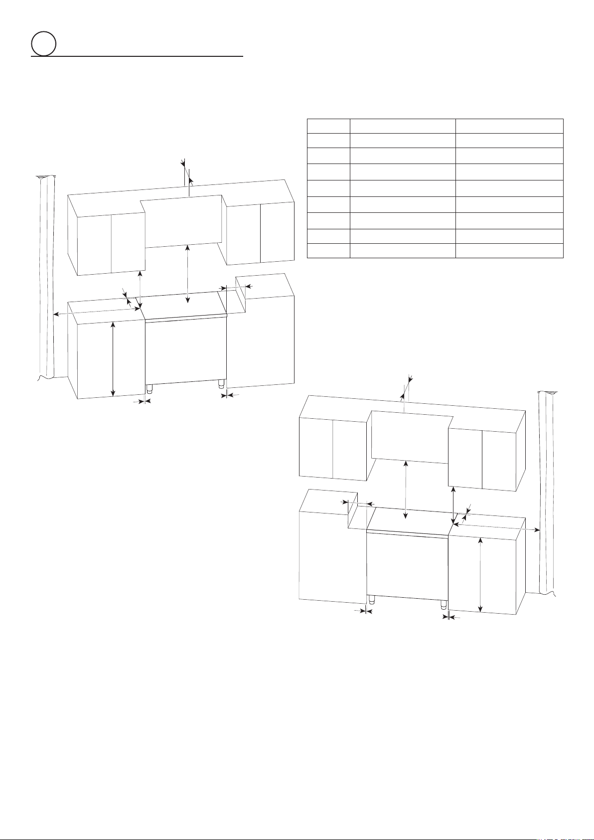
PROXIMITY TO SIDE CABINETS
1. This range may be installed directly adjacent to existing 36”
(914 mm) high base cabinets.
Range dimensions:
• width: 35 7/8” (911 mm) (width of cabinetry opening 36”,
914 mm)
• depth: 25” 1/4 (641 mm)
• height (without backguard): MIN 35” 3/8 (898 mm) - MAX
37” 1/4 (946 mm)
• backguard (height): 3” (76 mm)
• island trim (height): level with cooktop
NOTE: The island trim is supplied with the appliance
while the backguard can be purchased as a separate kit.
Gas line opening: Wall - 1/4” (6 mm) from the right side for
23” 9/16 (599 mm) towards the centre of range; from 8” 1/8
(207 mm) to 10” 1/8 (257 mm) [depending on feet regulation]
from the oor.
Grounded outlet: The grounded outlet should be located
1/4” (6 mm) from the left side for 11” 13/16 (300 mm) towards
the centre of range; from 8” 1/8 (207 mm) to 10” 1/8 (257
mm) [depending on feet regulation] from the oor.
IN CANADA: The electric cord with 4-prong ground plug
(NEMA 14-50P) has a length of 72” (1830 mm).
2. Range may be installed with zero clearance adjacent to
(against) combustible construction at the rear and on the
sides below the cooktop. The range CANNOT be installed
directly adjacent to sidewalls, tall cabinets, tall appliances,
or other side vertical surfaces above 37” 1/2 (953 mm) max
height (depending on the height of the feet adjustment).
There must be a minimum of 11” 13/16 (300 mm) side
clearance from the range to such combustible surfaces TO
THE LEFT and TO THE RIGHT above the 36” (914 mm) high
countertop.
3. The maximum upper cabinet depth recommended is 13”
(330 mm). A ventilation hood or a wall cabinet above the
range must be a minimum of 30” (762 mm) or 36” (914 mm)
(see also “Additional information about minimum clearance
from cooking surface to overhead cabinet or ventilation
hood” here below) above the cooking surface, for a width of
minimum 36” (914 mm): it has to be centered with the range.
Side wall cabinets above the range must be a minimum of
18” (457 mm) above the countertop.
4. Air curtain or other overhead range hoods, which operate
by blowing a downward air ow on to a range, shall not be
used in conjunction with gas ranges other than when the
hood and range have been designed, tested and listed by an
independent test laboratory for use in combination.
Additional information about minimum clearance from
cooking surface to overhead cabinet or ventilation hood:
• 36” (914 mm), overhead cabinet centered above the cooktop
(combustible/unprotected) (see also notes #1, #2, #3)
• 30” (762 mm), overhead cabinet centered above the cooktop
(non-combustible/protected) (see also notes #1, #2, #3)
• 30” (762 mm), ventilation hood centered above the cooking
surface (see also notes #4)
Note #1
To eliminate the risk of burns or re by reaching over heated surface
units, cabinet storage space located above the surface units
should be avoided. If cabinet storage is to be provided, the risk can
be reduced by installing a rangehood that projects horizontally a
minimum of 5 “ (127mm) beyond the bottom of the cabinets.
Note #2
36” (914mm) minimum clearance between the top of the cooking
surface and the bottom of an unprotected wood or metal cabinet;
or 30” (762mm) minimum when bottom of wood or metal cabinet
is protected by not less than 1/4” thick ame retardant millboard
covered with not less than No. 28 MSG sheet steel, 0.015” (0.4
mm) thick stainless steel, 0.024” (0.6 mm) thick aluminum, or
0.020” (0.5 mm) thick copper.
Note #3
Non-combustible surfaces as dened in ‘National Fuel Gas
Code’ (ANSI Z223.1, Current Edition). Clearances from noncombustible materials are not part of the ANSI Z21.1 scope and
are not certied by CSA.
Note #4
Refer to local/national codes for ventilation requirements.
Backguard
Island trim
3” (76 mm)
MIN 35” 3/8 (898 mm)
MAX 37” 1/4 (946 mm)
25” 1/4
(641 mm)
35” 7/8
Fig. 1.1a Fig. 1.1b
66
(911 mm)
MIN 35” 3/8 (898 mm)
MAX 37” 1/4 (946 mm)
25” 1/4
(641 mm)
35” 7/8
(911 mm)

GAS AND ELECTRIC CONNECTION
1
Dotted line showing the position
of the range when installed
A
Area for
ELECTRICAL
connection
C
D
Area for
GAS connection
Ref. inch mm
A 1/4” 6
B 23” 9/16 599
A
B
C 8” 1/8 - 10” 1/8 (*) 207 - 257 (*)
D 11” 13/16 300
(*) : Depending on feet regulation
ISLAND TRIM AND BACKGUARD
• It is mandatory to install and use the appliance
with either the island trim or the optional 3”
backguard correctly in place.
• The island trim is already tted to the appliance
while the 3” backguard can be purchased as a
separate kit.
• If replacing the island trim with the 3” backguard,
assemble it by using the same screws/spacers
used for xing the island trim (gs. 1.3a, 1.3b).
Fig. 1.3a
Fig. 1.2
A
A
ISLAND TRIM
B
BACKGUARD
Fig. 1.3b
B
77
1
Fig. 1.4a
G
PROXIMITY TO SIDE CABINETS
Ref. inch mm
A 0” 0
F
D
E
C
H
B 37” 1/2 (*) 953 (*)
C 11” 13/16 300
D 30” or 36” minimum (**) 762 or 914 minimum (**)
E 18” minimum 457 minimum
F 13” maximum 330 maximum
G 20” minimum 500 minimum
H 0” 0
(*) Maximum height of cabinetry immediately adjacent to the
range (from oor to countertop).
Depending on the height of the feet adjustment.
The cooking surface must sit ush or above countertop level.
(**) See also “Additional information about minimum clearance
from cooking surface to overhead cabinet or ventilation
hood” at page no.6.
B
F
A
A
Fig. 1.4b
D
C
E
H
G
B
A
A
88
1
0 mm
0"
+ 1" 31/32
+ 50 mm
Fig. 1.7
Fig. 1.5
Fig. 1.6
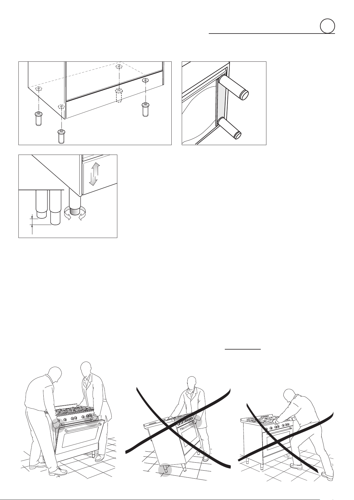
FITTING THE ADJUSTABLE FEET
The adjustable feet must be fitted to the base of the cooker before use.
Rest the rear of the cooker on a piece of the polystyrene packaging exposing the base
for the fitting of the feet.
ATTENTION: Most important! Pay special attention not to damage the range during
this operation.
Fit the 4 legs by screwing them tight into the support base as shown in picture 1.5 - 1.6.
LEVELLING THE COOKER
The cooker may be levelled by screwing the lower ends of the feet IN or OUT (fig. 1.7).
It is important to observe the directions of figure 1.7.
MOVING THE COOKER
WARNING
When raising cooker to upright position always ensure two people carry out this
manoeuvre to prevent damage to the adjustable feet (fig. 1.8a).
WARNING
Be careful: do not lift the cooker by the door handle when raising to the upright position
(fig. 1.8b).
WARNING
When moving cooker to its final position
Lift feet clear of floor (fig. 1.8a).
Fig. 1.8a Fig. 1.8b
DO NOT DRAG
Fig. 1.8c
(fig. 1.8c).
99
 Loading...