

Page 1
Spectro Pro
User’s Manual
Version 1.0
COPYRIGHT © 2001
Tufts University and Vernier Software & Technology
ISBN: 1-929075-15-4
07/15/01
Distributed by
Vernier Software & Technology
13979 SW Millikan Way
Beaverton, Oregon 97005-2886
(503) 277-2299
FAX (503) 277-2440
www.vernier.com
Page 2

2 Spectro Pro
Page 3

Spectro Pro
Short Table of Contents
SPECTRO PRO OVERVIEW ................................................................................................................................9
RO
PECTRO
S
HOW TO.................................................................................................................................................................15
P
UICK START
Q
..................................................................................................................................11
HANGE GRAPH APPEARANCE
C
ONFIGURE DATA COLLECTION OPTIONS
C
IEW OTHER WINDOW TYPES
V
NALYZE DATA
A
ERFORM DATA TABLE FUNCTIONS
P
AVE AND PRINT DATA
S
....................................................................................................................................................20
..............................................................................................................................15
..............................................................................................................17
...............................................................................................................................19
......................................................................................................................23
.........................................................................................................................................27
TEACHER’S GUIDE.............................................................................................................................................29
OFTWARE INSTALLATION
S
DEAS FOR USING SPECTRO
I
.....................................................................................................................................29
RO
IN THE CLASSROOM
P
..............................................................................................31
SPECTRO PRO REFERENCE.............................................................................................................................33
EYSTROKE EQUIVALENTS
K
OOLBAR
T
URSOR CONTROLS
C
PECTRO
S
..............................................................................................................................................................33
...............................................................................................................................................34
RO
ENUS
P
M
...................................................................................................................................33
............................................................................................................................................36
APPENDIX A TROUBLESHOOTING GUIDE................................................................................................61
APPENDIX B USING SPECTRO PRO ON A NETWORK............................................................................. 65
APPENDIX C INTERFACES COMPATIBLE WITH SPECTRO PRO........................................................67
APPENDIX D VERNIER SENSORS..................................................................................................................69
ENSOR PRICE LIST
S
...............................................................................................................................................70
Spectro Pro 3
Page 4

4 Spectro Pro
Page 5

Spectro Pro
Full Table of Contents
SPECTRO PRO OVERVIEW ................................................................................................................................9
Overview............................................................................................................................................................ 9
RO
PECTRO
S
Purpose............................................................................................................................................................ 11
Install software................................................................................................................................................ 11
Attach spectrophotometer ...............................................................................................................................11
USB connection...............................................................................................................................................12
Start up spectro Pro ........................................................................................................................................12
Collect data .....................................................................................................................................................13
Adjust graph ....................................................................................................................................................13
If you need more.............................................................................................................................................. 13
HOW TO.................................................................................................................................................................15
P
UICK START
Q
..................................................................................................................................11
HANGE GRAPH APPEARANCE
C
..............................................................................................................................15
Change axis limits manually ...........................................................................................................................15
Change axis limits automatically .................................................................................................................... 15
Zoom in on a graph ......................................................................................................................................... 15
Scroll to a new portion of graph without rescaling.........................................................................................16
Change what is plotted.................................................................................................................................... 16
Change other graph options............................................................................................................................16
ATA COLLECTION OPTIONS
D
.................................................................................................................................17
Set sampling speed (data collection rate) ...................................................................................................... 18
Set experiment length ...................................................................................................................................... 18
Sort data .......................................................................................................................................................... 18
IEW OTHER WINDOW TYPES
V
...............................................................................................................................19
Graph...............................................................................................................................................................19
Table................................................................................................................................................................19
Text..................................................................................................................................................................19
Meter ...............................................................................................................................................................19
NALYZE DATA
A
....................................................................................................................................................20
Read values from cursor..................................................................................................................................20
Read delta values between two points.............................................................................................................20
Read values from graph ..................................................................................................................................20
Display tangent lines....................................................................................................................................... 20
Compare runs.................................................................................................................................................. 20
Fit a line to data (linear regression)...............................................................................................................20
Interpolate between points .............................................................................................................................. 20
Fit functions to data ........................................................................................................................................21
Manual Fit (Model Data)................................................................................................................................ 21
Change Displayed Precision of Fit Parameters..............................................................................................22
ERFORM DATA TABLE FUNCTIONS
P
......................................................................................................................23
Change what runs appear in the data table....................................................................................................23
Change a column’s name, color, width, or digits displayed........................................................................... 24
Calculate new values from raw data (new columns).......................................................................................24
Enter data manually........................................................................................................................................26
Copy data to a spreadsheet or graphing program..........................................................................................26
AVE AND PRINT DATA
S
.........................................................................................................................................27
Save data, calibration and configuration........................................................................................................27
Paste data into other applications ..................................................................................................................27
5 Spectro Pro
Page 6

Retrieve an experiment.................................................................................................................................... 27
Print a graph or data table .............................................................................................................................27
Print the screen ............................................................................................................................................... 27
Set default file locations..................................................................................................................................27
TEACHER’S GUIDE ............................................................................................................................................29
OFTWARE INSTALLATION
S
.....................................................................................................................................29
Required materials..........................................................................................................................................29
Initial setup......................................................................................................................................................29
Software installation Macintosh ..................................................................................................................... 30
Software installation Windows........................................................................................................................ 30
Software installation (network).......................................................................................................................30
RO
DEAS FOR USING SPECTRO
I
IN THE CLASSROOM
P
..............................................................................................31
Experiment files are important!...................................................................................................................... 31
Experiment files included with Spectro Pro....................................................................................................31
Protecting experiment files ............................................................................................................................. 31
Creating an experiment file.............................................................................................................................32
Customizing Spectro Pro................................................................................................................................. 32
Using Spectro Pro on a network..................................................................................................................... 32
Using Spectro Pro on stand-alone computers ...............................................................................................32
SPECTRO PRO REFERENCE ............................................................................................................................ 33
EYSTROKE EQUIVALENTS
K
OOLBAR
T
URSOR CONTROLS
C
..............................................................................................................................................................33
...............................................................................................................................................34
...................................................................................................................................33
Graph Window.................................................................................................................................................34
Graph title.......................................................................................................................................................34
Tick mark labels.............................................................................................................................................. 34
Axis labels ....................................................................................................................................................... 34
Scroll arrows................................................................................................................................................... 34
Axes .................................................................................................................................................................34
Graph options.................................................................................................................................................. 35
Selecting a graph............................................................................................................................................. 35
Table Window.................................................................................................................................................. 35
Select All/None................................................................................................................................................ 35
Column properties...........................................................................................................................................35
Column options ............................................................................................................................................... 35
Column order .................................................................................................................................................. 35
Edit cell contents............................................................................................................................................. 35
Strikethrough Rows......................................................................................................................................... 35
RO
PECTRO
S
ENUS
P
M
...........................................................................................................................................36
Apple menu...................................................................................................................................................... 36
File menu.........................................................................................................................................................36
Edit menu......................................................................................................................................................... 40
Experiment menu.............................................................................................................................................41
Data menu ....................................................................................................................................................... 43
Analyze menu................................................................................................................................................... 47
View menu........................................................................................................................................................51
Setup menu ......................................................................................................................................................57
Window menu.................................................................................................................................................. 58
Help menu........................................................................................................................................................59
APPENDIX A TROUBLESHOOTING GUIDE................................................................................................ 61
6 Spectro Pro
Page 7

APPENDIX B USING SPECTRO PRO ON A NETWORK............................................................................. 65
General principles...........................................................................................................................................65
Spectro Pro preferences.................................................................................................................................. 65
Macintosh........................................................................................................................................................65
Windows...........................................................................................................................................................66
Student use of Spectro Pro on a network.........................................................................................................66
APPENDIX C INTERFACES COMPATIBLE WITH SPECTRO PRO........................................................67
Which Interface? .............................................................................................................................................67
APPENDIX D SENSORS FOR USE WITH SPECTRO PRO..........................................................................69
Sensors supported by all interfaces.................................................................................................................69
Additional sensors for the ULI and LabPro....................................................................................................69
Sensor for LabPro only ................................................................................................................................... 69
Experiment and calibration files.....................................................................................................................69
ENSOR PRICE LIST
S
...............................................................................................................................................70
Spectro Pro 7
Page 8

Spectro Pro Overview
Overview
The Spectro Pro user’s guide is divided into four main sections: This
Overview, a How To section, a Teacher’s Guide, and the Spectro Pro
Reference. This Overview concludes with a “Quick Referen ce” Section
for the eager. In s tru ctors us in g Spectro Pro in the classroom will want to
read the Teach er’s Guide for helpful tips. The How To section explains
common operations with Spectro Pro. You can read it in any order. The
Reference Section explains the function of all the menu items and how
to use them. On-line help is available: Choose Help from the Apple
menu (Macintosh) o r the Help menu (Windows).
Initial software installation and the connection of the interface are
explained in the Teacher’s Guide. Refer to the troubleshooting chart in
Appendix A if you have problems. Detailed information for network us e
can be found in Appendix B. Appendix C reviews the interfaces that can
be used with Spectro Pro, and how to choose among them. A list of
spectrophotometers compatible with Spectro Pro is in Appendix D.
Some familiarity with the use of Macintosh or Windows computers and
application software is assumed in this manual.
Spectro Pro has been designed by Gretchen Stahmer DeMoss, Dan
Holmquist, Jessica Fink, and Diana Gordon of Vernier Software &
Technology, and by Stephen Beardslee and Mary Dygert at the Center
for Science and Mathematics Teaching at Tufts University. The d esign
was implemented by Stephen Beardslee, Mary Dygert and Gretchen
Stahmer DeMoss.
Spectro Pro is copyrighted by Vernier Software & Technology and Tufts
University. You are permitted to make as many copies as you wish of the
Spectro Pro software and the User's for use in your own high school,
middle school, or college department. You may use Spectro Pro on
networks within your school or department at no extra cost. Our site
license also permits your students to load a copy of Spectro Pro on their
home co mputers.
The Spectro Pro manual is copyright ©2001 by Vernier Software &
Technology. John Gastineau wrote this manual, with revisions by Diana
Gordon. Macintosh is a registered trademark of Apple Computer, Inc.
Microsoft, Windows, Windows NT, and Win32s are either registered
trademarks or trademarks of Microsoft, Inc.
Spectro Pro 8
Page 9

10 Spectr o Pro
Page 10

Spectro Pro Quick Start
Purpose
Install software
Attach spectrophotometer
This section is provided for those who do not read software manuals. It
outlines the essential steps to get started with Spectro Pro.
To install Spectro
•
Place the Spectro Pro CD in the CD-ROM drive of your computer.
•
Double-click the icon Install Spectro Pro and follow the instructions
on screen.
To install Spectro
95/98/2000/NT 4.0, follow the s e steps
•
Place the Spectro Pro CD in the CD-ROM drive of your computer.
•
If you have Autorun enabled, the installation will launch automatically;
otherwise choose Settings Æ Control Panel from the Start menu.
Double click on Add/Remove Programs. Click on the Install b utton in
the resulting dialog box.
•
The Spectro Pro installer will launch, and a series of dialog boxes will
step you through the installation of the Spectro Pro software. You will
be given the opportunity to either accept the default directory or enter a
different directory.
•
If using a Sp ec 20D or D+ (digital signal):
You may connect directly to a computer Serial Port using an SP CIBM cable for PC or an SPC-MAC cable for Mac. If a serial port is
not available, connect through an interface as directed below (See
“If using a Spec 20 or 20+”), or use a Key Span serial-to-USB
adapter.
Pro
on a Power Macintosh, follow these steps
Pro
on a computer running Windows
:
:
•
If using a 20 Genesys (digital signal only):
You may connect directly to a computer Serial Port using a GEN-PC
cable for PC or a GEN-MAC cable for Mac.
•
If using a Flinn spectrophotomete r (digital signal only):
You may connect directly to a computer Serial Port using an SP CFL I cable for PC or SPC-FLM cable for Mac.
•
If using a Sp ec 20 or 20+ (analog signal only):
You must connect to a computer interface:
¾ LabPro: Connect to CH1 of a Vernier LabPro with an SPC-BTA
cable.
¾ ULI: Connect to DIN1 of a ULI using an SPC-DIN cable.
¾ Serial Box Interface: Connect to Port 1 of a Serial Box Interface
using an SPC-DIN cable.
¾ Attach the power adapter to the interface and to a source of
115VAC.
¾ Connect the interface to the computer using the supplied cable.
On the Macintosh you can use any serial port, including the
modem and printer ports. On the PC you can use any of the
COM1, 2, 3 or 4 serial ports. LabPro users can also use the USB
port and cable on a USB-equipped PC or Macintosh.
Spectro Pro 8
Page 11
USB Connection
Tur n on spectrophotometer
Start up Spectro
Pro
If you have a USB-only comput er, you may c onsider using one of the
following options:
1. For Macintosh computers, attach a Keyspan USB Twin Serial
Adapter*, Part #USA-28x (for information, see www.keyspan.com).
Use Printer Port port selection.
Note:
2. For PC computers, attach a Keyspan High Speed USB Adapter*,
Part #USA-19W (for information, see www.keyspan.com).
Note
:
Use COM 3 por t selection.
3. If y o u have an analog Spec 20 or Spec 20+ (or a Spec 20D or D+,
which have analog as well as digital capability), yo u can connect to
Channel 1 or a LabPro Interface using the SPC-BTA cable.
Note
:
The LabPro interface itself can connect to the USB port of a
Macintosh or PC computer and use Spectro Pro software.
Fol lowing the manufacturer’s dir ections, turn on y our
spectrophotometer.
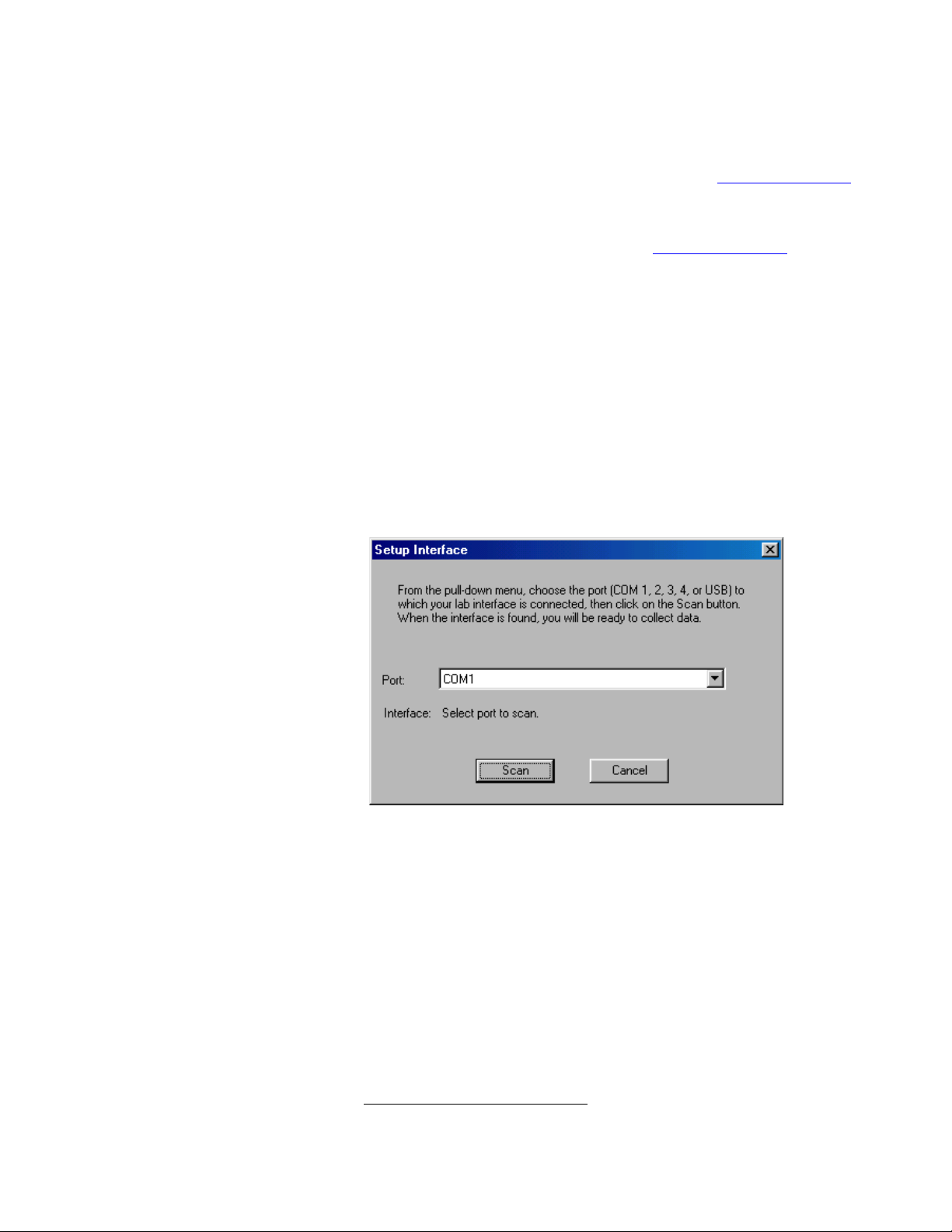
Locate the Spectro Pro icon and double-click on it, or use the Start menu
(Windows 95/98/NT/ME). If the most recently used spectrophotometer
or interface is not detected, the Setup Interface Box will appear on your
screen.
Select the port to which your spectrophotometer or interface is
connected, and click on the Scan button. An icon representing your
interface or spectrophotometer will appear in the toolbar. (Note: your
spectrophotometer must be turned on for this to be successful.) When
this has occurred, click on the OK button in the Setup Interface box. You
will see the following screen on your monitor.
∗
∗
The Keyspan Adapters have not been extensively tested with Spect ro Pro, nor have
other brands of USB to S er ial adapters been examined.
12 Spectr o Pro
Page 12
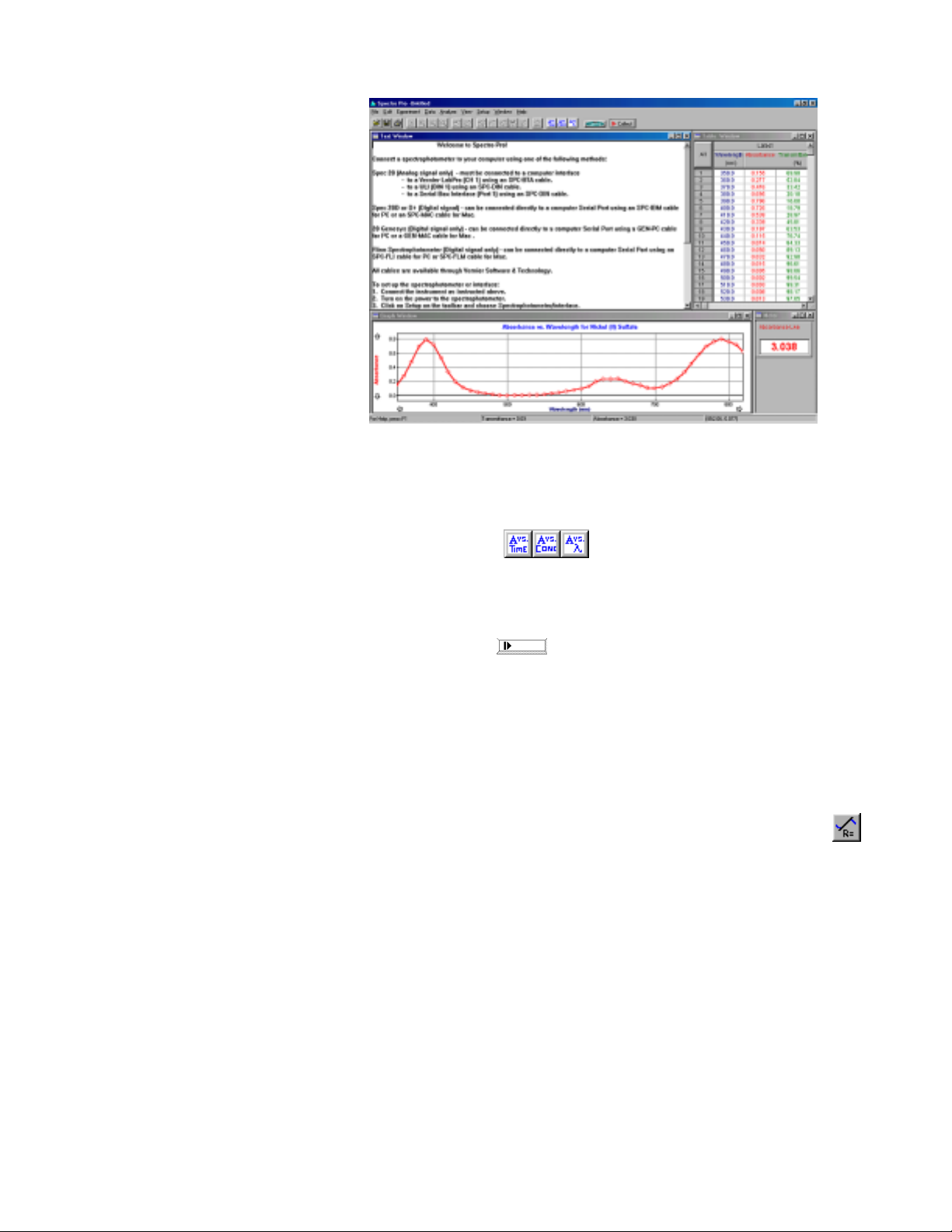
Select Desired Experimental
Setup
•
From the mode buttons in the toolbar select one of the following
experiment files: Absorbance vs. Time, Absorbance vs.
Concentration, or Absorbance vs. Wavelength.
•
Follow the on-screen instructions.
•
Spectro Pro is now ready to collect data.
Collect data
Adjust graph
Insert linear regression line
If you need more
•
Click on the
Collect
button on the toolbar. Follow calibration
instructions, as required, and begin data collection. Spectro Pro will
plot data in the graph window. When you have completed data
collection, click on the Stop button. (In the Absorbance vs. Time
mode data collection will stop automatically at the end of the
designated time.)
•
You can adjust most features of the graph by double clicking the
graph and making changes in the resulting dialog box.
•
First, select a portion of the graphed data by dragging across
it.
•
Then click on the linear fit button on the toolbar.
If you need more information about using Spectro Pro, check the on-line
help files.
Spectro Pro 8
Page 13
Change axis limits manually
How To
How To
In the How To section you will learn to perform specific functions in
Spectro Pro. The tasks are organized in six broad categories: graph
appearance, data collection options, non-graph windows, data analysis,
data tables , and saving a nd printing data.
If you have further questions, go to the reference section and read the
descriptions of the relevant menu items, or check the index for other
references.
Change Graph Appearance
There are many ways that you might want to change the appearance of
the initial graph. The range of the x or y axis might not be ideal. Or, you
might want to plot other quantities on each axis. You can change most
elements of the graph directly by clicking on them, so if you are not s u re
how to change a given item, begin by clicking on it and see what
happens. Here are some things you can quickly change on a graph.
Often you will measure some quantity and the plotted line will only fill a
portion of the screen. You can quickly change the range of values plotted
by clicking the numbers at the ends of the graph axes. Type a new value
and press enter.
Change axis limits
automatically
Zoom in on a graph
To make the plotted data fill the graph window for this particular
collection of data, click the Autoscale Once button on the toolbar.
To turn automatic scaling on for all subsequent collections of data
choose V iew Æ Set Axes to Autoscale.
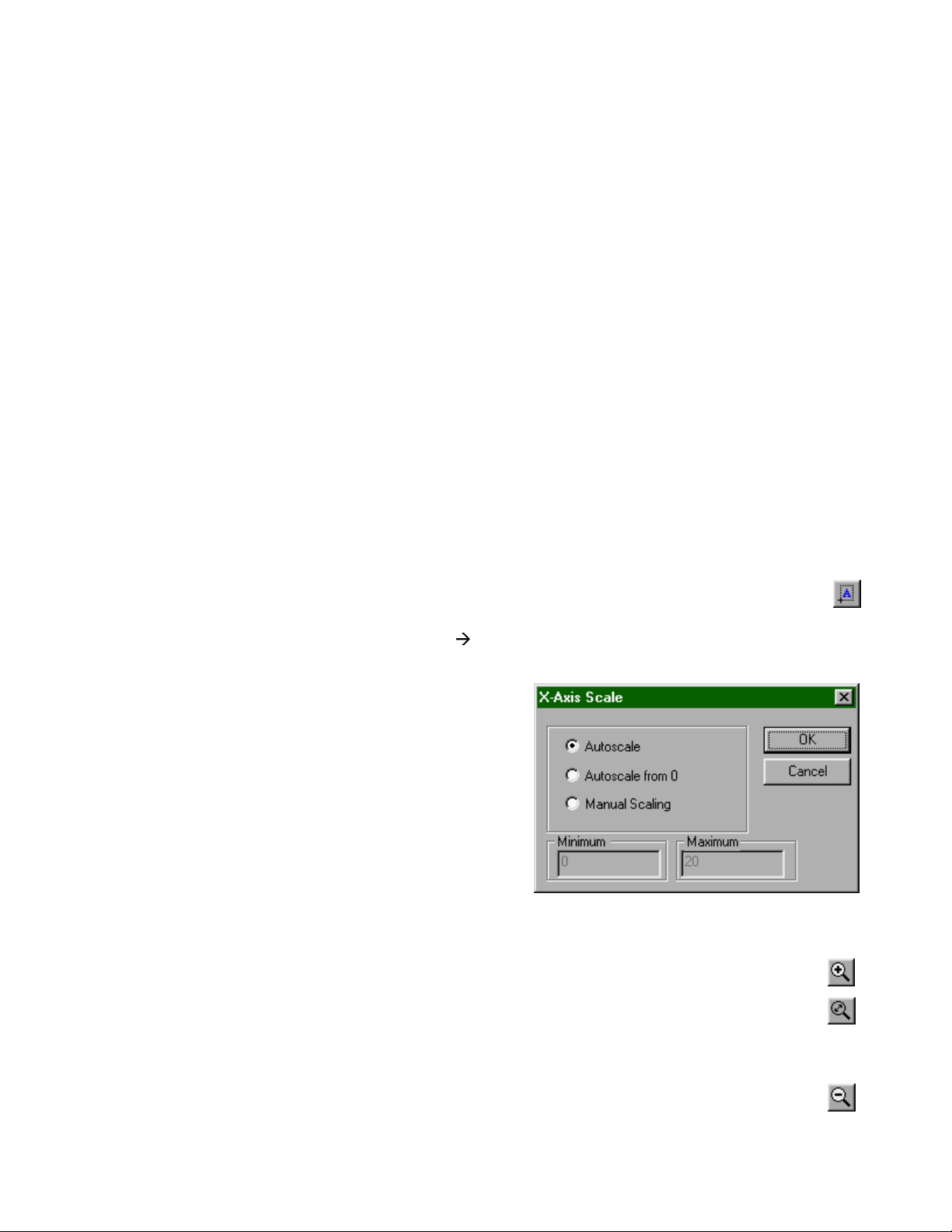
To change just the x- or just the y-axis limits, click on the desired axis.
You will see a dialog
box:
Choose the type of
scaling you want.
Autoscale Once will
set the axis limits so
the data just fill the
axis. The origin may
not necessarily be
included unless you
choose Autoscale
from 0, in which case
the origin is always included. Manual scaling allows you to enter the
minimum and maximum limits manually. The choice made here will
determine how Spectro Pro scales a new graph.
To enlarge a portion of a graph to fill the screen, drag across the
desired area with the mouse, leaving a rectangle on the graph
enclosing the area of interest. Then click on th e Zoom In button
on the toolbar. If you don’t like what you see, you can reverse the
action by clicking the Undo Zoom button.
The Zoom Out button will double the range of both the x and y
axes. It does not undo a Zo om In—Undo Zoom does that.
Spectro Pro 8
Page 14
How To
Scroll to a new portion of
graph without rescaling
Change what is plotted
Change other graph options
Sometimes the plotted data will extend off the screen. The arrows at the
ends of the vertical and horizontal axes can be u sed to scroll across the
data. Using the scroll arrows is equivalent to changing both extremes of
the axis limits at the same time while maintaining the same interval
between extremes.
The default plot will usually be the sensor output as a function of time or
a prompted input. You may want to plot some other quantities. Click
either on the x- or y-axis label to get a check box list of all the possible
quantities for plotting. Some combinations will not be useful. If you
don’t see what you want to plot, you may b e ab le to create a new column
of data based on the raw data. See create new columns below. Once
you’ve define d a new column you can plot it.
If you double-click on a graph, you will get a dialog box that allows you
to change a number of graph options. Brief descriptions follow; for
additional information see Spectro Pro reference.
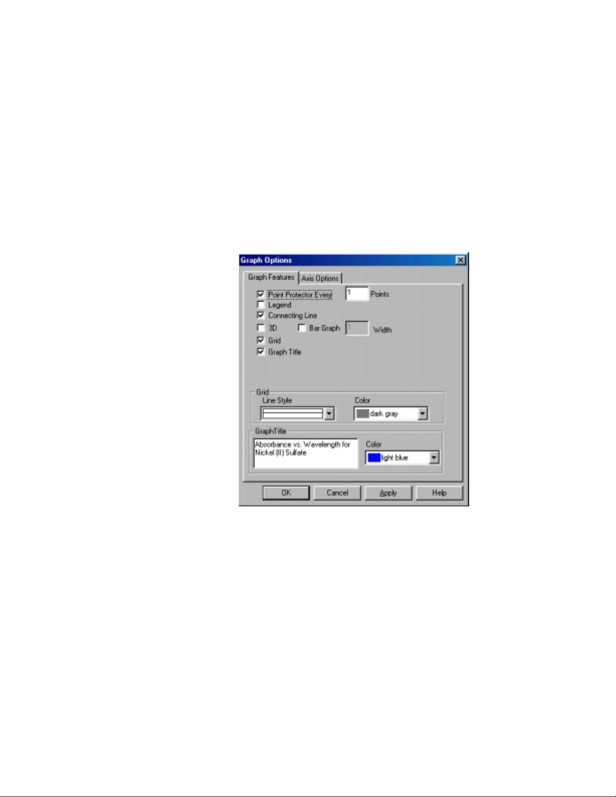
The following functions are found on the Graph Options dialog. Double
click a graph to open this dialog box.
Select point protectors as desired. A point protector outlines a data point.
See data points directl y (poi nt
protectors)
You may want to outline every 5th or 10th point to keep the graph from
getting crowded.
Adding a legend opens a floating box holding a key to the plotted data.
Add/remove a legend
Connect data points
Select the Connecting Line option to connect data points with lines.
Without this option selected individual data points are visible.
Select or deselect the grid as desired. You can als o adjust the line style
Add/remove the grid
and color of the gridlines in this dialog box.
Select or deselect the Graph Title option as desired. Spectro Pro
Graph title
attempts to create a title for a graph based on the axis labels, but you can
override the automatic title by entering text in the Graph Title f ield.
16 Spectr o Pro
Page 15
How To
Data Collection Options
The best way to set up Spectro Pro for a particular experiment is to open
an experiment file. Spectro Pro comes with experiment files that load
appropriate data collection parameters and prepare Spectro Pro to
receive data. Even if you want to use your own custom configuration,
these files are good starting points.
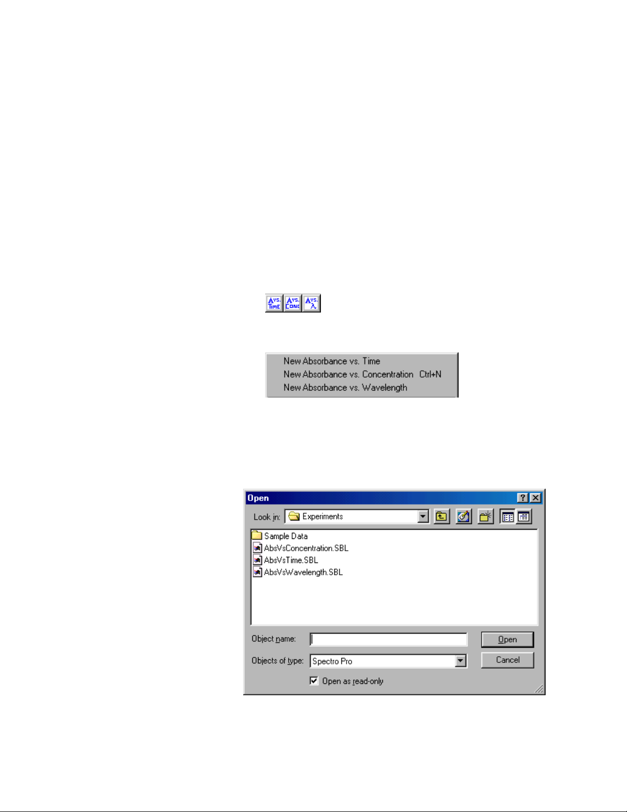
Spectro Pro offers three data collection options:
•
Absorbance vs. Time
•
Absorbance vs. Concentration
•
Absorbance vs. Wavelength
You may select a data collection option in one of three ways:
(1) Click on the appropriate icon in the toolbar;
(2) Choose the appropriate mode from the File menu.
Or (3) choose Open from the File menu. You will see files for the three
possible modes of data collection (Absorbance vs. Time, Absorbance vs.
Concentration, and Absorbance vs. Wavelength). An additional folder
holds sample data files. (You can also save special experiment files you
create in this location.) Select the file of your choice.
Spectro Pro is now ready t o acquire data.
Spectro Pro 8
Page 16
How To
Set sampling speed
(data collection rate)
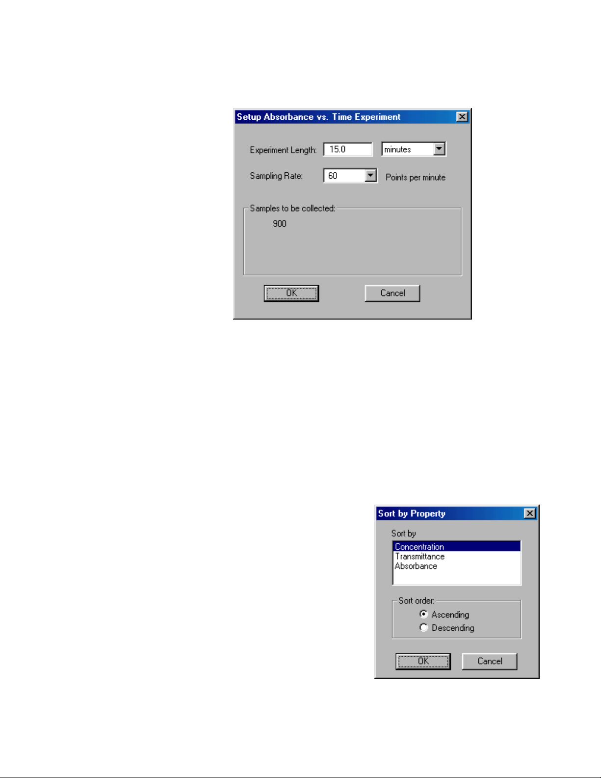
In the Absorbance vs. Time mode, Experiment Length and Sampling
Rate can be selected. Click Setup on the toolbar, and select “Setup
Absorbance vs. Time” to access this feature.
In the Data Collection Sampling tab set the time units you want and the
sampling rate, i.e., the number of points collected each second (select
from 2, 1, .5, or .1 samples/second), minute (select from 60, 30, 6, 1, .25
samples/minute), or hour (select from 3600, 1800, 360, 60, 25
samples/hour). Sampling speed is a trade-off; too fast a speed yields
unwieldy data sets, while too slow a collection rate will miss important
experimental details. The maximum sampling speed depends on the
interface used and the number of input channels. Spectro Pro can collect
at most 30,000 points in one input channel.
Set the total time of data collection for Real Time Collect, Repeat and
Set experiment length
Selected Events modes in the Data Collection Sampling tab. You can
also set the experiment length by changing the maximum time axis label
to the desired value.
If the column used for the
Sort data
horizontal axis is not in
ascending or descending order
the graph will not be drawn
correctly when connecting
lines are enabled. This can
easily happen when the column
consists of prompted entries.
Choose Sort Data from the
Data menu, choose the column
by which to sort, click
ascending or descending as
desired, and click OK.
18 Spectr o Pro
Page 17
How To
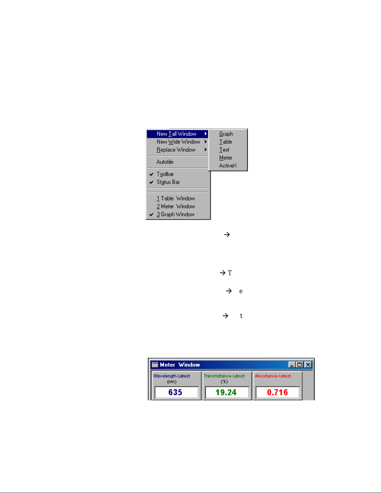
View Other Window Types
The Windows menu contains commands that add or replace windows on
the Spectro Pro screen. Since each new window reduces the screen area
available for the existing windows, the precise action of the window
commands depends on the currently active window. New Tall Window
halves the width of the current window and creates a new window of
vertical orientation of the selected type. Similarly, New Window Wide
halves the height of the current window and creates a wide window of
the selected type. Replace Window replaces the selected window with a
window of the newly selected type.
Graph
Table
Text
Meter
Choose New Tall Window Æ Graph from the Window menu. A new
graph window will be created. Note that it may be more useful to create
a new pane in a graph window instead since less screen area is required .
See Graph Layout in the View menu of Spectro Pro Reference for more
information.
Choose New Tall Window Æ Table from the Window menu. A new data
table window will be created.
Choose New Tall Window Æ Text from the Window menu. A new
window will be created for text entry. You can use this window for
laboratory instructions, information about the experiment, or other notes.
Choose New Tall Window Æ Meter from the Window menu. A dialog
box will open which allows you to select the data columns to be
displayed in a digital meter window. Then a new window will be created
containing the selected digital readouts. Double-click on the meter
window to change which quantities are displayed.
Spectro Pro 8
Page 18
How To
Analyze Data
Read values from cursor
Read delta values between
two points
Read values from graph
Display tangent lines
Compare runs
As you move the mouse cursor around the graph the coordinates of the
point directly under the cursor point appear in the rightmost area of the
status bar at the bottom of the main Spectro Pro window.
You may click, hold, and drag the mouse cursor from one point to
another on the graph to get the delta between two points. The horizontal
and vertical distance (∆x and ∆y) between the two points is displayed
next to the mouse cursor position in the rightmost area of the status bar
at the bottom of the main Spectro Pro window.
Choose Examine from the Analyze menu.
A floating box will appear, accompanied by the numerical value at the
mouse pointer position. As the mouse cursor is moved across the graph,
the readout will change and the data table will scroll to highlight the
associated numerical values.
To draw tangent lines and read the slope of those lines, choose
Tangent from the Analyze menu (or click on the tangent line
button on the toolbar) and move the pointer to the place where you want
the slope. A floating box will appear, containing the numerical value of
the data and the slope of the tangent line at the pointer position. The
number of points used in calculating the tangent may be set by choosing
Options fr om the Experiment menu.
Often you will want to compare two similar r uns of collected data. When
you get the first useful run, choose Store Latest Run from the Data
menu. Now you may take additional data and the stored run will not be
lost. The data will be retained through subseq uent data collections, and
can be displayed or hidden as desired. Stored runs are numbered
sequentially. Any number of runs can be stored, and will be saved wh en
yo u save an experiment to di sk.
The Data menu has four more relevant functions. Hide Run will
temporarily remove the selected run from the graph, Show Run will put
it back, Rename Run allows changing the displayed name of a selected
stored run, and About Run shows the timestamp of the d ata and allows
you to enter notes about the run. Using the Hide/Show functions you can
superimpose any desired set of runs.
Fit a line to data
(linear regression)
Interpolate between points
Fit functions to data
20 Spectr o Pro
To fit a straight line to your data, select the d esired portion of the
data by dragging across it. Next, choose Linear Fit from the
Analyze menu (or click on the linear regression button on the toolbar). A
straight line will be fit to the indicated data, and the slope and in tercept
information will be displayed in a floating box. Displayed precision can
be adjusted by double-clicking on the floating box to open a new dialog
box.
To interpolate between data points on a line, click on the
Interpolate button on the toolbar. To interpolate between data
points on a curve, first fit a function to a range of data. choose
Interpolate from the Analyze menu. The floating box for the curve fit
will expand to show the coordinates of points along the fitted curve.
Move the mouse pointer to the place you want to interpolate.
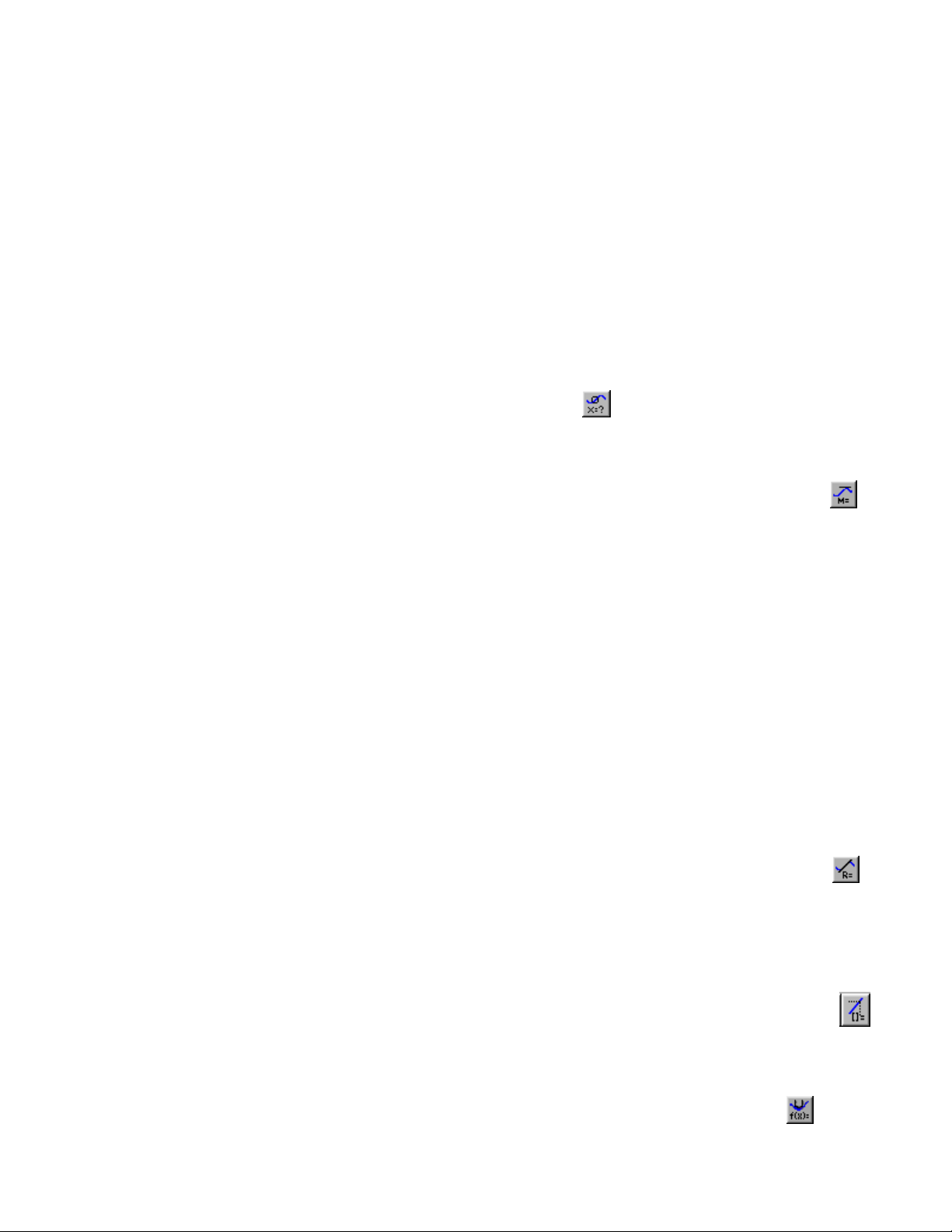
To fit more complex functions to your data choose Automatic
Page 19
How To
Curve Fit from the Analyze menu (or click on the Automatic Curve Fit
button on the toolbar). You will see the following dialog box. To fit to
just a part of your data, you must first select the desired portion of the
data by dragging across it.
Manual Fit
(Model Data)
Now choose a mathematical relation from the list at the lower left. You
may need to scroll through the list to find the appropriate function. The
polynomial choice also requires that you set the degree of the
polynomial. Next, choose the data set you want to use from the Perform
Fit On menu. Click on Try Fit to see the result. If you like, choose
another function or data column for another trial fit. You can also select
a different ran ge of data by dragging acros s the graph regi on. Click on
Try Fit to see the new fit. Once you have a fit that you like, click on OK
to display the fitted curve on your graph. Click on Cancel to discard all
fits. The Save button will place the fitted curve on the main graph
window without closing the dialog box.
If you want a linear regression line to be forced through the origin, select
Automatic Curve Fit, from the Analyze menu and then select
Proportional. The Proportional fit (y=Ax) has a y-intercept value equal
to 0; therefore, this regression line will always pass through the origin of
the graph.
To superimpose a function over your data, make a graph active by
clicking on it once. Select Manual Curve Fit from the Analyze menu. In
the dialog box select a function. Adjust parameters as needed to fit the
function t o your data.
Note that poorly chosen parameters may make the function miss the
graphed region entirely. In this case it is difficult to adjust the parameters
by trial and error. You may want to select parameters carefully so that the
function matches the data at the y-intercept, and adjust values from
there.
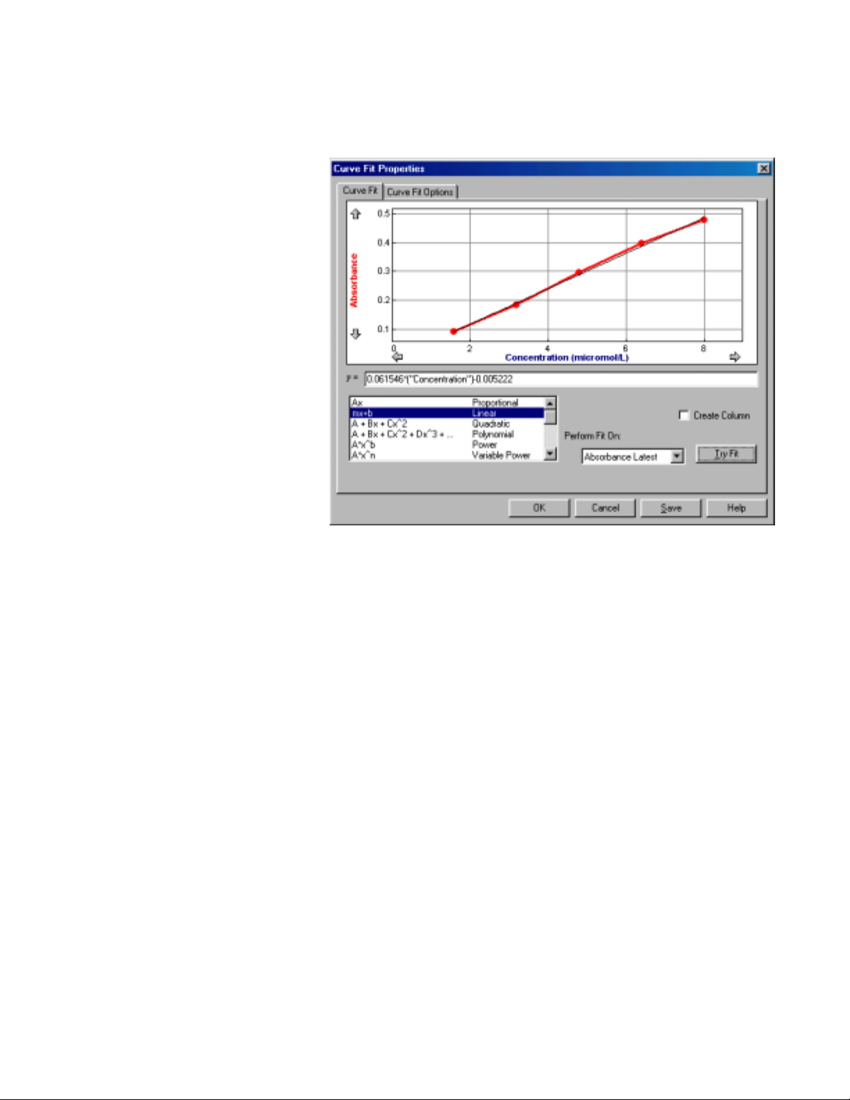
Change Displayed Precision
of Fit Parameters
You can adjust eith er the number of significant digits or the number of
decimal places used in displaying fit statistics and parameters. After you
have completed a fit, double-click on the floating box containing the fit
Spectro Pro 8
Page 20
How To
information. A floating box options dialog will open, allowing you to set
the line color, line style, fit co efficients displayed, and their precision.
22 Spectr o Pro
Page 21
Perform Data Table Functions
How To
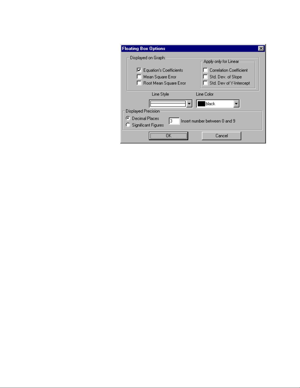
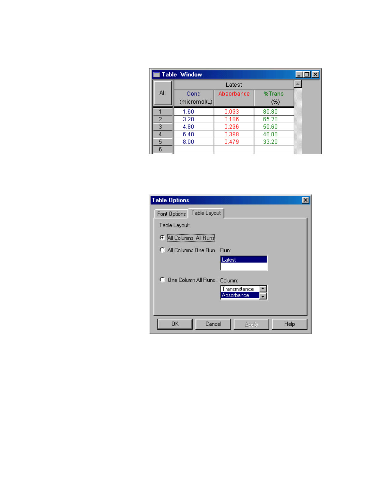
Change what runs appear in
the data table
You can control what is displayed in the Data Table Window. Double
click on the data table to change table options and click on the Table
Layout tab. You will see this tabbed dialog box.
Choose the table layout you need. The choices allow you to display all
columns from all runs, just a single run, or just one column from all
runs. You can further control what is shown in the data table by hiding
individual columns in the Column Options dialog found in the Data
menu, or by do uble-clicking a column header.
The Font Options tab shows a dialog in which you can choose display
font and size for the da t a table.
Spectro Pro 8
Page 22
How To
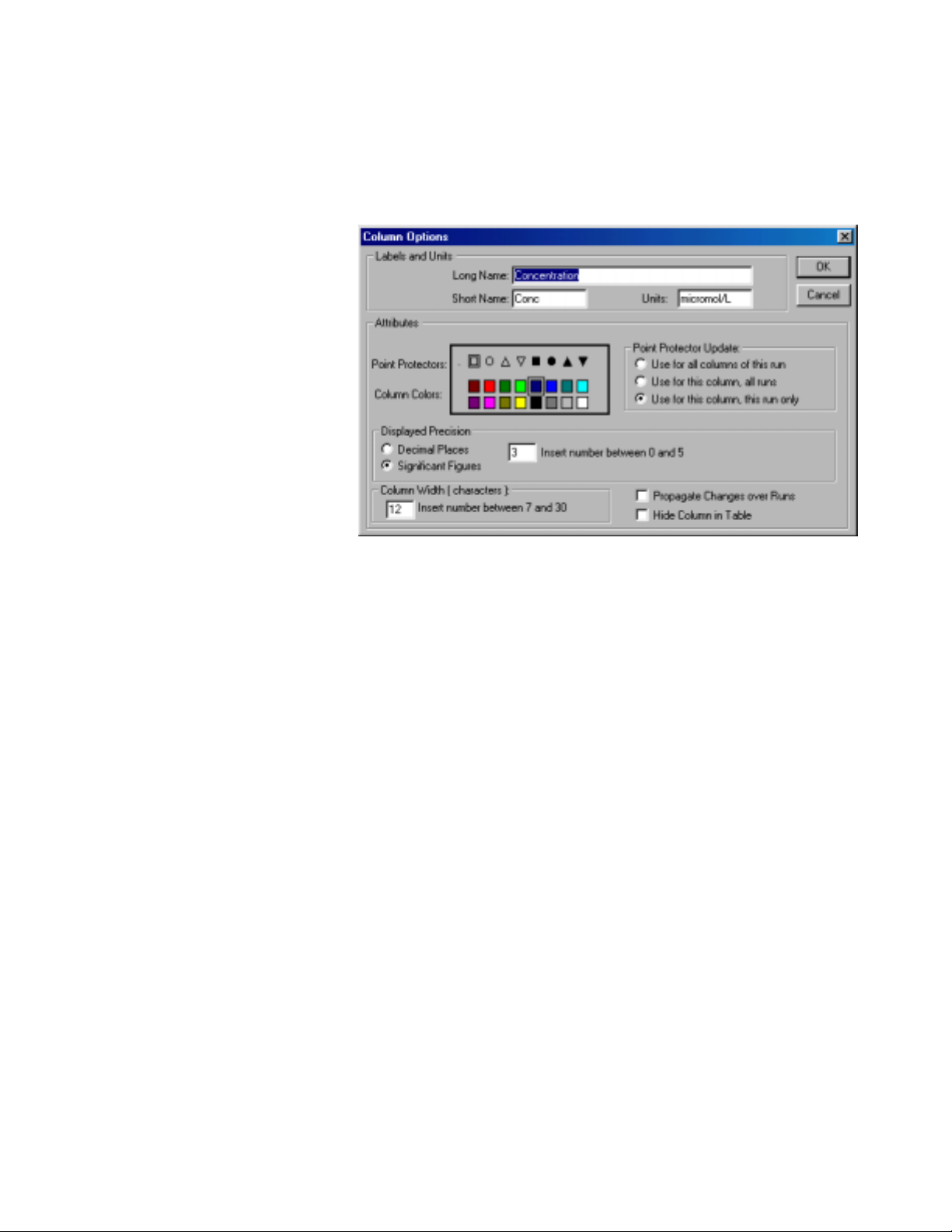
Change a column’s name,
color, width, or digits
displayed
Double clicking a column heading or the Run heading will open the
Column Options dialog, allowing you to change the column name,
width, color, or digits displayed. Double clicking the Run header will
allow you to choose a column from a list; double clicking a column
header directly will take you to the Column Options dialog for that
column.
Calculate new values from
raw data (new columns)
Calculated data columns—an
example
If you click in the box for Propagate Changes, all runs for that column
will be affected. Hide Columns will conceal the column in the data table.
You can choose to apply the new point protector to all columns of that
run, all runs for that column, or that column and run only.
You can define rules for columns calculated from spectrophotometer
readings much like you enter formulas in a spreadsheet. The definition
can be entered either be fore or after the data are collected . These new
columns can be graphed just like any other column, even as data are
being collected. The calculated columns can be used for a variety of
purposes, including graphing calculated data or data entered from the
keyboard. These are described in turn below.
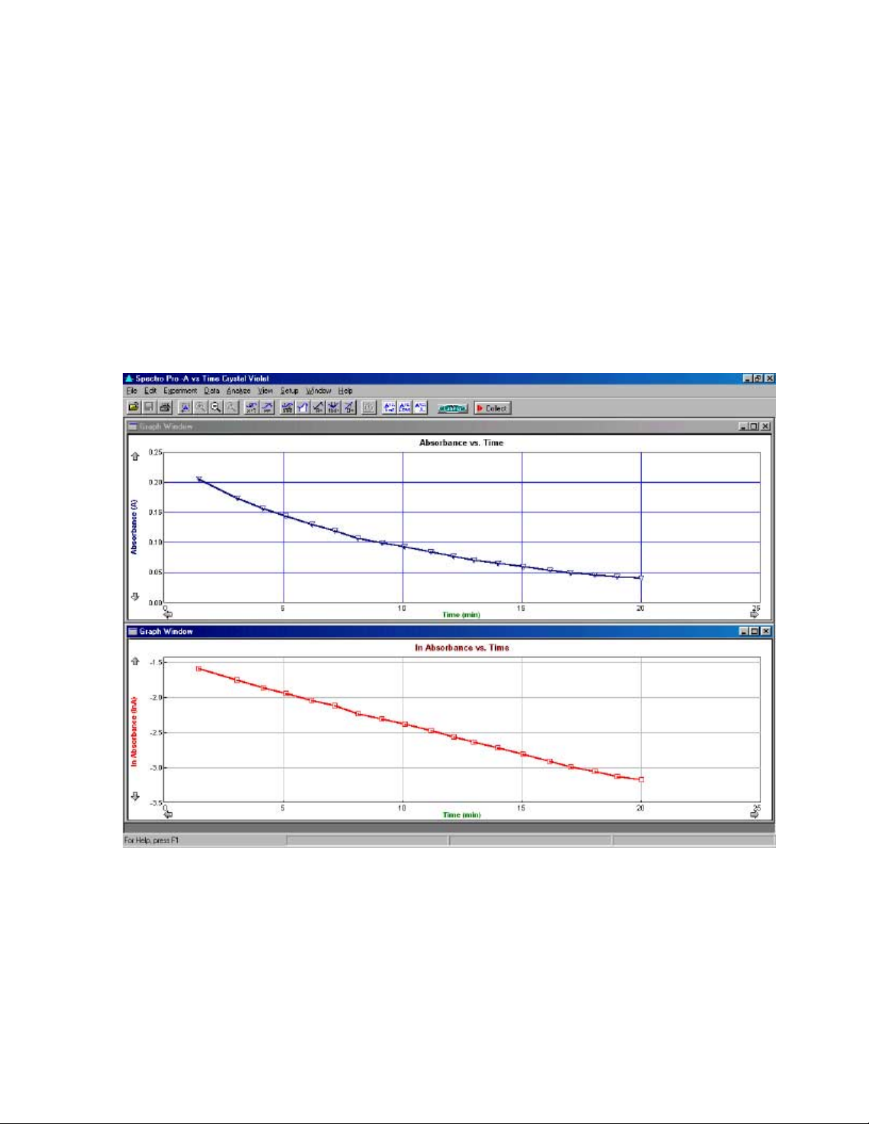
As an example, let us create a calculated column, ln Absorbance, and
then plot a graph of ln Absorbance vs. Time:
First, choose New Column/Formula from the Data menu. You will see
the following dialog box, without the entries you are about to make.
Click on the Options tab to be sure this pane is on top.
24 Spectr o Pro
Page 23

How To
Labels
To give this example column appropriate labels, enter “ln Absorbance”
as the Long Name, “ln Abs” as the Short Name (used in places where
there isn’t room for the whole name), and leave the units blank.
In this dialog box you can als o make other choices for the new column
such as color for graphing. Or, you may not want to show this new
column in the data table. To hide it, click the Hide Column in Table box.
Next, click on the Definition tab to see the rest of the dialog box and to
complete the column creation process.
Spectro Pro 8
Page 24

How To
Equation
The Equation field is where you will build the formula that defines the
new column. Enter the correct formula for the column into the Equation
edit box. To do this select “ln” from the Functions list. Then select
“Absorbance” from the variables list. (To avoid typographical errors,
choose variable and function names from the Variable and Function lists
rather than typing them in.) In the Equation edit box, you should now
see displayed: ln “Absorbance”. Click
vs. Time should also be displayed.
Graph Column On
The newly calculated column can be graphed either on the y- or the xaxis. In this case the default of the y-axis is appropriate. The new
column will replace whatever had been graphed on its column.
Try New Column
When you click on the Try New Column button, the calculation will b e
performed and plotted if some data have already been collected. If you
like what you see, click on OK to return to the main graph window
which will include the calculated plot.
. A graph of ln Absorbance
Enter data manually
Copy data to a spreadsheet
or graphing program
To enter a data column manually, choose New Column Æ Manual from
the Data menu. Enter a label, short label, and units in the fields
provided. Choose a c olor and point protector as desi red.
The data table will contain a new, blank column. Click on a cell to type
in values.
To paste a column of numbers from the clipboard into a Manual Entry
column, click the first cell, then choose Paste from the Edit menu.
You must h ave already collected data from a spectrophotometer to enter
data manually. The maximum number of manually entered points is
limited to the number of points already collected.
To copy all or part of your data in numerical form, select the desired
portion of the data table; you can select it all by choosing Select All from
the Edit menu. Next, choose Copy from the Edit menu to place the data
on the clipboard. Now switch to the destination application.
Once you have the receiving spreadsheet ready to accept the data,
choose Paste from the Edit menu. The data will appear in the
application. You do not have to quit Spectro Pro to switch to another
application.
26 Spectr o Pro
Page 25

Save and Print Data
How To
Save data, calibration and
configuration
Paste data into other
applications
Retrieve an experiment
Print a graph or data table
Print the screen
Set default file locations
You can save your experiment to disk by choosing Save from the File
menu. The experimental configuration, including data, column
definitions and window types will be saved. A stan dard save file dialog
box will appear. Ch oose a location for the file, enter a descriptive file
name, and click on O K.
Saving a complete configuration in this manner is an excellent way to
record an experiment so you can later reproduce or extend the work in
identical conditions. In addition, instructors can save a configuration for
students to use later; students then do not have to perform any
config uration or calibrat ion and can immediately begin to collect data.
Select the data and choose Copy from the Edit menu to place the data on
the clipboard. Paste the d ata into the receiving application, or to a text
editor to create a text format data file.
Choose Open from the File menu, and navigate to the folder containing
the desired file. Click on the file name. Since experiment configuration
is stored in a Spectro Pro file, on loading the file any current
configuration will be overwritten.
To print a graph or data table, make the graph or data tab le the active
window by clicking on it, choose Print Window from the File menu, an d
respond to the resulting dialog box.
To print the entire Spectro Pro screen, choose Print Screen from the File
menu.
The default location of calibration and experiment files can be set in
Spectro Pro preferences. While experiment files may be stored
anywhere, Spectro Pro will first look in the default experiment file
folder. Calibration files, both those saved by users and those supplied
with Spectro Pro, must be within the default calibration folder.
Spectro Pro 8
Page 26

How To
To set default file locations choose Preferences from the File menu. You
will see this dialog box.
Click on the appropriate Browse button to change either the default
calibration or experiment file folder. Choose the desired folder in the
subsequent dialo g, and click OK.
28 Spectr o Pro
Page 27

Teacher’s Guide
Software Installation
Spectr o Pro Reference
Required materials
To use Spectro Pro, you must have the follow ing equipment:
A computer:
•
A PC running Windows 95/98/2000/ME, Windows NT 4.0 with
at least 16MB RAM, and at least a 486 processor. Serial ports
must have a 16550 UART chip. If the computer’s mouse is
connected to a serial port, this means the computer will need
two serial ports. (P lease contact us for further deta ils.) Users of
LabPro with Windows 98/2000/ME may substitute a USB
connection for the serial connection.
or:
•
A Power Macintosh or Power PC runni ng Syst em 7.6.1 or newer
with at least 16MB RAM, 10 MB of hard disk space, and an
unused modem , printer, or USB port.
A spectrophotometer:
Spectro Pro supports The rmo Spectronic and Flinn
spectrophotometers in the following configurations:
•
Spec 20 (Analog signal only) – must be connected to a computer
interface such as
¾ A Vernier LabPro (CH1) using an SPC-BTA cable.
¾ ULI (DIN 1) using an SPC-DIN cable.
¾ A Serial Box Interface (Port 1) using an SPC-DIN cable.
•
Spec 20D or D+ (Digital signal) – can be connected directly to a
computer Serial Port using an SPC-IBM cable for PC or an
SPC-MAC cable for Mac. If a serial port is not available,
connect through an interface as directed above, or use a
KeySpan Serial-to -USB adapter.
•
20 Genesys (Dig ital signal only) – can be connected directly to a
computer Serial Port using a GEN-PC cable for PC or a GENMAC cable for Mac.
•
Flinn Spectrophotometer (Digital sig nal only) – can be
connected directly to a computer Serial Port using an SPC-F LI
cable for PC or SPC-FLM cable for Mac
All interfaces and cables are available from Vernier Software &
Technology. In addition, you may purchase Flinn Spectrophotometers
from Vernier. Contact us at: 13979 S.W. Millikan Way, Beaverton,
Oregon 97005-2886, (503) 277-2299, email: info@vernier.com, web
site: www.vernier.com.
Initial setup
See Appendix C for a discussion of the differences between the
interfaces.
•
If using a Sp ec 20D or D+ (digital signal):
Spectro Pro 8
Page 28

Spectr o Pro Reference
You may connect directly to a computer Serial Port using an SP CIBM cable for PC or an SPC-MAC cable for Mac. If a serial port is
not available, connect through an interface as directed above, or use
a Key Span serial-to-USB adapter. (Note: The Keyspan Adapters
have not been extensively tested with Spectro Pro, nor have other
brands of USB to Serial adapters been examined.)
•
If using a 20 Genesys (digital signal only):
You may connect directly to a computer Serial Port using a GEN-PC
cable for PC or a GEN-MAC cable for Mac.
•
If using a Flinn spectrophotomete r (digital signal only):
You may connect directly to a computer Serial Port using an SP CFL I cable for PC or SPC-FLM cable for Mac.
•
If using a Sp ec 20 or 20+ (analog signal only):
You must connect to a computer interface:
¾ LabPro: Connect to CH1 of a Vernier LabPro with an SPC-BTA
cable.
¾ ULI: Connect to DIN1 of a ULI using an SPC-DIN cable.
¾ Serial Box Interface: Connect to Port 1 of a Serial Box Interface
using an SPC-DIN cable.
¾ Attach the power adapter to the interface and to a source of
115VAC.
¾ Connect the interface to the computer using the supplied cable.
On the Macintosh you can use any serial port, including the
modem and printer ports. On the PC you can use any of the
COM1, 2, 3 or 4 serial ports. LabPro users can also use the USB
port and cable on a USB-equipped PC or Macintosh.
Software installation
Macintosh
Software installation
Windows
Software installation
(network)
To install Spectro Pro on a Power Macintosh, follow these steps:
•
Place the Spectro Pro CD in the CD-ROM drive of your computer.
•
Double-click the icon Install Spectro Pro and follow the instructions
on screen.
To install Spectro Pro on a computer running Windows 95/98/2000/NT
4.0, follow these steps:
•
Place the Spectro Pro CD in the CD-ROM drive of your computer.
•
If you have Autorun enabled, the installation will launch automatically;
otherwise choose Settings Æ Control Panel from the Start menu.
Double click on Add/Remove Programs. Click on the Install b utton in
the resulting dialog box.
•
The Spectro Pro installer will launch, and a series of dialog boxes will
step you through the installation of the Spectro Pro software. You will
be given the opportunity to either accept the default directory or enter a
different directory.
If your computers are served software from a central file server on a
network, you can install Spectro Pro on the server.
Additional suggestions for configuring a network server to work with
Spectro Pro can be found in Appendix B.
30 Spectr o Pro
Page 29

Spectr o Pro Reference
Ideas for using Spectro Pro in the classroom
Experiment files are
important!
Experiment files included
with Spectro
Pro
Experiment files contain information about the particular configuration
of Spectro Pro, including the number of graphs, what is plotted on each
axis, and the data collection rate and mode. In other words, a complete
data collection environment can be saved for later use. Once an
appropriate experiment file is loaded and the interface and/or
spectrophotometer connected, you are ready to collect data.
Many teachers find that they spend less time teaching computing and
more time teaching science if they make use of experiment files. You can
also create your own experiment files for use with custom laboratory
experiments. See the section below on creating your own experiment
files.
Spectro Pro comes with four experiment files, three of which are
configured for taking Absorbance vs. Time, Absorbance vs.
Concentration and Absorbance vs. Wavelength data using a
spectrophotometer. The fourth set includes sample data for five different
experiments.
Protecting experiment files
When experiment files are installed on individual computers, it is
important to keep the files from being unintentionally altered. The openfile dialog box includes a check box marked Open as Read On ly. When
the check box is marked (the default), a file is open ed as read-only. A
read-only file can be used normally, but it cannot be saved using the
Save command. The save button on the toolbar and the Save command
are disabled, and if the user clicks Save As…, the file name field is
blank. The file can be saved under any name, but if the name matches an
existing file an extra confirmation dialog will be presented.
If you intend to make permanent changes to an experiment file, clear the
check box, open the file, and make the desired changes. Save your file.
Spectro Pro 8
Page 30

Spectr o Pro Reference
Creating an experiment file
To create your own experiment files, you will need to set up Spectro Pro
as appropriate for your experiment. You may want to start with an
existing experiment file that is close to the configuration you need.
•
Configure or confirm that Spectro Pro is properly set for the data
collection mode yo u will use.
•
Define any new columns you need.
•
Set up the graphs as desired. Create the number of graphs, the
scaling, and what is plotted for your experim ent.
•
Consider entering an Experiment Note (choose About filename from
the Help menu, where filename is the experiment file name) to give
preliminary instructions that will be displayed when the file is first
opened.
•
Consider adding an explanatory or instructional text window that
will be visible during data collection. (Choose New Window
Text)
•
Test your setup by performing a trial experiment, and make changes
as needed.
•
If you do not want to save your example data with the experiment
setup, clear the data by choosing Clear All Data from the Data
menu.
Æ
Customizing Spectro
Using Spectro
network
Using Spectro
stand-alone computers
Pro
Pro
on a
on
Pro
•
Choose Save from the File menu. Enter a descriptive file name, and
save the file.
To use the file later with studen ts, place a copy of the file in the default
experiment file directory specified in the Spectro Pro preferences.
Certain settings of Spectro Pro, such as the default location of files
which you are unlikely to change every session, can be stored in
preferences. See Preferences under the File menu. Preferences are stored
locally on the computer. Consult Appendix B for detailed network
suggestions.
Using Spectro Pro on a network is similar to using it on a stand -alone
computer. However, the benefits of network access to Spectro Pro
include the need to install only one copy of the software, further
protection of experiment and calibration files from accidental change,
and reduced hard disk requirements on the local computers. For details,
see the discussion in Appendi x B.
During the installation process above, a directory will be placed on your
hard disk which includes Vernier calibration files and experiment files.
Preferences will initially be set to these directories as default.
32 Spectr o Pro
Page 31

Spectr o Pro Reference
Spectro Pro Reference
Keystroke Equivalents
Spectro Pro supports standard keystroke equivalents for common menu
commands. On PC hold down the Control key (it may be labeled Ctrl on
your keyboard) and the appropriate letter key. On Macintosh computers
hold down the Command key while striking the appropriate letter key.
command keystroke
Collect/Stop Enter
New Control/Command N
Save Control/ C ommand S
Open Control/ C ommand O
Print Screen Control/Command P
Striket hrough Rows Control/ Command K
Autoscale Once Control/Command U
Store Latest Run Control/Command L
Replay Control/ Command R
Integrate Control/Command I
Copy Control/ Command C
Cut Control/Command X
Paste Control/Command V
Adjust Data Collection Control/Command D
Adjust Sampling Control/Command M
Examine Control/Command E
Toolbar
The toolbar provides quick access to some common functions . From left
to right, these are Open, Save, and Print Screen. The next group includes
Autoscale Once, Zoom In, Zoom Ou t, and U ndo Zoom. Th e third group
toggles Analyze, Tangent, Statis tics, Int egral, Line Fit, Automatic Curve
Fit and Interpolate. Next, the stopwatch button opens the data collection
dialog box for Absorbance vs. Time experiments.
The icon showing the interface (or spectrophotometer) selects a pulldown menu that allows you to select the serial or USB port to which
your interface (or spectrophotometer) is connected. The Collect button
initiates data collection.
Spectro Pro 8
Page 32

Spectr o Pro Reference
You can quickly see what a tool does by positioning the pointer over the
button for a moment; a tool tip will appear.
Cursor Controls
You can change the graph appearance and behavior through a number of
“hot spots” on the Graph Window and the Table Window. The screen
below shows some of these functions.
Graph Window
Graph title
Tick mark labels
Axis labels
Scroll arrows
Axes
34 Spectr o Pro
These areas of the Graph Window are active to cursor control:
Click on the graph title to obtain a dialog box in which you can modify
or remove the graph title.
You can click on the minimum or maximum axis numeric labels and
type in a new value. The axis of the graph will change accordingly.
When the independent variable is time, the right-most time value will
also determine how long data are collected except when the graph has
been turned into a strip chart.
Clicking an axis label will open a dialog box that allows you to choose
what is plotted on that axis.
You can scroll the viewing region of the graph with the scroll arrows.
The axis limits will change, but the interval displayed by each axis will
remain the same.
To change the scale of one axis at a time, click on the area between the
axis and the axis label. A dialog box will open, allowing you to control
the scaling of that axis.
Page 33

Spectr o Pro Reference
Graph options
Selecting a graph
Table Window
Select All/None
Column properties
Double-click on a graph to change several properties at once. The Graph
Options dialog will appear; allowing you to change scaling, labels, or
plot style. More details can be found under Graph Options in the Spectro
Pro Menus section.
If there is more than one graph window on the screen, most commands
that affect graphs will change only the selected graph window. To select
a graph, click on it. A border will appear around the graph to indicate
that it is selected.
The Table Window also responds to clicks:
Clicking the All/None button will alternately select all data and no data.
Double-clicking the row numbers will open the Table Options dialog.
There you can change the font used and choose which columns will be
displayed.
Column options
Column order
Edit cell contents
Strikethrough Rows
Double clicking the Run Heading (Latest, Run 1, and so forth) will open
a dialog box holding a list of columns. Select a column, click on OK,
and the Column Options dialog for the chosen column will open.
Double-clicking a specific column header will open its Column Options
dialog directly. You can find more details about Column Options under
the Data menu details below.
To rearrange the order of displayed columns, drag the column header to
the desired position.
Only cells in manually entered columns or prompted columns collected
in Events with Entry mode can be edited. Click the cell to be changed.
Type in the new va l ue, and press enter.
To ignore spectrophotometer-collected data (which is not editable),
select the data range in the table and choose Strikethrough Rows from
the Edit menu. Selecting stricken-through rows in the table and choosing
Restore Rows from the Edit menu restores this data.
Spectro Pro 8
Page 34

Spectr o Pro Reference
Spectro Pro Menus
Apple menu
About Spectro Pro…
File menu
(Macintosh only)
Choose this item to display information about Spectro Pro. The version
number and copyr ight notice are displayed.
New…
Open
Close
Save
Save As…
Import Data
Choose New… to open the startup window and data table for the
appropriate experiment setup. All prior data, and configuration
information will be lost.
Choose Open to open a previously stored experiment file or a sample
file. In addition to standard open-file dialog features, there is a check
box which when filled will cause files to be opened as read-only. A readonly file can be used for data collection, but if the user clicks or chooses
Save an error message will be displayed, protecting the original file. A
read-only file can be saved under a new file name using Save As…. The
default is to open files as read-only.
Close closes the current experiment without quitting Spectro Pro.
Save will record the current experiment to disk. If the experiment has
not been saved before, Save is equivalent to Save As. If the experiment
has been prev iously saved, the experiment file is updated.
This will save the current experiment setup including any data in the
data table. Opening this file later will restore Spectro Pro to its current
setup.
Use this feature to import data saved with the Export Data option also
found in the File menu. These data exist in a tab-delimited text format,
and are imported into the Latest data run. Each file has a specific
structure that includes a time stamp, d ata column names, short names,
units, and data. If you make changes to the exported file, be sure to
preserve the original structure. After choosing this option, select the
appropriate file.
36 Spectr o Pro
Page 35

Export Data
Spectr o Pro Reference
This option exports data to a tab-delimited text file. Only raw data
including time and manually entered data from the data run you select
are exported to the file. Calculated columns or curve fit columns are not
saved. A time stamp, column names, short names, and units are saved to
the beginning of the file. After choosing this option, enter the name of
the file you wish to create.
: Do not confuse this option with the
Note
Save or Save As options which save all the details of the current
experiment. Use the Export Data option only if you want to create a file
that can be read by other applications such as spreadsheets or word
processors. You can instead use copy and paste features to trans fer data
to other applications.
Printing Opt i ons
Printing Options calls a dialog box in which you can set text th at will b e
printed with any graph or data table. This helps to identify printouts
coming from a shared printer. If the Date field is checked, the date and
time of printing are included on the page. If the Always Show Page
Setup field is checked, this dialog box will be displayed whenever the
print command is issued. In that case, clicking OK will then display the
Print dialog box where the number of copies is set.
Clicking on the Page Setup button will display the current printer’s
setup dialog. Options such as print quality and paper source can be
chosen here. The same dialog may be accessed with the next menu item,
Page Setup.
Page Setup
Print Window
Print Preview
Print Screen
Page Setup accesses your printer’s Print Setup dialog where you may see
which printer is to be used, change the printer’s properti es, and the paper
size and print orientation.
Choose Print Window to print either a graph or data table window,
whichever window type is active. If the active window is a graph
window with more than one pane, you will be given a choice of printing
one pane or all panes. The available options will d epend on the type of
printer available.
Print Preview will show a reduced-size image of the page as it will be
printed. This is useful to ensure that a given print request won’t take too
many pages.
Print Screen prints the entire Spectro Pro main window with all of the
window types currently displayed as they look on yo ur screen.
Spectro Pro 8
Page 36

Spectr o Pro Reference
Preferences
There are three classes of Spectro Pro settings under user control:
default file locat ions, graph behavior, and hardware.
The default locations of calibration information and experiment files
can be set using the Folder Locations tab.
Spectro Pro will only detect calibration files stored in the default
calibration folder.
In contrast, experiment files may be stored anywhere, but Spectro Pro
will first look in the default location set here.
To set either folder location, click the appropriate Browse button and
navigate to the desired folder, or just type in th e full path to the desired
folder.
Preferences are stored for the use of Spectro Pro and are not saved with
experim ent files.
38 Spectr o Pro
Page 37

Spectr o Pro Reference
The Graph behavior preferences tab allows you to set graphing options.
If Over Range Autoscale is checked, Spectro Pro will automatically
rescale the graph vertically during data acquisition to include any data
point acquired even if it may exceed the existing ran ge settings of the
graph.
Graph behavior preferences allow graph drawing and text to be
emphasized for overhead projection.
The Hardware tab allows you to determine to which in terface Spectro
Pro defaults when no real in terface is attached. This allows experiment
setup without a physical interface attached to the computer. Most Recent
is the last interface to which Spectro Pro connected on this computer.
Quit (Macintosh) or Exit (PC)
Choosing Quit or Exit causes Spectro Pro to prompt you to save any
unsaved data, then exits the program.
Spectro Pro 8
Page 38

Edit menu
Spectr o Pro Reference
Undo
Cut
Copy
Paste
Clear
Select All
The Undo command will reverse the effect of the most recent operation
(if possible). For example, after data collection, the Undo command
becomes Undo Collect. This is valuable if the previous run is needed but
had not been stored.
Cut removes the selected data and places it on the clipboard. Not all data
may be removed. Measurements made by Spectro Pro directly (the raw
data) are locked and cannot be deleted . New column s th at you create are
unlocked and can be edited or cleared.
The locking of raw data columns is an intentional feature of Spectro Pro.
Since the raw data are simply a record of what is measured by the
spectrophotometer, it is inappropriate to change them, much as a
scientist never erases data from a notebook.
When a graph window is the active window, Copy will place a copy of
the graph on the clipboard. When a table window is the active window,
Copy will copy the d ata to the clipboard. You can then paste from the
clipboard into another application.
Paste places a copy of the clipboard contents at the cursor location.
Pasting is possible in the text window and into Manual Entry data
columns.
Clear removes the selected data without putting them on th e clipboard.
Locked data such as original data may not be removed. Only manually
entered data may be cleared.
Select All is used to select the entire data table for subsequent copying.
Strikethrough Rows
Strikethrough Rows disables all selected rows (those points won't be
drawn or used in any way). It display s each selected row in the data table
with a line drawn through it.
Restore Rows
Restore Rows reverses the Strikethrough action for the selected rows.
Experiment menu
40 Spectr o Pro
Page 39

Spectr o Pro Reference
Collect
Replay
Collect begins a data collection run. Clicking the Collect button in the
toolbar or pressing the Enter key has the same effect.
After data are collected, choose this item to get an instant replay of the
data collection. Select the run you wish to replay from the drop-down
menu. You can s et the replay rate to faster than real time, slower, or to
the original rate.
Stop
Live Readouts
Stop causes data collection or replay to cease.
This is a t oggled mode. Choose Live Read outs to turn th e mode on (a
checkmark appears next to the menu item); choose it again to turn off.
When the Live Readouts mode is on, the current sensor readings will be
displayed in any meter window. When Live Readouts is disabled, the
meter window reports the sensor value on the graph nearest the cursor
position. The current sensor readings are always displayed in the status
bar.
Spectro Pro 8
Page 40

Options
Spectr o Pro Reference
Spectro Pro uses a range of points to calculate derivatives, tangent line
slopes, and smoothed data. You can set the number of points used for
these functions. The first setting affects the derivative( ) functions used
in column definitions as well as the drawing of tangent lines. The
second setting affects only the smooth( ) functions used in column
definitions.
In either case, a smaller number of points will make the functions more
responsive to small changes in the data, but larger numbers will reduce
noise.
Calibrate
The Enable Automatic Curve Fit option is checked by default.
Unchecking it will disable the Automatic Curve Fit function from the
Analyze menu and the Toolbar. Users may wish to disable automatic
curve fits to force students to perform manual curve fits instead.
All settings in the Options dialog are stored with an experiment file.
Selecting Calibrate brings up a dialog box that displays calibration
instructions for the particular mode in which data is being collected.
42 Spectr o Pro
Page 41

Data menu
Spectr o Pro Reference
Store Latest Run
Æ
Æ
Æ
Æ
Æ
Æ
Show Run
Hide Run
Rename Run
Delete Run
About Run
Æ
Æ
Æ
Æ
To preserve a run in memory choose Store Latest Run. If you do not
store it, the next time the Collect button is clicked the latest run will be
deleted automatically. Stored runs are numbered sequentially as Run 1,
Run 2, and so forth. You can store as many runs as your computer’s
memory allows.
Show Run is a hierarchical menu, which allows you to select which runs
will be shown on the graphs and data tables. The number of choices
depends on how many runs yo u have store d.
Hide Run is also a hierarchical menu . It allows you to keep a run from
being plotted or shown in the data table. You can choose between the
latest run and a ny stored runs.
Rename Run gives you the option of giving each data collection run a
meaningful name.
Delete Run allows you to remove any stored run from memory, as well
as the latest run.
Choosing a run from the hierarchical menu of About Run shows the time
the data collection began. A text area allows you to enter notes about a
run. This information is only available by again choosing About Run.
Spectro Pro 8
Page 42

Sort Data
Spectr o Pro Reference
Sort Data will arrange rows in
the data table according to
values of the selected column.
This function is useful if data
were gathered in another order,
and now you want to integrate
or plot the data with connecting
lines.
On selecting Sort, you will see
a dialog where you can choose
the column that will determine
the sort order, and whether the
sort is ascending or de scending.
Once you have sorted a data
column, the sort will be
performed on all subsequent runs as the data are collected.
New Column
This command allows you to define a new column of data that will
appear in the data table and optionally on the graph. The new column
may be either a column calculated from other columns us ing a formula,
or it may be manually entered. For both types of new columns a tabbed
dialog box appears. The new column must be named and may be given
units.
44 Spectr o Pro
Page 43

New Column
Æ
Formula
Æ
Spectr o Pro Reference
After setting the new column name and units, formula-based new
columns require a defining formula. The definition tab allows you to
define new columns based on other columns using an equation. To
create a new column based on an equation, enter the desired relationship
in the equation field. The contents of existing columns can be chosen
from the Variables menu, and common mathematical functions can be
chosen from the Function list.
The functions include several appropriate to co lumns of data:
integral
The integral function gives the running sum of the product of point
values and the increment of the independ ent variable, which is usu ally
time. That is, it delivers the numerical integral of the data column.
trigonometric
Tri gonometric functi ons like sine, cosine, and tangent ar e included.
smooth
The smooth function reduces noise in the indicated column. The number
of point s used for a m oving average is controlled in Options found under
the Experiment me nu.
initial
The initial function inserts the value of the first row of data and for all
rows of data. This can be used to create an au tomatic offset s o that a
column of data is relative to its starting value. For example, "Dist" Initial ("Dist")
the starting position instead of absolute
will
generate a column of data where position is relative to
.
sum
The sum function adds the values for all rows up to and including the
current row.
Spectro Pro 8
Page 44

Spectr o Pro Reference
Graph Column On
The calculated column can be graph ed on either axis. Th e d efau lt ch oice
is the y axis. Click the x-axis label to plot the new column on the
horizontal axis.
Try New Column
Clicking the Try New Column button will graph the new column in the
sample graph. You can make changes to the definition, and check out the
changes by clicking this button again. Click OK to keep the new column
and return to the main Spectro Pro screen. Cancel will close the dialog
box and disca rd any e ntries.
New Column
Modify Column
Delete Column
Column Options
Æ
Æ
Manual
Manual columns only require a name. The new column will be created
in the data table. Select a cell by clicking it. Type in your values, ending
each entry with the enter or return key. You can also paste a column of
data after clicking the first cell. Manual columns are limited to the
number of data points already collected using a sensor.
Modify Column allows you to change the definition of a calculated
column. The same dialog box as for New Column above is displayed.
Use Delete Column to remove unneeded columns.
Column Options opens a dialog in which you can change the name of
the column, change the point style used, units , and displayed precision
of data. Use this option to modify existing columns.
Clear All Data
Clear All Data removes all data from the data table. You will be
prompted t o save any unsave d da ta.
46 Spectr o Pro
Page 45

Analyze menu
Examine
Spectr o Pro Reference
Examine is a t oggled mode (a che ckmark ap pe ars n ext to the men u it em
when it is on). When active, the mouse pointer becomes a vertical line
and the value of the data at the indicated time is d isplayed in the graph
legend.
Tangent
Make Annotation
Interpolate
Linear Fit
Automatic Curve Fit
Tangent i s a toggled mode (a chec kmark appears next to th e menu it em
when it is on). Tangent enables the drawing of a short tangent line at th e
cursor location to each data column plotted. The numerical value is
displayed in a floating box. The number of points used to calculate the
slope can be se t in under Prefere nces in the F ile menu.
Make Annotation allows you to create a floating box with any text you
choose. This is useful for placing comments on graphs. To edit an
annotation, double click on the floating box. To remove an annotation,
click the close box on the upper right corner of the floating box.
The interpolate function can only b e used after a function h as been fit to
experimental data using the Automatic Curve Fit…, Manual Curve
Fit…, or Lin ear Fit function described below. After choosing interpolate,
the value of the fitted function is displayed as a function of cursor
position.
Linear fit performs a linear least-squares fit on the selected data. If there
is no selection made the entire data run is used.
The Automatic Curve Fit item gives you a choice of advanced curvefitting options. These curve fits are automatic in the sense that the fit
parameters are determined by Spectro Pro using the least-squares
methods. The dialog box below is opened.
Spectro Pro 8
Page 46

Spectr o Pro Reference
The graph portion of this window gives you a preview of the fit and
allows the selection region to be modified. To perform a curve fit,
choose first the type of fit from the scrolling list at lower left. For the
case of the polynomial fit, enter the degree of the polynomial in the
Degree field. Next, choose the column to be approximated by the fitted
equation. Click on Try Fit to see the result. Modify your choices as
desired. You can modify your data selection by repeating a drag across a
portion of the data and clicking on Try Fit again. Once you like the fit,
Click on OK to place the fit on the main graph window, or Cancel to
discard the fit altogether.
Clicking Create Column will place a new column in the data table
containing the value of the fitted equation at each time.
The Curve Fit Options tab holds a ne w dialog bo x.
The Curve Fit Options tab allows you to determine which fit statistics
are displayed on the graph. The Equation’s Coefficients are the fitted
parameters. The Mean Square Error and its square root, the Root Mean
Square Error, measure how far away on average the fitted function is
from the data. The Root Mean Square Error is in the units of the data on
the y-ax is.
You can also specify the style and color of the line representing the fit.
The Sample Line region provides a preview of the line appearance.
The Displayed Precision field allows you to set the number of displayed
digits in the curve fit floating boxes. Select one of Decimal Places (a
fixed number of places past the decimal point) or Significant Figures
(the number of digits displayed, plus any need to show magnitude).
Enter the desired numerical setting for either mode.
For the linear fit only, the fit and its statistics are determined as follows.
We have N ordered pairs of x
then given by
48 Spectr o Pro
and yi. The best fitting line y = ax + b is
i
Page 47

Spectr o Pro Reference
1
axyxxy
=−
bNxyxy
=−
where
2
()
ii iii
∆
1
()
∆
ii i i
Nx x
∆= −
∑∑∑∑
∑∑∑
2
ii
2
()
∑∑
Measures of the goodness of fit are many. Most common are the scatter
standard deviation,
uncertainties of the parameters a and b,
deviation measures how far away, on average, the data points
the fitted line, measured along a vertical line.
, the linear correlation coefficient r, and the
σ
s
σ
and
a
. The scatter stand ard
σ
b
1
is also called the root
σ
s
y
i
fall from
mean square error, and is defined as
σ
sii
1
=
N
yabx
−−
()
∑
2
−
2
.
We us e N - 2 weighting since two parameters have been determined in
the curve fit.
The remaining quantities are defined as
2
σ
s
2
=
σ
a
N
=
σ
b
r
=
Nx x Ny y
x
∑
i
∆
2
σ
s
∆
Nxy x y
2
−
() ()
∑∑∑∑
ii ii
−
ii i i
12
2
∑∑∑
2
−
12//
2
The first two quantities are interpreted as the variance of the fitted
parameters, and so can be used as 6 7% confid ence level uncertain ties of
the slope and intercept.
The correlation coefficient, r, is commonly calculated by scientific
calculators, but is a difficult quantity to interpret. The correlation
coefficient is intended to measure the degree of correlation between the
x
and y values. It is not directly a measure of goodness of fit. For no
correlation at all (random values), r is near zero. For perfect correlation
is ±1. From r one can determine a probability that the x and y values are
correlated. In the natural sciences, however, there is usually the
assumption that the two
are
correlated, and so the r value is not very
useful. Far more useful to a student or scientist is the uncertainty of the
slope and intercept. These uncertainties answer the question “How well
did the data determine a slope (or intercept)?”.
r
Manual Curve Fit
No provision has been given to weighted fits, since in computeracquired data all data points are generally equally reliable.
More information on curve fitting and the interpretation of the fitted
parameters can be found in
Physical Science,
nd
2
Data Reduction and Error Analysis for the
edition, Philip R. Bevington and D. Keith
Robinson, McGraw-Hill, Inc., 1992.
The automatic curv e fit function can be disabled in the Options, found in
the Exper iments menu.
Spectro
Pro
will superimpose a function (sometimes called a model)
over your data using the Manual Curve Fit option. In contrast to the
1
The least squares fitting method
are negligible compared to the uncertainties of y.
assumes
that the uncertainties in the x value s
Spectro Pro 8
Page 48

Spectr o Pro Reference
automatic curve fit discussed above, where the parameters in the fit
equations are determined automatically using a least-squares technique,
the Manual Curve Fit allows you to adjust the parameters by hand.
A manual fit is often appropriate for instructional purposes. By adjusting
parameters manually, students will learn how each affects the fit. A
manual fit will also allow you to adjust a curve to fit a data series in the
way you want, possibly ignoring cer tain stray points within the series.
To perform a manual fit, click once on a graph to make it active.
Optionally, select a region of the graph using the mouse. This selection
region is used only for calculating the mean square error of the fitted
function with respect to the data. If you do not plan on using the mean
square error value, then it is not necessary to select a region. Then, select
Manual Curve Fit from the Analyze menu. A new dialog box will open.
First, you must select or enter an equation. The faster method is to select
an equation from the General Equation menu. In the screen shown
above, the proportional relationship has been selected. You can also
enter your own relationship in the Equation field. The equation must
contain between one and five adjustable parameters (single upper- or
lower-case letters) and the horizontal axis variable is entered as x.
The values of each parameter may be adjusted in the P arameters fields.
You can either type in a new value directly, or you may u se the up and
down arrows to increase or decrease the values usin g the mouse. C lick,
or click and hold, on the desired arrow.
The ∆ button near each parameter allows you to set the adjustment
increment applied when the arrows are used. C licking on the ∆ button
selects the Auto Delta box. If the Auto Delta box is checked (default is
unchecked) then the increment will be made smaller when the parameter
reaches a magnitude similar to the increment.
Using the manual fit can be very helpful in understanding fitted
functions, but it can also be frustrating. A random or poorly chosen set
of parameter values may result in a function that does not cross the
graphed region at all. Blind adjustment of the parameters will not often
50 Spectr o Pro
Page 49

Spectr o Pro Reference
move the function into view. On ce a part of the function is in view, it is
usually easy to adjust the parameters to get a good fit.
If your graph starts at x = 0, one way to get the function in to view at the
start is to adjust the y-intercept value to match that of your data. Then
you will see at least a portion of the function, allowing you to adjust
other parameters as needed.
Clicking Create Column will place a new column in the data table
containing the value of the fitted equation at each x-axis value.
The Perform Fit On menu allows you to select the column used for
calculating the Mean Square Error value. The Mean Square Error
measures how far away the function is, on average, from the data.
Automatic curve fits seek to minimize this value.
Integral
Statistics
View menu
Integral performs a numerical integration on the selected data.
First drag across the desired region of your data to select. Then
choose Integral (or click on the Integral button on the toolbar). You will
have the opportunity to specify which data set you wan t to integrate. The
numerical result is shown on the graph, and the corresponding area
shaded.
The Statistics item displays a dialog showing statistical measures
of the selected data: maximum, minimum, mean, standard
deviation, and the number of points used. You may optionally select a
region of the data first. The entire data set is used when no selection is
made. After you select Statistics (or click on the Statistics b utton on th e
toolbar) you will have the opportunity to specify for which data set you
want statistics calculated. The statistics are presented in a floating box
on the graph screen.
The standard de viation is found using N-1 weighting, or
σ
1
=
N
()
∑
1
−
2
xx
−
i
.
The first item in the View menu changes depending on the active
window. For example, to see Data Table Options, click once on a data
table before pulling down the View menu. Options settings for Text, and
Meter windows are also available.
Spectro Pro 8
Page 50

Spectr o Pro Reference
Graph Options
Choosing this item is equivalent to double clicking the graph. The Graph
Features tab of the dialog box is shown first:
Point Protector Every … Points
If this item is selected, a marker will encircle one of every N points.
Marker color and shape can be chosen by Choosing Column Options
from the Data menu.
Legend
Selecting Legend causes a legend to appear on the graph. The Legend
identifies the plotted columns by color and line style. A Legend appears
automatically when in Examine mode.
Connecting Line
Enabling Connecting Line draws a straight line from one data point to
the next.
Bar Graph
If this option is selected Spectro Pro will draw vertical bars from the
horizontal axis to each data point. The bar width in pixels can be set in
the width fi eld.
3D
If this option is selected, Spectro Pro will draw the vertical bars of a bar
graph with shadows, giving an illusion of depth.
Grid
A gridline for every tick mark can be displayed if desired. Th e color and
weight of the lines are controlled using the two pop-up menus at the
bottom of the dialog box.
52 Spectr o Pro
Page 51

Spectr o Pro Reference
Graph Title
A graph title can be displayed if desired. The text of the graph title can
be entered in the Graph Title field.
The Gra ph Options dialog also has an Axis Options t ab:
Data Table Options
Here you can control what is plotted on the two axes as well as the
scaling used. The settings here are duplicated in the axis scale and
selection dialogs obtained by double-clicking an axis or axis label. The
columns shown will depend on your specific configuration of Spectro
Pro. Scaling choices will also be used in subsequently collected data.
Data Table Options lets you control the font, size, and presentation of
data columns through two tabbed dialog boxes. The first sets the font,
weight and size of the numerals:
Spectro Pro 8
Page 52

Spectr o Pro Reference
Choosing Black and White in Table will d isable the use of color coding
of the columns, which may make reading values somewhat easier .
The Table Layout tab controls what columns are sh own in th e tab le. You
may want to hide some columns for clarity. The first option shows all
data. The second allows you to show just one selected run, and the third
lets you display one selected column across all runs. You can also hide
individual columns in the Column Options dialog box.
Meter Window Options
Meter Layout
The data columns displayed in the meter window can be set by the u ser
in this dialog box.
In addition you can control the layout and font size of meter window
readouts.
The three grid layout options determine whether the meters are laid out
to fill the available space with the largest possible meters (Automatic), to
arrange data from each run vertically (By Column) or horizontally (By
Run).
The type size used in meters can either be set b y the user or determined
automatically.
54 Spectr o Pro
Page 53

Graph Layout
Spectr o Pro Reference
Graph Layout allows you to control the way multiple graph panes are
shown in the g raph window. Choose the desired option and click o n O K.
There are two ways to display multiple graphs in Spectro Pro; one is to
use two or more graph windows, and another is to use the Graph Layout
command to display two or more graph panes within a single window.
Graphs in separate windows are independent of one another, although
both depend on the same data table. Graph panes in a single window
share certain adjustmen ts for ease of viewing. These shared parameters
are:
Zoom In
•
Changing the x-axis limits in one pane will automatically change the
limits in other panes.
•
Scrolling the x-axis plotting range using the scroll arrows will scroll
all panes.
•
Zooming into a selected region will zoom the horizontal axis of all
panes in the same manner.
•
Turning on the Examine tool shows the data points for all panes.
These connected adjustments will keep the horizontal axes synchronized
to allow easy comparison of each series. If you want independent
adjustment of the horiz ontal axes, use separat e graph windo ws.
To zoom in on a portion of a graph, first draw a rectangle on the graph
screen by dragging the mouse across the desired area as you see here.
Spectro Pro 8
Page 54

Spectr o Pro Reference
Then choos e Zoom In from the View menu, or c lick on t he Zoom
In button on the toolbar. The graph will rescale, expanding the
selected region to fill the plotting area. If the Zoom In command is used
on one of several graph panes in a single graph window, the horizontal
axis will be changed in all graph panes.
Undo Zoom
Zoom Out
Autoscale Once
Set Axes to Autoscale
Choosing Undo Zoom will reverse the last zoom action
performed, whether by the above Zoom In command or the
following Zoom Out command. You can undo multiple zooms with
multiple Undo Zooms.
The Zoom Out command will double the range of both the x- and
y-axes.
Autoscale Once will change the scales so that the plotted curves
fill the graph area. The scaling only takes place for the current
range of data plotted. You can also click on the Autoscale Once button
on the toolbar.
Set Axes to Autoscale makes the automatic scaling of the currently
active graph permanent so that the graph scales itself au tomatically for
the current data and each subsequent range of data that is plotted . Both x
and y axes may be changed. The y axis will not necessarily include the
origin, so you may want to perform a more limited autoscale by clicking
the y axis and choosing Autoscale from Zero in the ensuing dialog.
56 Spectr o Pro
Page 55

Setup menu
Spectr o Pro Reference
Selecting Setup Absorbance vs. Time will bring up the following dialog
box:
Spectrophotometer\Interface
Using the pull-down menus, you can enter Experiment Length (in
seconds, minutes, or hours) and Sampling Rate. A maximum of 30,000
points can be collected.
You can also access the Setup Absorbance vs. Time Experiment dialog
box by using the toolbar.
Digital spectrophotometers may connect directly to a computer running
Spectro Pro via a special cable (see Appendix C). Analog
spectrophotometers must communicate with Spectro Pro vi a one of the
following interfaces: a Vernier LabPro, a ULI, o r a Serial Box Interface.
The Interface dialog box allows you to force Spectro Pro to search for a
compatible interface. The current communications ch annel is shown in
the drop-down menu. If the most recently used interface is not detected,
“Select port to scan” appears as the Interface. To choose a channel,
select it from the list. That port will be scanned for an interface.
Successful communication with an interface is shown by the identifying
information; here, a LabPro is connected to COM1. Click on OK to
confirm the search and close the dialog. The icon associated with the
interface will appear on the toolbar. The next time Spectro Pro is started
the selected port will be used. If no interface is detected on th e selected
port, the OK button will change to Scan. Use this button to re-scan the
currently selected port, or click Cancel to leave the dialog without
searching for an interface.
Spectro Pro 8
Page 56

Spectr o Pro Reference
It is only necessary to use this dialog if you are using an analog
spectrophotometer and Spectro Pro is started without the interface
connected or powered, or if communication with the interface is lost.
The interface to which Spectro Pro defaults, with no real interface
attached, is controllable. For example, to setup an experiment for a given
interface without being connected to that interface, go to Preferences on
the File menu, choose the Hardware tab, and select the Default Interface.
The Setup Interface dialog can also be accessed by clicking on the
LabPro icon on the toolbar.
Window menu
New Tall Window
New Wide Window
Æ
Æ
Æ
Æ
New Tall Window creates a new window. The current window is halved
in width and the new window is created beside the resized active
window. A hierarchical menu, New Window has the following choices:
•
Graph: Choose Graph to create a data plot.
•
Table: Choose Table to create a new data table.
•
T ext: T ext opens a text edit window for comments.
•
Meter: Meter creates a window with digital readouts of data.
•
ActiveX: Choose ActiveX to create an ActiveX window from
V isualizer, Excel, Netscape, or movie file.
New Wide Window creates a new window. The current window is
halved in height and the n ew wind ow is created below the resized active
window. New Wide Menu has the same hierarch ical ch oices as the New
Tall Window comma nd above.
58 Spectr o Pro
Page 57

Replace
Window
Æ
Æ
Spectr o Pro Reference
Replace Window also shares the hierarchical choice of the above
commands, but instead of generating an additional window, it replaces
the current window with the selected type of window.
Autotile
Toolbar
3 Graph Window
Help menu
Contents
Index
About Spectro Pro
(Windows only)
About (Untitled)
Autotile is a toggled setting. When checked it forces a tiled layout of
windows whenever a window edge is moved.
Toolbar is a toggled setting. When checked the toolbar is visible on
screen. Uncheck it to hide the toolbar.
The title of each open window is listed at the bottom of the Window
menu. Select the title of the window you want on top.
Help Contents displays the table of contents for on-line help.
Index displays the on-line help index.
About Spectro Pro shows the version num ber and copyright information.
The menu name will change to match the current experiment file.
Choosing this item will open a text entry region for storing notes about
the experiment file. When an experiment file with notes entered here is
opened the notes will be displayed.
About LabPro
If you have a LabPro connected, About LabPro will display the version
number of the LabPro firmware.
Spectro Pro 8
Page 58

Problem Cause Solution
Spectro Pro cannot find the
Interface
Appendix A
Appendix A
Troubleshooting Guide
Spectrophotometer or interface
not correctly connected to
computer
Two or more copies of Spectro
Pro running, or a copy of Logger
Pro is running.
Bad spectrophtometer or
interface cable
Wrong serial port being used Make sure you are using the correct
Spectrophotometer or computer
interface not receiving power
(green light off) or not turned on.
Battery- powered LabPro or
Serial Box has dead batteries
Connect interface to the modem or
printer po rt (Macint osh) or COM1,
COM2, COM3 or CO M4 (PC) using
supplied cable. On a Macintosh or
PC you may use a USB cable and
port for LabPro.
For Genesys 20 and Flinn
Spectrophotometers, be sure the
correct end of the cable is attached to
the spectrophotometer.
Exit all but the first copy of Spectro
Pro.
Replace cable
serial port. For example, don’t
confuse COM1 and COM2 (PC) or
the Printer and Modem ports (Mac).
Make sure the power adapter is
plugged into a wall socket and
connected to the interface.
Turn on power switch (ULI only).
Serial Box: Make sure the green
LED comes on when y o u start up
Spectro Pro.
LabPro: Remove and replace a
battery. You should hear tones and a
flashing of all 3 LED’s.
Whenever possible, use AC power.
Modem port of M acintosh not
available
Spectro Pro 61
If y ou are using a Macintosh with an
internal modem, make sure that the
control panels are set for external
modem.
If y ou are using a Macintosh
PowerBook with a single
modem/printer po rt and are no t
using Ethernet port, AppleTalk must
be turned off to make port available.
Page 59

Appendix A
Problem Cause Solution
Spectro Pro cannot find the
interface.
Computer’s serial port is set up
for internal modem use. (This is
a potential problem for any
computer with an internal
modem.)
Serial port of PC disable d If you are using a laptop PC, make
Modem o r serial port in use by
another program
Reconfigure the serial port for use
with an external modem.
sure the seri al port is not disabled by
a power-saving mode.
Quit any other progra m that could be
using the port, such as a Palm Pilot
or digital camera.
62 Spectr o Pro
Page 60

Problem Cause Solution
The mouse locks up as Spectro
Pro starts up
Cannot save a previously
opened experiment file
Spectro Pro readings do not
match those on
spectrophotometer screen.
No data appearing in g raph Graph range defined too small
Spectro Pro and a serial mouse
conflict (PC)
File has been opened in readonly mode (default).
“Ground Loop.” Computer and
spectrophotometer are using
electricity supplied by two
different circuits.
for data to appear
Appendix A
Hold down the Ctrl key during start
up. The program will not
automatically search for the
interface. Click on the correct COM
port for the ULI.
Clear read-only check-box when first
opening file, or save the altered file
under a new name.
Make sure the computer and the
spectrophotometer are drawing
current from the same circuit.
Select Autoscale Once or double-
click on the graph and select a larger
range of values for the axes.
Spectro Pro 63
Page 61

Appendix B
Appendix B
General principles
Spectro
preferences
Pro
Using Spectro
If your computers are served software from a central file server on a
network, you can install Spectro Pro on the server. Create a folder on the
server to hold Spectro Pro (you will need sufficient privileges2 to do
this). Run the Spectro Pro Installer from the CD, and specify the file
server folder when the installer asks for the d esired location for Spectro
Pro. Set the student access rights to the Spectro Pro folder to read -only
and shareable. Then students can see and run Spectro Pro, but cannot
change it. If stu dents will be setting up sensors themselves or accessing
the Sensor Properties dialog by choosing Sensors… from the Setup
menu or clicking on the interface icon on the toolbar, additional write
access to the calibration files folder is needed.
Spectro Pro will read preferences saved locally on the computer.
Preferences indicate the location of calibration files and the default
location of experiment files. If you want students to use a standard set of
calibration and experiment files, the files should be stored on the server
in a location to which students have the same access privileges as the
Spectro Pro program itself. The preferences must then be set to indicate
the location of these files on your server. Wh en you set the preferences,
you must have write access to make changes to the experiment, or
calibration files.
Two good choic es for t he l ocation of exp erimen t fil es are 1) A pr otecte d
directory on the file server where the students cannot make chan ges; or
2) A local directory where students can store their own files. In the first
case students must b e directed to save files to another directory; in the
latter, experiment files must be placed on each computer and could be
changed inadvertently. To avoid accidental changes, set file attributes to
Read-only (Windows, right-click on file to see dialog) or to Locked
(Macintosh, select file, choose Get Info to see dialog). This way you can
have a reference set of experiment files while students can still save their
own files.
on a Network
Pro
Macintosh
Similarly, calibration files can be stored either centrally on the server or
on individual machines. If your students will use a common set of
calibration files, then choose the former. For the less common case of
individually calibrated sensors (custom calibration done for a specific
sensor/interface/computer combination), then the calibration files must
be stored locally since they will be different for each computer. Lock or
set to read-only those files you do not want changed.
To use the network copy of Spectro Pro, log in to the file server so the
server’s icon is on the Macintosh desktop. Locate the Spectro Pro icon,
and double-click to start. For simplicity, create an alias for Spectro Pro
on the local hard disks. Then, wh en the alias is double-clicked, th e user
will be prompted to log in, the file server disk will be mounted and
Spectro Pro will start.
2
File servers provide some security by only allowing certain users to perform
functions like saving, modifying, or deleting files in certain directories.
Typically only administrative accounts are allowed t o make changes anywhere
on the server—one speaks of having the privilege or right to make these
changes.
Spectro Pro 65
Page 62

Appendix B
Windows
Student use of Spectro
on a network
Pro
To use the network copy of Spectro Pro, log in to the file server and
navigate to the Spectro Pro icon. Double-click on it to start. As a
shortcut in Windows, you may want to drag the Spectro Pro icon to the
Start menu to place Spectro Pro in the Start menu list.
For your students to use Spectro Pro on a network, th ey first must have
adequate access rights. In most situations, stu dent access should allow
Spectro Pro to be seen and executed, but not changed in any way. Your
network administrator should be able to assist in this setting.
If your students need to change sensor settings or calibrations, they also
need to be able to write files to the Calibration folder. This means they
need rights to create and change files in just the Calibration folder. You
may find the location of this folder by choosing Preferences… from the
Edit menu. Again, your network administrator should be able to assist in
this setting.
66 Spectr o Pro
Page 63

Appendix C
Appendix B
Interfaces and Cables for Use with Spectro
Which Interface?
Interface Cost Spectrophotometers Cables
LabPro $220
Serial Box
Interface
Which Cable?
If you have an analog signal spectrophotometer or are u sing the analog
feature of a Spec 20D or Spec 20D+, you can use LabPro, the Universal
Lab Interface (ULI) or the Serial Box Interface with Spectro Pro. The
Serial Box is a low cost interface lacking digital and high-speed inputs,
while the Vernier LabPro and the ULI offer high speed and digital
inputs. The table below will give you the details so you can determine
which equipment you require for your experiments.
$50 for
Spectro Pro
software
$99
$50 for
Spectro Pro
software
Depending upon which spectrophotometer you own, and whether or not
that spectrophotometer is digital or analog, you may require a special
cable to attach your instrument to your computer. These requirements are
listed in the chart below.
Spec 20, Spec 20D,
Spec 20D+
Spec 20, Spec 20D,
Spec 20D+
Pro
SPC-BTA ($25.00)
SPC-DI N ($25.00)
Spectrophotometer Interface
(if applicable)
Spec 20 or 20+ Vernier Lab Pro
ULI
Serial Box Interface
Spec 20D or 20D+* none (direct connect)
none (direct connect)
20 Genesys (requires
firmware version 2.10
to run Spec tro Pro)
Flinn
Spectrophotometer
*If a serial port is not available, a Keyspan USB Serial Adapter may be used (For PCs, Keyspan
High Speed USB Adapter, Part #USA-19W; for MACs, Keyspan USB Twin Serial Adapter, Part
#USA-28x), or yo u may connect through an interface as directed for Spec 20 or 20+, above.
Contact Keys pan directly at (510) 222-0131 or view their Web site ( www.keyspan.com).
none (direct connect) PC
none (direct connect) PC
Computer Type Cable
(available from Vernier)
PC or MAC
PC or MAC
PC or MAC
PC
MAC
MAC
MAC
SPC-BTA
SPC-DIN
SPC-DIN
SPC-IBM
SPC-MAC
GEN-PC
GEN-MAC
SPC-FLI
SPC-FLM
Spectro Pro 67
Page 64

Appendix D
Vernier Sensors
Vernier offers a complete line of sensors t ha t support science education in the lab.
Appendix D
Sensors supported by all
interfaces
Additional sensors for the
ULI and LabPro
Sensor for LabPro only
Experiment and calibration
files
These sen sors can b e used w ith Logger Pro and a LabPro, a Serial Box
Interface or a ULI.
•
25-g Accelerometer
•
Barometer
•
Biology Gas Pressure Sensor
Gas Sensor
•
CO
2
•
Colorimeter
•
Conductivity Probe
•
Direct-Connect Temperature Probe
•
Dissolved Oxygen Probe
•
Dual-Range Force Sensor
•
EKG Sensor
•
Exercise Heart Rate Monitor
•
Extra Long Temperature Probe
•
Flow Rate Sensor
•
Gas Pressure Senso r
•
Heart Rate Monitor
•
Instrumentation Amplifier
•
Ion-Selective Electrodes (Ammonium, Calcium, Chloride, Nitrate)
•
Light Sensor
•
Low- g Accelerometer
•
Magnetic Field Sensor
Gas Sensor
•
O
2
•
pH System
•
Pressure Sensor
•
Relative Humidity Sensor
•
Respiration Monitor Belt
•
Student Force Sensor
•
Thermocouple
•
Turbidity Sensor
•
Voltage Probe
•
3-Axis Accelerometer
•
Microphone
•
Motion Detector
•
Photogate
•
Rotary Mo tion Sensor
•
Sound Level Me ter
•
Student Radiat i on Monitor
•
Stainless Steel Temperature Probe
Experiment files for all supported sensors are supplied with the Logger
Pro package. These experiment files will automatically load Vernier
calibration files for use with these sensors, although other calibration
files may be chosen.
Spectro Pro 69
Page 65

Appendix D
After loading a sensor’s experiment file, Logger Pro will display
appropriate units for that sensor .
Sensor Price List
Sensor LabPro
Price/Order Code
3-Axis Accelerometer $199 (3D-BTA) $199 (3D-DIN)
25-g Accelerometer $91 (ACC-BTA) $89 (ACC-DIN)
Barometer $58 (BAR-BTA) $56 (BAR-DIN)
Biology Gas Pressure Sensor Use GPS-BTA $68 (BGP-DIN)
CO2 Gas Sensor $261 (CO2-BTA) $259 (CO2-DIN)
Colorimeter $99 (COL-BTA) $99 (COL-DIN)
Conductivity Probe $89 (CON-BTA) $79 (CON-DIN)
Current & Voltage Probes $86 (CV-BTA) $84 (CV-DIN)
Direct-Connect Temperature
Probe
Dissolved Oxygen Probe $191 (DO-BTA) $189 (DO-DIN)
Dual-Range Force Sensor $99 (DFS-BTA) $98 (DFS-DIN)
EKG Sensor $142 (EKG-BTA) $140 (EKG-DIN)
Exercise Heart Rate Monitor $91 (EHR-BTA) $89 (EHR-DIN)
Extra Long Temperature Probe $70 (TPL-BTA) $68 (TPL-DIN)
Flow Rate Sensor $129 (FLO-BTA) $128 (FLO-DIN)
Gas Pressure Sensor $71 (GPS-BTA) $70 (GPS-DIN)
Ammonium Ion-Selective
Electrode
Calcium Ion-Selective
Electrode
Chloride Ion-Selective
Electrode
Nitrate Ion-Selective Electrode $165 (NO3-BTA) $163 (NO3-DIN)
Instrumentation Amplifier $51 (INA-BTA) $49 (INA-DIN)
Light Sensor $45 (LS-BTA) $39 (LS-DIN)
Low-g Accelerometer $90 (BAR-BTA) $88 (LGA-DIN)
Magnetic Field Sensor $54 (MG-BTA) $44 (MG-DIN)
Microphone $35 (MCA-BTA) $30 (MCA-ULI)
Motion Detector $64 (MD-BTA) $65 (MD-ULI)
O2 Gas Sensor $186 (O2-BTA) $184 (O2-DIN)
pH Sensor $74 (PH-BTA) $72 (PH-DIN)
Pressure Sensor Use GPS-BTA $69 (PS-DIN)
Radiation Monitor $205 (RM-BTD) $199 (RM-DG)
Relative Humidity Sensor $67 (RH-BTA) $65 (RH-DIN)
Use TMP-BTA $28 (DCT-DIN)
$165 (NH4-BTA) $163 (NH4-DIN)
$165 (CA-BTA) $163 (CA-DIN)
$165 (CL-BTA) $163 (CL-DIN)
SBI or ULI
Price/Order Code
70 Spectr o Pro
Page 66

Appendix D
Respiration Monitor Belt
(Requires GPS-BTA or
BPG-BTA)
Rotary Motion Sensor $187 (RMS-BTD) $185 (RMS-ULI)
Sound Level Meter $209 (SLM-DTA) $207 (SLM-DIN)
Stainless Steel Temperature
Probe
Student Force Sensor $99 (SFS-BTA) $99 (SFS-DIN)
Student Radiation Monitor $145 (SRM-BTA) $138 (SRM-DG)
Turbidity Sensor $99 (TRB-BTA) $105 (TRB-DIN)
Thermocouple $37 (TCA-BTA) $35 (TCA-DIN)
Vernier Photogate $41 (VPG-BTD) $39 (VPG-DG)
Voltage Probe $9 (VP-BTD) $7 (VP-DIN)
Water Depth Sampler $57 (WDS) $57 (WDS)
$58 (RMB) $58 (RMB)
$29 (TMP-BTA) Use DCT-DIN
Spectro Pro 71
Page 67

Index
72 Spectr o Pro
Page 68

A
About Run · 43
Analysis functions · 20
Analyze menu · 20, 47
Annotation · 47
Automatic Curve Fit · 47
Autoscale Once · 15, 56
Axis labels · 34
B
Bar graph · 52
C
Index
Index
Cables · 65
Calibrate · 42
Calibration files, default location · 38
Change graph appearance · 15
Clear · 40
Clear All Data · 46
Close · 36
Collect · 41
Collection rate · 18
Collision timing · 35
Column Options · 46
Connecting line (graphs) · 52
Copy · 26, 40
Creating an experiment file · 32
Cursor controls · 34
Curve fitting · 47
Cut · 40
D
Data me nu · 43
Data table functions · 23
Data Table Options · 53
Default Interface · 58
Delete Column · 46
Delete Run · 43
Digital readout · See Meter window
Spectro Pro 73
Page 69

Index
E
Edit cell contents · 35
Edit menu · 40
Enter data manually · 26
Examine · 47
Experiment files · 31
Experiment files, default location · 63
Experiment length · 18
Experiment menu · 41
Export Data · 37
F
File menu · 36
Fit other functi ons · 20
G
Graph Layout · 55
Graph Options · 52
Graph title · 53
Grid · 52
H
Help menu · 59
Help Topics · 59
Hide Run · 43
How To … · 15
I
Import Data · 36
Installation · 30
Integral · 51
Interface · 65
Interpolate · 21, 47
K
Keystroke Equivalents · 33
L
Legend · 52
Linear Fit · 47
Linear regression · 20
Live readouts · 41
74 Spectr o Pro
Page 70

M
Manual Curve Fit · 21, 49
Manual data entry · 26
Manual fit · 21
Menus · 36
Meter layout · 54
Meter window · 19
Meter window options · 54
Model (Manual Curve Fit) · 21, 49
Modeling · See Manual Fit
Modify Column · 46
N
Network use · 32, 63
New · 36
New Column · 44, 45, 46
New Wide Window · 58
New Window Tall · 58
Index
O
Open · 36
Over Range Autoscale · 39
P
Page Setup · 37
Paste · 27, 40
Point protector · 52
Preferences · 38, 63
Print Preview · 27, 37
Print Screen · 27, 37
Print Window · 27, 37
Printing · 27
Printing Options · 37
Protecting experiment files · 31
Q
Quick Start · 11
R
Replace Window · 59
Replay · 41
Rescale · See Autoscale Once
Restore Rows · 40
Spectro Pro 75
Page 71

Index
Retrieve data · 27
S
Sampling speed · 18
Save As… · 36
Save data · 27
Scroll · 16
Scroll arrows · 34
Select All · 35, 40
Sensors · 67
Set Axes to Autoscale · 56
Set Up menu · 57
Show Run Æ · 43
Smoothing · 42
Software installation · 29
Sort Data · 18, 44
Spectrophotometer/Interface · 57
Spreadsheet, copying data to · 26
Statistics · 51
Stop · 41
Store Latest Run · 43
Strikethrough Rows · 36, 40
T
Table layout · 54
Table options · 23
Tangent · 47
Teacher’s Guide · 29
Text window · 19
Tick mark labels · 34
T oolbar · 33, 59
Troubleshooting · 61
U
Undo · 40
Undo Zoom · 56
Units · 16
USB · 12
V
View menu · 19, 51
W
Window menu · 58
76 Spectr o Pro
Page 72

Window types · 19
Windows · 19
Z
Zoom · 15
Zoom In · 56
Zoom Out · 56
Index
Spectro Pro 77
 Loading...